patent · US5510201
Method of operating a fuel cell wherein hydrogen is generated by providing iron in situ
23 April 1996
Page 1 — bibliographic record
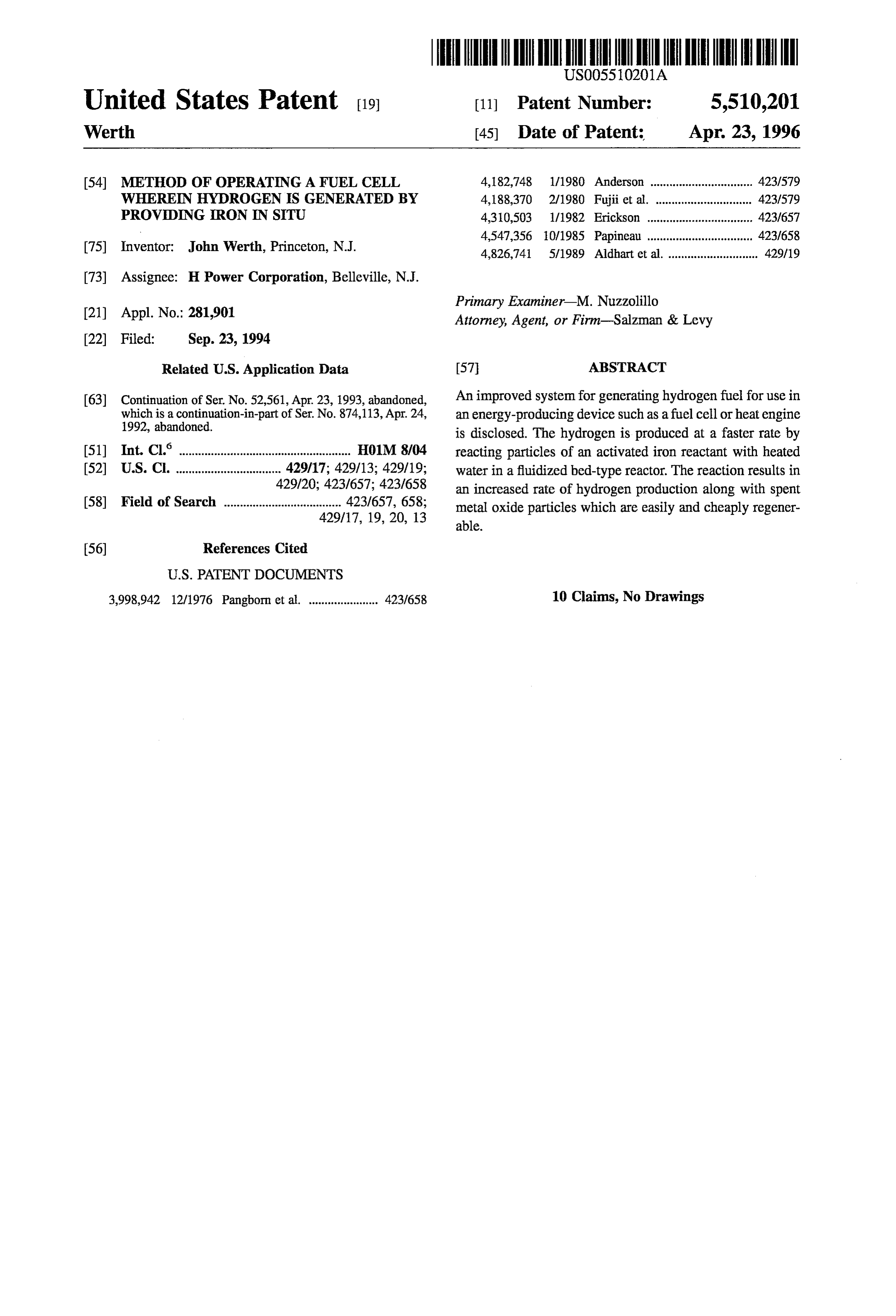
United States Patent (19) 11 Patent Number: 5,510,201 Werth 45) Date of Patent: Apr. 23, 1996 54 METHOD OF OPERATING A FUEL CELL 4,182,748 1/1980 Anderson ................................ 423.1579 WHEREN HYDROGEN S GENERATED BY 4,188,370 2/1980 Fujii et al. ...... ... 42.3/579 PROVIDING RON IN STU 4,30,503 1/1982 Erickson ..... ... 423f657 4,547,356 10/1985 Papineau ......... ... 423/658 75) Inventor: John Werth, Princeton, N.J. 4,826,741 5/1989 Aldhart et al. ............................ 429/19 (73) Assignee: H Power Corporation, Belleville, N.J.
Primary Examiner M. Nuzzolillo (21) Appl. No.: 281,901 Attorney, Agent, or Firm-Salzman & Levy
Related U.S. Application Data 57 ABSTRACT 63 Continuation of Ser. No. 52,561, Apr. 23, 1993, abandoned, An improved system for generating hydrogen fuel for use in which is a continuation-in-part of Ser. No. 874,113, Apr. 24, an energy-producing device such as a fuel cell or heat engine 1992, abandoned. is disclosed. The hydrogen is produced at a faster rate by (51) Int. Cl. .................... HO1M 8/04 reacting particles of an activated iron reactant with heated 52 U.S. C. ................................. 429/17; 429/13; 429/19; water in a fluidized bed-type reactor. The reaction results in 429/20: 423/657; 423/658 an increased rate of hydrogen production along with spent 58) Field of Search ..................................... 423/657, 658; metal oxide particles which are easily and cheaply regener
3,998,942 12/1976 Pangborn et al. ...................... 423f658 10 Claims, No Drawings
Page 2
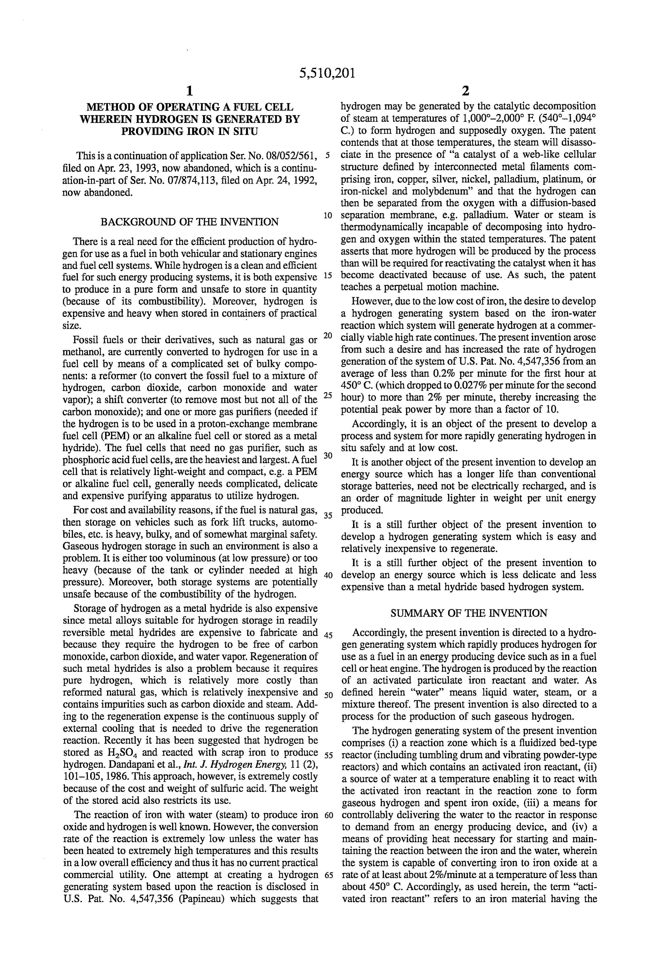
METHOD OF OPERATING A FUEL CELL hydrogen may be generated by the catalytic decomposition WHEREEN HYDROGEN IS GENERATED BY of steam at temperatures of 1,000-2,000 F (540°-1,094 PROVIDENG RON IN STU C.) to form hydrogen and supposedly oxygen. The patent contends that at those temperatures, the steam will disasso
This is a continuation of application Ser. No. 08/052/561, ciate in the presence of "a catalyst of a web-like cellular filed on Apr. 23, 1993, now abandoned, which is a continu structure defined by interconnected metal filaments com ation-in-part of Ser. No. 07/874,113, filed on Apr. 24, 1992, prising iron, copper, silver, nickel, palladium, platinum, or now abandoned. iron-nickel and molybdenum' and that the hydrogen can then be separated from the oxygen with a diffusion-based
BACKGROUND OF THE INVENTION
O separation membrane, e.g. palladium. Water or steam is thermodynamically incapable of decomposing into hydro
There is a real need for the efficient production of hydro gen and oxygen within the stated temperatures. The patent gen for use as a fuel in both vehicular and stationary engines asserts that more hydrogen will be produced by the process and fuel cell systems. While hydrogen is a clean and efficient than will be required for reactivating the catalyst when it has fuel for such energy producing systems, it is both expensive 15 become deactivated because of use. As such, the patent to produce in a pure form and unsafe to store in quantity teaches a perpetual motion machine. (because of its combustibility). Moreover, hydrogen is However, due to the low cost of iron, the desire to develop expensive and heavy when stored in containers of practical a hydrogen generating system based on the iron-water SZ. reaction which system will generate hydrogen at a commer Fossil fuels or their derivatives, such as natural gas or 20 cially viable high rate continues. The present invention arose methanol, are currently converted to hydrogen for use in a from such a desire and has increased the rate of hydrogen fuel cell by means of a complicated set of bulky compo generation of the system of U.S. Pat. No. 4,547,356 from an nents: a reformer (to convert the fossil fuel to a mixture of average of less than 0.2% per minute for the first hour at hydrogen, carbon dioxide, carbon monoxide and water 25 450° C. (which dropped to 0.027% perminute for the second vapor); a shift converter (to remove most but not all of the hour) to more than 2% per minute, thereby increasing the carbon monoxide); and one or more gas purifiers (needed if potential peak power by more than a factor of 10. the hydrogen is to be used in a proton-exchange membrane Accordingly, it is an object of the present to develop a fuel cell (PEM) or an alkaline fuel cell or stored as a metal process and system for more rapidly generating hydrogen in hydride). The fuel cells that need no gas purifier, such as 30 situ safely and at low cost.
phosphoric acid fuel cells, are the heaviest and largest. A fuel It is another object of the present invention to develop an cell that is relatively light-weight and compact, e.g. a PEM energy source which has a longer life than conventional or alkaline fuel cell, generally needs complicated, delicate storage batteries, need not be electrically recharged, and is and expensive purifying apparatus to utilize hydrogen. an order of magnitude lighter in weight per unit energy For cost and availability reasons, if the fuel is natural gas, 35 produced.
then storage on vehicles such as fork lift trucks, automo It is a still further object of the present invention to biles, etc. is heavy, bulky, and of somewhat marginal safety. develop a hydrogen generating system which is easy and Gaseous hydrogen storage in such an environment is also a relatively inexpensive to regenerate. problem. It is either too voluminous (at low pressure) or too It is a still further object of the present invention to heavy (because of the tank or cylinder needed at high 40 develop an energy source which is less delicate and less pressure). Moreover, both storage systems are potentially expensive than a metal hydride based hydrogen system. unsafe because of the combustibility of the hydrogen.
Storage of hydrogen as a metal hydride is also expensive SUMMARY OF THE INVENTION since metal alloys suitable for hydrogen storage in readily reversible metal hydrides are expensive to fabricate and 45 Accordingly, the present invention is directed to a hydro because they require the hydrogen to be free of carbon gen generating system which rapidly produces hydrogen for monoxide, carbon dioxide, and water vapor. Regeneration of use as a fuel in an energy producing device such as in a fuel such metal hydrides is also a problem because it requires cellor heat engine. The hydrogen is produced by the reaction pure hydrogen, which is relatively more costly than of an activated particulate iron reactant and water. As reformed natural gas, which is relatively inexpensive and 50 defined herein “water” means liquid water, steam, or a contains impurities such as carbon dioxide and steam. Add mixture thereof. The present invention is also directed to a ing to the regeneration expense is the continuous supply of process for the production of such gaseous hydrogen. external cooling that is needed to drive the regeneration The hydrogen generating system of the present invention reaction. Recently it has been suggested that hydrogen be comprises (i) a reaction zone which is a fluidized bed-type stored as HSO and reacted with scrap iron to produce 55 reactor (including tumbling drum and vibrating powder-type hydrogen. Dandapani et al., Int. J. Hydrogen Energy, 11 (2), reactors) and which contains an activated iron reactant, (ii) 101-105, 1986. This approach, however, is extremely costly a source of water at a temperature enabling it to react with because of the cost and weight of sulfuric acid. The weight the activated iron reactant in the reaction zone to form of the stored acid also restricts its use. gaseous hydrogen and spent iron oxide, (iii) a means for The reaction of iron with water (steam) to produce iron 60 controllably delivering the water to the reactor in response oxide and hydrogenis well known. However, the conversion to demand from an energy producing device, and (iv) a rate of the reaction is extremely low unless the water has means of providing heat necessary for starting and main been heated to extremely high temperatures and this results taining the reaction between the iron and the water, wherein in a low overall efficiency and thus it has no current practical the system is capable of converting iron to iron oxide at a commercial utility. One attempt at creating a hydrogen 65 rate of at least about 2%/minute at a temperature of less than generating system based upon the reaction is disclosed in about 450° C. Accordingly, as used herein, the term "acti U.S. Pat. No. 4,547,356 (Papineau) which suggests that vated iron reactant” refers to an iron material having the
Page 3
capacity of converting at least about 2% of the iron per water, generally for conversion into heated water or steam. minute into iron oxide at a temperature of about 840 F. In addition, the system contains a means for controllably (450° C.) or less. delivering the water to the reactor in response to a demand The reaction which takes place in the reactor produces from an energy producing device and means for providing hydrogen and iron oxide. The system can be easily and heat necessary for starting-up and maintaining the reaction between the heated water and the activated iron reactant.
inexpensively recharged by converting the iron oxide back Although generally the water will be heated to form steam, to iron and replenishing the water. Although the reformation when a sufficiently active activated iron reactant is used or of the spent iron oxide could take place anywhere by use of when a low flow of hydrogen is required, this may not be relatively small reforming units, most commonly it will necessary.
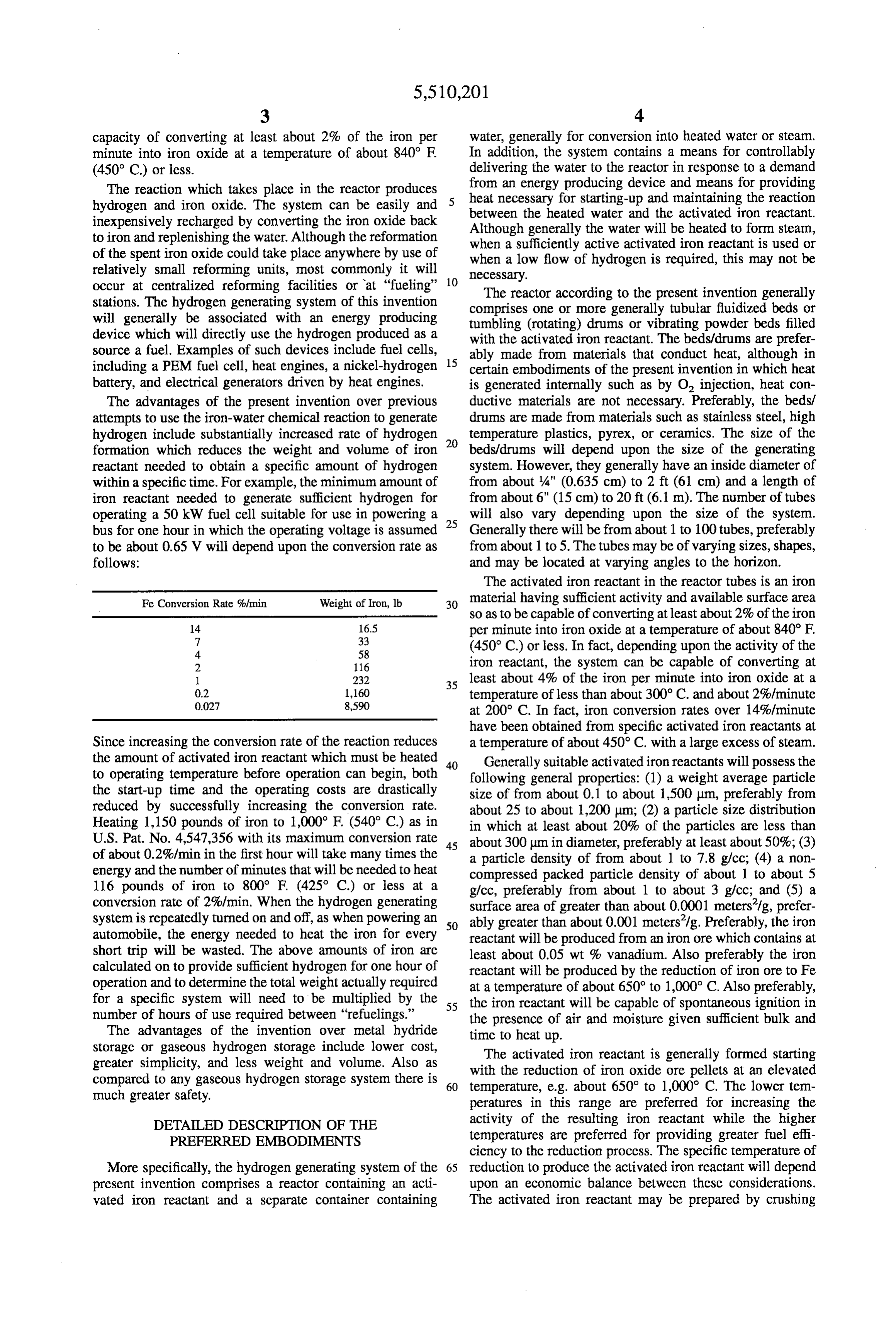
occur at centralized reforming facilities or at "fueling' 10 The reactor according to the present invention generally stations. The hydrogen generating system of this invention comprises one or more generally tubular fluidized beds or will generally be associated with an energy producing tumbling (rotating) drums or vibrating powder beds filled device which will directly use the hydrogen produced as a with the activated iron reactant. The beds/drums are prefer source a fuel. Examples of such devices include fuel cells, 15 ably made from materials that conduct heat, although in including a PEM fuel cell, heat engines, a nickel-hydrogen certain embodiments of the present invention in which heat battery, and electrical generators driven by heat engines. is generated internally such as by O injection, heat con The advantages of the present invention over previous ductive materials are not necessary. Preferably, the beds/ attempts to use the iron-water chemical reaction to generate drums are made from materials such as stainless steel, high hydrogen include substantially increased rate of hydrogen 20 temperature plastics, pyrex, or ceramics. The size of the formation which reduces the weight and volume of iron beds/drums will depend upon the size of the generating reactant needed to obtain a specific amount of hydrogen system. However, they generally have an inside diameter of within a specific time. For example, the minimum amount of from about 4" (0.635 cm) to 2 ft (61 cm) and a length of iron reactant needed to generate sufficient hydrogen for from about 6" (15 cm) to 20 ft (6.1 m). The number of tubes operating a 50 kW fuel cell suitable for use in powering a 25 will also vary depending upon the size of the system. bus for one hour in which the operating voltage is assumed Generally there will be from about 1 to 100 tubes, preferably to be about 0.65 V will depend upon the conversion rate as from about 1 to 5. The tubes may be of varying sizes, shapes, follows: and may be located at varying angles to the horizon. The activated iron reactant in the reactor tubes is an iron
Fe Conversion Rate %imin Weight of Iron, lb 30 material having sufficient activity and available surface area so as to be capable of converting at least about 2% of the iron
per minute into iron oxide at a temperature of about 840 F.
(450° C.) or less. In fact, depending upon the activity of the 2 116 iron reactant, the system can be capable of converting at 1. 232 35 least about 4% of the iron per minute into iron oxide at a
temperature of less than about 300° C. and about 2%/minute at 200° C. In fact, iron conversion rates over 14%/minute have been obtained from specific activated iron reactants at
Since increasing the conversion rate of the reaction reduces a temperature of about 450° C. with a large excess of steam. the amount of activated iron reactant which must be heated 40 Generally suitable activated iron reactants will possess the to operating temperature before operation can begin, both following general properties: (1) a weight average particle the start-up time and the operating costs are drastically size of from about 0.1 to about 1,500 um, preferably from reduced by successfully increasing the conversion rate. about 25 to about 1,200 um; (2) a particle size distribution Heating 1,150 pounds of iron to 1,000 F (540° C.) as in in which at least about 20% of the particles are less than U.S. Pat. No. 4,547,356 with its maximum conversion rate 45 about 300 m in diameter, preferably at least about 50%; (3) of about 0.2%/min in the first hour will take many times the a particle density of from about 1 to 7.8 g/cc; (4) a non energy and the number of minutes that will be needed to heat compressed packed particle density of about 1 to about 5 116 pounds of iron to 800° F (425° C.) or less at a g/cc, preferably from about 1 to about 3 g/cc; and (5) a conversion rate of 2%/min. When the hydrogen generating surface area of greater than about 0.0001 meters/g, prefer system is repeatedly turned on and off, as when powering an 50 ably greater than about 0.001 meters'/g. Preferably, the iron automobile, the energy needed to heat the iron for every reactant will be produced from an iron ore which contains at short trip will be wasted. The above amounts of iron are least about 0.05 wt % vanadium. Also preferably the iron calculated on to provide sufficient hydrogen for one hour of reactant will be produced by the reduction of iron ore to Fe operation and to determine the total weight actually required at a temperature of about 650 to 1,000°C. Also preferably, for a specific system will need to be multiplied by the 55 the iron reactant will be capable of spontaneous ignition in number of hours of use required between "refuelings.” the presence of air and moisture given sufficient bulk and The advantages of the invention over metal hydride time to heat up.
storage or gaseous hydrogen storage include lower cost, The activated iron reactant is generally formed starting greater simplicity, and less weight and volume. Also as with the reduction of iron oxide ore pellets at an elevated compared to any gaseous hydrogen storage system there is 60 temperature, e.g. about 650 to 1,000° C. The lower tem much greater safety. peratures in this range are preferred for increasing the DETALED DESCRIPTION OF THE activity of the resulting iron reactant while the higher PREFERRED EMBODEMENTS temperatures are preferred for providing greater fuel effi ciency to the reduction process. The specific temperature of
More specifically, the hydrogen generating system of the 65 reduction to produce the activated iron reactant will depend present invention comprises a reactor containing an acti upon an economic balance between these considerations. vated iron reactant and a separate container containing The activated iron reactant may be prepared by crushing
Page 4
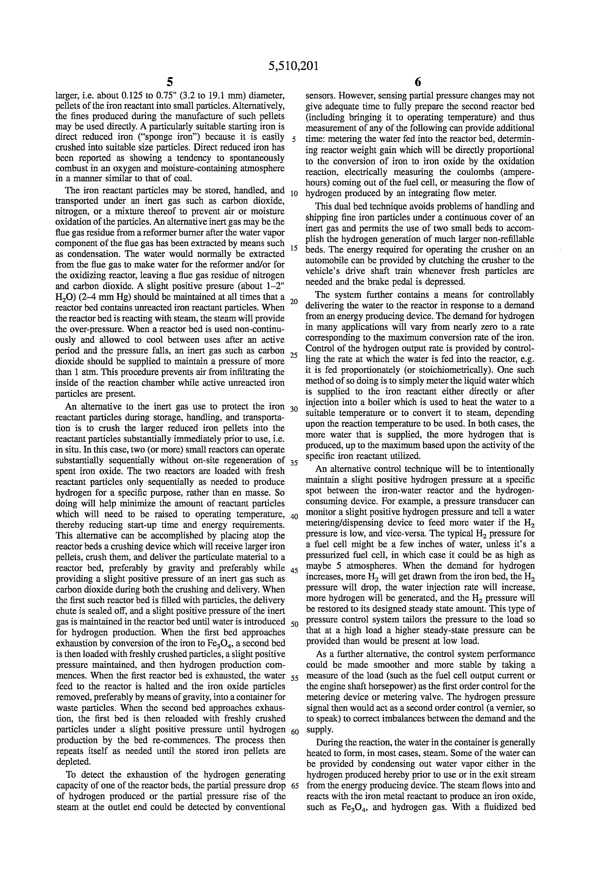
S 6 larger, i.e. about 0.125 to 0.75" (3.2 to 19.1 mm) diameter, sensors. However, sensing partial pressure changes may not pellets of the iron reactant into small particles. Alternatively, give adequate time to fully prepare the second reactor bed the fines produced during the manufacture of such pellets (including bringing it to operating temperature) and thus may be used directly. A particularly suitable starting iron is measurement of any of the following can provide additional direct reduced iron ("sponge iron') because it is easily time: metering the water fed into the reactor bed, determin crushed into suitable size particles. Direct reduced iron has ing reactor weight gain which will be directly proportional been reported as showing a tendency to spontaneously to the conversion of iron to iron oxide by the oxidation combust in an oxygen and moisture-containing atmosphere reaction, electrically measuring the coulombs (ampere in a manner similar to that of coal. hours) coming out of the fuel cell, or measuring the flow of The iron reactant particles may be stored, handled, and 10 hydrogen produced by an integrating flow meter. transported under an inert gas such as carbon dioxide, This dual bed technique avoids problems of handling and nitrogen, or a mixture thereof to prevent air or moisture shipping fine iron particles under a continuous cover of an oxidation of the particles. An alternative inert gas may be the flue gas residue from a reformer burner after the water vapor inert gas and permits the use of two small beds to accom component of the flue gas has been extracted by means such 5 beds.plish the hydrogen generation of much larger non-refillable as condensation. The water would normally be extracted The energy required for operating the crusher on an from the flue gas to make water for the reformer and/or for automobile can be provided by clutching the crusher to the the oxidizing reactor, leaving a flue gas residue of nitrogen vehicle's drive shaft train whenever fresh particles are and carbon dioxide. A slight positive presure (about 1-2" needed and the brake pedal is depressed. HO) (2-4 mm Hg) should be maintained at all times that a 20 The system further contains a means for controllably reactor bed contains unreacted iron reactant particles. When delivering the water to the reactor in response to a demand the reactorbed is reacting with steam, the steam will provide from an energy producing device. The demand for hydrogen the over-pressure. When a reactor bed is used non-continu in many applications will vary from nearly zero to a rate ously and allowed to cool between uses after an active corresponding to the maximum conversion rate of the iron. period and the pressure falls, an inert gas such as carbon 25 Control of the hydrogen output rate is provided by control dioxide should be supplied to maintain a pressure of more ling the rate at which the water is fed into the reactor, e.g. than 1 atm. This procedure prevents air from infiltrating the it is fed proportionately (or stoichiometrically). One such inside of the reaction chamber while active unreacted iron method of so doing is to simply meter the liquid water which particles are present. is supplied to the iron reactant either directly or after An alternative to the inert gas use to protect the iron 30 injection into a boiler which is used to heat the water to a suitable temperature or to convert it to steam, depending reactant particles during storage, handling, and transporta tion is to crush the larger reduced iron pellets into the upon the reaction temperature to be used. In both cases, the reactant particles substantially immediately prior to use, i.e. more water that is supplied, the more hydrogen that is in situ. In this case, two (or more) small reactors can operate produced, up to the maximum based upon the activity of the substantially sequentially without on-site regeneration of 35 specific iron reactant utilized.
spent iron oxide. The two reactors are loaded with fresh An alternative control technique will be to intentionally reactant particles only sequentially as needed to produce maintain a slight positive hydrogen pressure at a specific hydrogen for a specific purpose, rather than en masse. So spot between the iron-water reactor and the hydrogen doing will help minimize the amount of reactant particles consuming device. For example, a pressure transducer can which will need to be raised to operating temperature, 40 monitor a slight positive hydrogen pressure and tell a water thereby reducing start-up time and energy requirements. metering/dispensing device to feed more water if the H. This alternative can be accomplished by placing atop the pressure is low, and vice-versa. The typical H, pressure for reactor beds a crushing device which will receive larger iron a fuel cell might be a few inches of water, unless it's a pellets, crush them, and deliver the particulate material to a pressurized fuel cell, in which case it could be as high as reactor bed, preferably by gravity and preferably while 45 maybe 5 atmospheres. When the demand for hydrogen providing a slight positive pressure of an inert gas such as increases, more H will get drawn from the iron bed, the H. carbon dioxide during both the crushing and delivery. When pressure will drop, the water injection rate will increase, the first such reactor bed is filled with particles, the delivery more hydrogen will be generated, and the H pressure will chute is sealed off, and a slight positive pressure of the inert be restored to its designed steady state amount. This type of gas is maintained in the reactor bed until water is introduced 50 pressure control system tailors the pressure to the load so for hydrogen production. When the first bed approaches that at a high load a higher steady-state pressure can be exhaustion by conversion of the iron to FeO, a second bed provided than would be present at low load. is then loaded with freshly crushed particles, a slight positive As a further alternative, the control system performance pressure maintained, and then hydrogen production com could be made smoother and more stable by taking a mences. When the first reactor bed is exhausted, the water 55 measure of the load (such as the fuel cell output current or feed to the reactor is halted and the iron oxide particles the engine shaft horsepower) as the first order control for the removed, preferably by means of gravity, into a container for metering device or metering valve. The hydrogen pressure waste particles. When the second bed approaches exhaus signal then would act as a second order control (a vernier, so tion, the first bed is then reloaded with freshly crushed to speak) to correct imbalances between the demand and the particles under a slight positive pressure until hydrogen 60 Supply.
production by the bed re-commences. The process then During the reaction, the water in the container is generally repeats itself as needed until the stored iron pellets are heated to form, in most cases, steam. Some of the water can depleted. be provided by condensing out water vapor either in the To detect the exhaustion of the hydrogen generating hydrogen produced hereby prior to use or in the exit stream capacity of one of the reactor beds, the partial pressure drop 65 from the energy producing device. The steam flows into and of hydrogen produced or the partial pressure rise of the reacts with the iron metal reactant to produce an iron oxide, steam at the outlet end could be detected by conventional such as FeO, and hydrogen gas. With a fluidized bed
Page 5
reactor, the flow of steam will lift and suspend the particles. weight and complexity of an on-board reformer, such a To initiate the reaction, start-up heat is needed to create reduction system is not considered desirable for automotive steam from the water. This heat may be provided by a variety type uses. When oxidation temperatures greater than about of suitable means, such as by injecting heated water and air 300° C. are used, complications in terms of materials, into a reactor zone to rapidly oxidize the iron reactant. thermal insulation, and initial heat-up time can occur, mak Hydrogen will generally not be produced by the reaction ing those temperatures somewhat less suitable for use on a with the air present, but heat will be and the heat produced vehicle. In such cases it may be advantageous to add a is greater and the heat-up potentially faster than when the catalyst to lower the hydrogen overpotential of the iron iron reacts with steam alone to form hydrogen. Additionally, reactant in the presence of water or steam to more moderate a catalytic or ordinary burning of the hydrogen produced by 10 temperatures, e.g. about 50° to 150° C. The lower hydrogen the injected water and air may be used to help heat the iron overpotential means that the kinetics of the reaction will be reactant up to the temperature needed to initiate reaction. A improved, thus allowing the reaction to take place at a lower further source of the start-up heat is the burning of a temperature and lessening strains on the system. Suitable conventional fuel such as compressed natural gas, propane, catalysts for use to improve reaction kinetics are likely to or gasoline in a separate burner, employing a suitable means 5 include noble metals such as platinum to transport the heat generated. A further potential source of as base metals such as antimony. and palladium as well start-up heat is a storage battery disposed within or adjacent When used, a catalyst may be added to the system by to the energy producing device. mixing it as a powder with the particulate activated iron A more complex scheme for supplying start-up heat to the reactant. Alternatively, the catalyst may be galvanically reactor Zone is to employ a plurality of reactor beds in the 20 linked to the iron reactant via an electrolyte dissolved in the reaction Zone with either one smaller reactor bed or a series water of reaction and an electrical contact between a cata of beds of graduated sizes. First, the smallestbed is brought lyzed sheet or basket and the iron reactant. Suitable elec up to operating temperature with a battery or a small burner. trolytes include aqueous solutions of ferrous sulfate, ferric Then the hydrogen it produces is burned with air to form sulfate, sodium sulfate, potassium sulfate. Sodium sulfate is water and to heat up the larger reactor beds. In the case of 25 presently preferred because it is neutral and does not react graduated sized beds, the hydrogen produced by the next with either Fe or FeO. With enough catalyst and good larger bed may be used to heat up the next even larger bed. catalyst geometry, temperatures as low as 0° C. may be all The vaporization of the water of reaction into steam may that are needed to initiate and maintain the reaction. In such be achieved by any conventional heating means. For cases the water would be simply transferred to the reaction example, heat may be supplied by transferring waste heat 30 Zone by suitable means such as pumping and gravity feed. from an energy producing device, e.g. the fuel cell or heat Because of relatively high catalyst costs as compared to engine, to which the hydrogen generator of this invention is activated iron reactant costs, the lowering of the temperature associated, to the water to vaporize it. In the case of a PEM as far as possible may not be economically the most sensible fuel cell, the waste heat is generally at about 90° C., a design. The cost of the catalyst must be balanced with the temperature which may be too low for a hydrogen generat 35 reaction kinetics. Generally, a system sufficient to provide an ing system running at ambient atmospheric pressure, but this operating temperature of from about 80°C. to about 300° C. can be overcome by mixing the subatmospheric steam will be preferred.
produced at circa 90° C. with some of the hydrogen pro In order to avoid the cost of alloying or mixing a catalyst duced by the energy-producing system on discharge. with the iron reactant, certain catalysts may be added Together, the two gases will have a total pressure of one 40 directly to the water of reaction as soluble metal compounds. atmosphere absolute, allowing the vaporization of the water Examples of such soluble metal compounds are noble metal to proceed at a partial water vapor pressure of less than one compounds such as platinic acid or any chloroplatinate. The atmosphere. catalyst is added to the water of reaction as a soluble If the discharge rate of the fuel cell or engine is so low that compound such as potassium chloroplatinate. The interac the reactor beds tend to cool down or an endotherm is 45 tion between the iron reactant with the water of reaction and needed to adequately maintain the reaction, a variable and with the soluble compound causes the iron reactant to be controlled amount of air or oxygen may be injected into the catalyzed for faster reaction with water when forming iron reactant bed during the discharge reaction with steam. hydrogen and iron oxide. It is believed that this technique This will allow maintenance of a higher reaction tempera may enable the metal catalyst to come into permanent ture. 50 contact with the iron reactant, lowering its hydrogen over While the temperature of the reaction may be any tem potential and accelerating the generation of hydrogen at perature generally above about 0°C., generally the reaction relatively
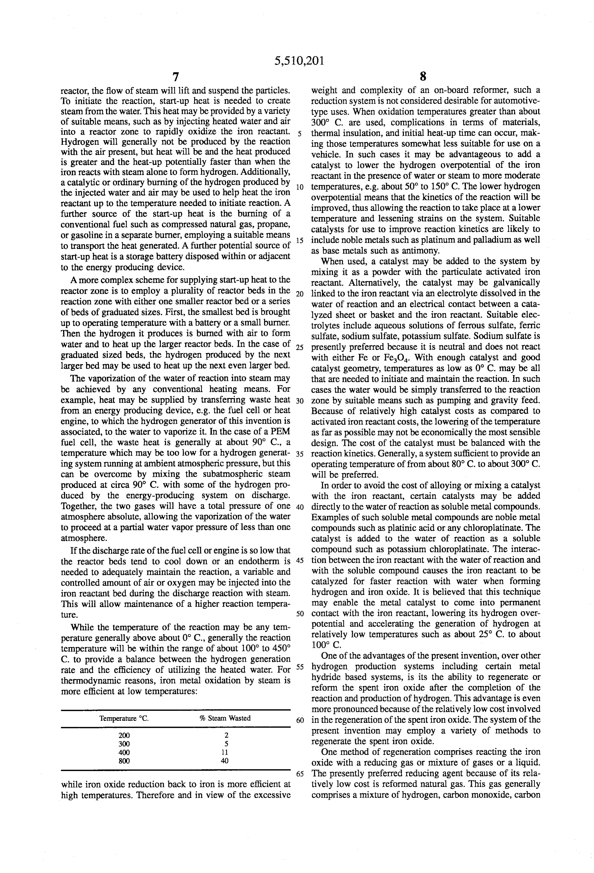
low temperatures such as about 25 C. to about temperature will be within the range of about 100° to 450 One of the advantages of the present invention, over other C. to provide a balance between the hydrogen generation 55 hydrogen production systems including certain metal rate and the efficiency of utilizing the heated water. For hydride based systems, is its the ability to regenerate or thermodynamic reasons, iron metal oxidation by steam is reform the spent iron oxide after the completion of the more efficient at low temperatures:
reaction and production of hydrogen. This advantage is even more pronounced because of the relatively low cost involved
Temperature C. % Steam Wasted 60 in the regeneration of the spent iron oxide. The system of the 200 2 present invention may employ a variety of methods to 300 5 regenerate the spent iron oxide.
400 1. One method of regeneration comprises reacting the iron 800 40 oxide with a reducing gas or mixture of gases or a liquid. 65 The presently preferred reducing agent because of its rela while iron oxide reduction back to iron is more efficient at tively low cost is reformed natural gas. This gas generally high temperatures. Therefore and in view of the excessive comprises a mixture of hydrogen, carbon monoxide, carbon
Page 6
9 O dioxide, and residual steam. While hydrogen and carbon and a drier resulting mixture is then fed to the next stage of monoxide are the only active reducing agents, the iron/iron the iron oxide-to-iron regenerator. The vent gas of the oxide bed being regenerated is not damaged by the presence second stage can then be burned to provide the needed of the other two components. If hydrogen gas is available at endotherms and the overall efficiency would be better than a lower cost than reformed natural gas, it could be used, that of a single stage regenerator. Alternatively, only one provided that heat is added to the reaction which is some condensing stage may be used but at a lower efficiency. what endothermic. Relatively pure carbon monoxide, where For a vehicle-mounted system, the reformation process available, can also be used as a reducing agent. It, however, will preferably be performed at a location away from the would contribute about four to five times more carbon energy producing device, including at central plants which dioxide to the greenhouse effect than reformed natural gas 10 receive spent material from numerous sources. Generally, and it is more exothermic than needed to sustain the reac the spent iron oxide particles will be pelletized to form tion, thus it is less efficient. The gaseous reducing agents relatively large, i.e. about 0.125 to 0.75" (3.2 to 19.1 mm), may be supplied as a reformed liquid fuel such as reformed pellets diameter pellets of the iron oxide and then reducing the to iron metal. Thereafter, the pellets will be crushed methanol, reformed ethanol, reformed petroleum deriva into the appropriate size activated iron reactant particles for tives, and reformed or decomposed ammonia. 15 re-use. The iron and iron oxides may be transferred to and
The reformed fuels may be derived by various techniques from refueling stations both near and distant from the site of including: via steam-reforming (wherein the fuel in gaseous the energy producing device. The recycling of the metal form is reacted with steam); via partial oxidation (wherein reactant can theoretically occur an infinite number of times the fuel is reacted with oxygen or air in proportions less than in view of the use of the particulate iron reactant, although that needed for complete oxidation); or via autothermal 20 some crushing or grinding of agglomerated materials may be reforming (wherein the fuel is partially reacted with steam beneficial between cycles, even if the iron oxide particles are and partially with oxygen or air). Steam reforming is more not pelletized prior to regeneration. efficient than partial oxidation in terms of yield of hydrogen An alternative to using a relatively large and removed per unit of fuel. While steam reforming is endothermic central processing facility for reforming the spent metal (requires externally supplied heat to sustain itself) and while 25 oxide is to use smaller reformer units at the site of the energy partial oxidation is exothermic (yields heat), autothermal producing device, e.g. at a refueling station. As with the reforming is intermediate between steam reforming and centralized reforming unit, the on-site reforming units may partial oxidation with regard to both hydrogenyield and heat be used to convert the spent iron oxide to iron reactant as addition/removal. The selection of a particular reforming described previously using, for example, reformed natural process will thus be made based upon factors which include 30 gas. The reduced iron may then be reused to generate hydrogen yield required, equipment costs and complexity, hydrogen immediately or stored for such use at a later time. overall process heat requirements, and the like for the As an alternative to directly using the iron-water reaction particular operation. to produce hydrogen which is directly used as a fuel for such Since the reduction reaction of iron oxide by hydrogen to as a fuel cell or engine, the hydrogen may be stored in a form iron is generally endothermic, taking place at about 35 metal hydride storage bed. Since the hydrogen produced in 700 to 1,100° C., heat must be supplied. One method is to accordance with this procedure is slightly wet, the hydrogen inject air or oxygen into a reactor bed, so that some of the will need to be dried, such as by passing it through a reducing agent burns and thereby heats up the regeneration desiccant. Then the dried hydrogen can be conveyed to and reaction zone, i.e. autothermal reforming. Another method is absorbed in a metal hydride bed (or some other storage to burn the vent gas from the hydrogen producing reaction 40 device) for later use. To store the hydrogen as a metal and transfer its heat of combustion to the regeneration hydride, it is directly reacted with a metal or metal alloy such reaction Zone through the walls of the reactor. Still another as iron-titanium, nickel-lanthanum, or nickel-calcium. Pres method is to burn part of the reducing agent upstream of the sure may have to be applied and heat may have to be reforming device and transfer the heat of combustion across removed from the metal hydride bed to sustain the exother the reactor bed walls of the ironfiron oxide containing 45 mic reaction at a desirably low reaction pressure. The heat reactor. Another approach is to make the reaction of the can be removed, for example, (i) by recirculating part of the reducing agent and the iron oxide exothermic. This can be hydrogen that enters the metal hydride bed and cooling it accomplished by maintaining enough carbon monoxide in before it mixes with fresh hydrogen from the metal-steam the reducing gas mixture to make the sum of the reduction bed or (ii) by using a separate heat transfer medium, such as reactions slightly exothermic. 50 a liquid or gaseous coolant, to keep the metal hydride Still another scheme for supplying the necessary heat to container and its contents adequately cool. The metal maintain the regenerating reaction is to burn vent gas from hydride thus formed becomes a direct source of hydrogen another near-by regenerating bed. This vent gas normally which may be used for powering a fuel cell or engine with contains a mixture of unused hydrogen, steam, carbon the iron reactant-water reaction of the invention being an monoxide, carbon dioxide, and unreacted reformate. Some 55 indirect source of said hydrogen. This procedure may be of the unreacted reducing mixture can be utilized in a particularly applicable during the start-up or heat-up period. reformer burner to compensate for the endothermic nature of An alternative means for providing additional hydrogen the steam reforming reaction and that of the reducing during start-up or heat-up is to simply provide a small process if hydrogen prevails in the reformate. The rest is amount of stored hydrogen at ambient or near-ambient truly wasted. To minimize this, two separate reduction stages 60 pressure in a storage device. Once the energy using device in series, each preceded by a water-removing condenser, is at temperature and fully operative, some fresh hydrogen may be used. The condenser upstream of the first reducing can be diverted by means of a solenoid valve controlled by stage removes water from the reformate and the condenser a pressure sensor or pressure switch from its principal load upstream of the second reducing stage removes water from to replenish the storage device, be it pressurized or not. In the first stage exhaust. With less water coming into a 65 this case, the hydrogen storage device acts like the storage subsequent reducing stage, less unused hydrogen will come battery in an automobile, supplying energy during start-up out in the end. Thus water is condensed out of the vent gas and absorbing it during normal driving for later use.
Page 7
The system is associated with an energy producing device process is the lack of any need for upgrading or purifying the which uses the hydrogen produced from the reaction resulting reformate gas. The resulting reformate reduces the between the water and activated iron reactant as a fuel. The iron oxide to the metallic state. Simultaneously in a second reactor and water container may either be located outside of iron/iron oxide bed which is then in the metallic state, the the energy producing device or self-contained therein, 5 iron is reacted with steam to produce moist hydrogen. The depending upon the particular device and end-use thereof. moist hydrogen is delivered to a fuel cell or other hydrogen Such energy producing devices include fuel cells, such as powered device. The dual bed reductive regeneration/hy. PEM fuel cells, and heat engines, such as internal or external drogen generation system can be highly integrated with the combustion engines. The heat engine may be a free standing reformer from a thermal standpoint to maximize the energy efficiency of the overall process. The process can then engine or one that mechanically drives an electrical genera 10 continue tor or alternator. indefinitely with the dual beds being cycled at The hydrogen generating system produces wet, slightly suitable frequencies through the use of solenoid valves or wet, or nearly dry hydrogen, depending upon the tempera the like. The dual bed system is particularly suitable for proton-exchange membrane and alkaline fuel cells which ture of the iron oxidation reaction and the presence or operate efficiently and at very high power densities on moist absence of a water condenser to remove water from the 15 hydrogen fuel.
output hydrogen stream. When this hydrogen is used to fuel During regeneration of the spent iron oxide, the reformed a heat engine, the exhaust from the engine will contain natural gas may contain sulfur impurities, which may accu neither carbon monoxide nor hydrocarbons. The exhaust can mulate in the bed over many regeneration cycles. The sulfur also be freed of NO, either by injecting more hydrogen than will react with the iron reactant creating iron sulfides. The is needed to react stoichiometrically with the injected air (a 20 iron sulfides might not be decomposed either by steam on rich combustion mix) or by injecting hydrogen into the discharge or by fuel or reformate in recharge. This will engine exhaust stream at a temperature equal to or lower eventually tie up irreversibly a large fraction of the iron than the initial exhaust temperature or by some combination reactant bed as iron sulfides instead, preventing it from of the two. The first scheme suppresses NO by reacting it switching from iron oxide to elemental iron. In order to with hydrogen before it can build to an appreciable concen 25 overcome this contamination problem, unwanted iron sul tration in the engine or exhaust manifold while the second fide FeS can be converted to sulfur dioxide (SO) or ferrous burns the secondary hydrogen using any NO present in the sulfate (FeSO)and some iron oxide by briefly, e.g. 1-15 exhaust as the oxidant. minutes, passing a stream of air over the heated bed of spent For automotive use in particular, especially in urban or iron oxide before that bed is reduced to elemental iron. Any slow suburban traffic, a combination of two hydrogen fueled 30 accumulation of FeSO can be removed by washing the vehicle drive systems may be advantageous. The first would particles with water to dissolve it prior to regeneration. Since be an electric motor powered by a hydrogen fuel cell and the the bed must be heated to regenerate it, little or no additional second would be a hydrogen fueled engine. The dual com heating is needed to remove the iron sulfide by hot air bination will use less fuel than a hydrogen engine operating oxidation. The transition from air to reformate or fuel alone and could cost less than a fuel cell-based drive sized 35 through the bed can be made safe against explosion by to generate the average vehicle power by itself. A hybrid briefly purging the bed with carbon dioxide, steam, nitrogen, scheme of fuel cell and engine, possibly using a third or any other suitable inert gas. In particular, a mixture of component (such as a battery, a flywheel or an ultracapaci steam and CO, from another bed being regenerated is a tor) for surges, is especially suited for the hydrogen genera readily available, essentially cost-free purging agent. tor system since it can supply hydrogen for both drives. The 40 What is claimed is:
hybrid scheme will have the potential of producing zero 1. A method of operating a hydrogen-air fuel cell that is exhaust pollutants and Zero tank emissions. At idle and in fed by the in situ generation of hydrogen, which hydrogen slow or downhill traffic when the motive power input is generated by passing H2O into contact with ground or required is low or even negative, the hydrogen combustion crushed iron, said iron being ground or crushed in situ to engine can be shut off allowing the fuel cell-powered electric 45 enhance its activity and used in a reaction with said HO motor to alone propel the vehicle. On down-slopes, the within an operative cycle after grinding or crushing, said engine could free-wheel without a fuel input so that at the method comprising the steps of:
bottom of the hill it could immediately start generating (a) providing a fluidized bed of iron, said iron being traction withoutfirst having to rev up to driving speed. There initially in a pellet form prior to grinding or crushing in will be a substantial fuel savings from so doing because a 50 order to supply iron particles for said fluidized bed, and combustion engine uses much more fuel at part load and idle a source of H2O in combination with a hydrogen-air than does a fuel cell. As power demands increase, the engine fuel cell;
can turn on and be automatically clutched to the car's (b) generating hydrogen for said hydrogen-air fuel cell by transmission and final drive so that both the engine and the reacting said iron with said H2O at an approximate electric motor propel the vehicle. This hybrid system will 55 maximum temperature of about 450° C.; enable the fuel cell, with its high capital cost per unit power, (c) grinding or crushing said iron to produce active iron to be sized to a fraction of the average vehicle power particles, whose reactivity is enhanced to generate demand, yet allow shut-off of the engine at low power or idle hydrogen in step (b) at a rate of approximately at least when it would consume far more fuel than a fuel cell.
When a reduced iron is to be immediately used as a fuel 60 two percent per minute (2%/min.) at said approximate source in a hydrogen powered on-site device, a suitable maximum temperature of about 450° C., said grinding system may entail a cyclic operation of at least two iron/iron or crushing being accomplished in situ within an opera oxide beds. In such a system, the net effect will be entrance tive cycle of said hydrogen-air fuel cell; of a selected fuel into a reforming process and output of (d) supplying said hydrogen generated in step (b) to said moist hydrogen. The fuel to the reforming process can be 65 hydrogen-air fuel cell; virtually any hydrocarbon species or mixtures thereof (e) generating H2O and electricity in said hydrogen-air including an alcohol. A particular advantage of the present fuel cell; and
Page 8
(f) using at least some of the HO generated in step (e) to (c) grinding or crushing said iron to produce active iron resupply HO for the generation of hydrogen in step particles, whose reactivity is enhanced to generate (b). hydrogen in step (b) at a rate of approximately at least 2. The method in accordance with claim 1, further com two percent per minute (2%/min.) at said approximate prising the step of: maximum temperature of about 450° C., said grinding (g) grinding or crushing said iron in pellet form in or crushing being accomplished in situ within an opera accordance with the grinding or crushing step (c) to tive cycle of said hydrogen-air fuel cell; provide particles of iron in a particle size having a (d) supplying said hydrogen generated in step (b) to said range from approximately 0.1 to 1,500 um. hydrogen-air fuel cell;
3. The method in accordance with claim 1, further com 10 prising the step of: (e) generating H2O and electricity in said hydrogen-air (g) supplying heat to the reaction between the HO and fuel cell; and the iron in step (b) for starting the reaction between the (f) using at least some of the HO generated in step (e) to HO and said iron. resupply HO for the generation of hydrogen in step 4. The method in accordance with claim 2, further com 15 (b).
prising the step of: 7. The method in accordance with claim 6, further com (h) grinding or crushing said iron in pellet form in prising the step of:
accordance with the grinding or crushing step (c) to (g) grinding or crushing said iron in accordance with the provide iron in a particle size having a particle size 20 grinding or crushing step (c) to provide particles of iron distribution range in which at least twenty percent in a particle size having a range from approximately 0.1 (20%) of the particles are less than approximately 300 to 1,500 um.
um in diameter. 8. The method in accordance with claim 6, further com 5. The method in accordance with claim 2, further con prising the step of:
prising the step of: 25 (g) supplying heat to the reaction between the H2O and (h) providing particles of iron in accordance with the the iron in step (b) for starting the reaction between the grinding or crushing step (c) having a non-compressed HO and said iron.
particle density in an approximate range of from one to 9. The method in accordance with claim 7, further com five grams/cc. prising the step of:
6. A method of operating a hydrogen-air fuel cell that is 30 (h) grinding or crushing said iron in accordance with the fed by the in situ generation of hydrogen, which hydrogen grinding or crushing step (c) to provide iron in a is generated by passing HO into contact with ground or particle size having a particle size distribution range in crushed iron, said iron being ground or crushed in situ to which at least twenty percent (20%) of the particles are enhance its activity and used in a reaction with said H2O less than approximately 300 um in diameter. within an operative cycle after grinding or crushing, said 35 10. The method in accordance with claim 7, further method comprising the steps of: comprising the step of:
(a) providing iron as a fluidized bed of iron particles, and (h) providing particles of iron in accordance with the a source of HO in combination with a hydrogen-air grinding or crushing step (c) having a non-compressed fuel cell; particle density in an approximate range of from one to (b) generating hydrogen for said hydrogen-air fuel cell by 40 five grams/cc.
reacting said iron with said H2O at an approximate maximum temperature of about 450° C.;
Provenance
- Collection
- Cited prior art
- Original PDF
- patentimages.storage.googleapis.com →
- Filed
- 1994-09-23
- Pages
- 8
- Method
- pdftotext (the PDF's own text layer) + pdftoppm 300dpi page scans
- Source
- Google Patents bibliographic record
- Granted
- 1996-04-23
- Inventors
- John Werth; H Power Corp
- Transcribed from
- patentimages.storage.googleapis.com →