patent · US5651838
Hydrocarbon fired room heater with thermophotovoltaic electric generator
29 July 1997
Page 1 — bibliographic record
United States Patent (19) 11 Patent Number: 5,651,838 Fraas et al. 45 Date of Patent: Jul. 29, 1997 54 HYDROCARBON FRED ROOM HEATER Primary Examiner-Aaron Weisstuch WITH THERMOPHOTOVOLTAC ELECTRIC Attorney, Agent, or Firm-James Creighton Wray
GENERATOR
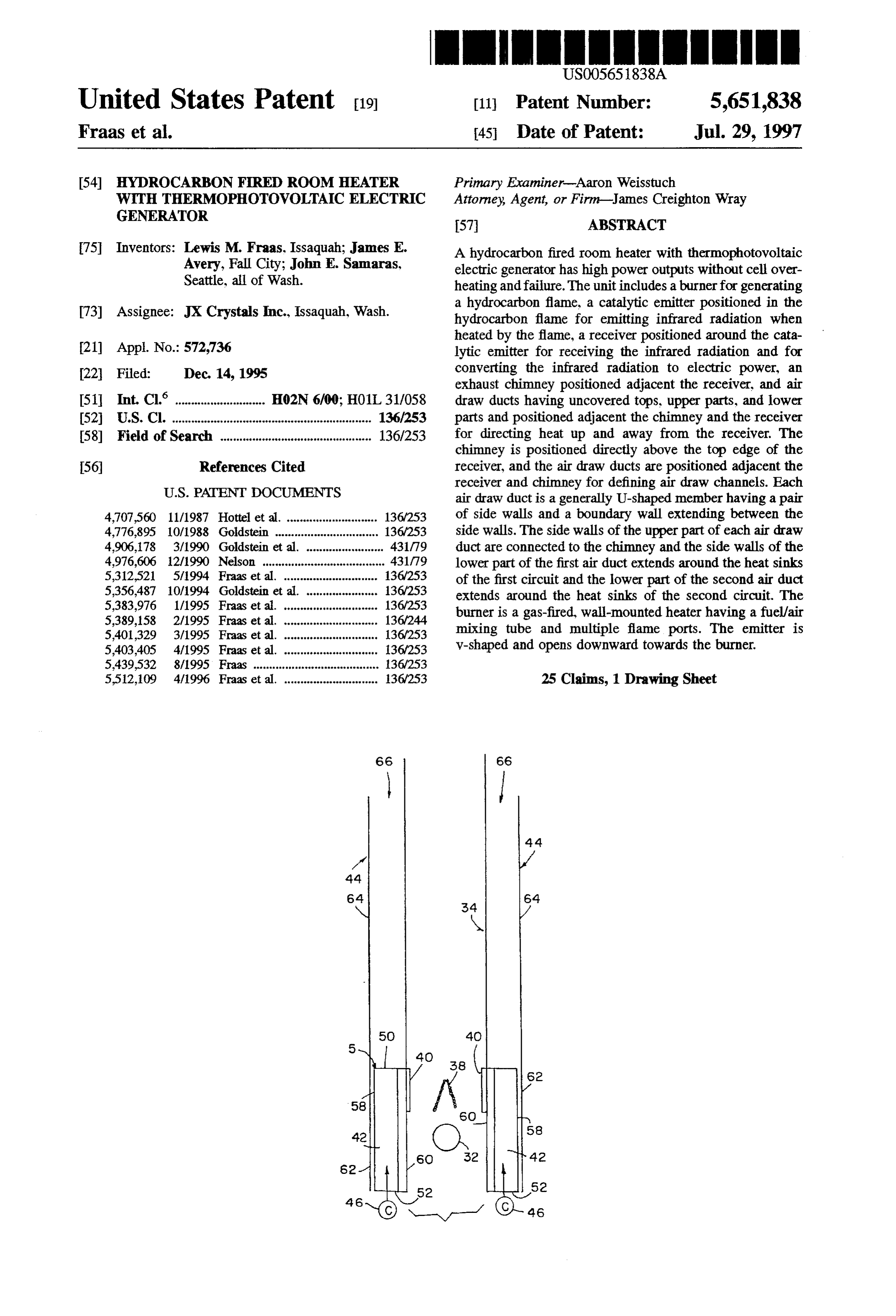
75 Inventors: Lewis M. Fraas, Issaquah; James E. A hydrocarbon fired room heater with thermophotovoltaic Avery, Fall City; John E. Samaras, electric generator has high power outputs without cell over Seattle, all of Wash. heating and failure. The unit includes a burner for generating a hydrocarbon flame, a catalytic emitter positioned in the 73 Assignee: JX Crystals Inc., Issaquah, Wash. hydrocarbon flame for emitting infrared radiation when heated by the flame, a receiver positioned around the cata 21 Appl. No.: 572,736 lytic emitter for receiving the infrared radiation and for 22 Filed: Dec. 14, 1995 converting the infrared radiation to electric power, an exhaust chimney positioned adjacent the receiver, and air 51 Int. Cl. ......... HO2N 6/00; HO1L 31/058 draw ducts having uncovered tops, upper parts, and lower 52 U.S. Cl. ................ 136/253 parts and positioned adjacent the chimney and the receiver 58 Field of Search ............................................... 136/253 for directing heat up and away from the receiver. The chimney is positioned directly above the top edge of the 56 References Cited receiver, and the air draw ducts are positioned adjacent the
receiver and chimney for defining air draw channels. Each air draw duct is a generally U-shaped member having a pair 4,707,560 11/1987 Hotel et al. ............................ 136,253 of side walls and a boundary wall extending between the 4,776,895 10/1988 Goldstein ........ ... 136,253 side walls. The side walls of the upper part of each air draw 4,906,178 3/1990 Goldstein et al. ........................ 431/79 duct are connected to the chimney and the side walls of the 4,976,606 12/1990 Nelson ...................................... 431/79 lower part of the first air duct extends around the heat sinks 5,312,521 5/1994 Fraas et al. ...... ... 136/253 of the first circuit and the lower part of the second air duct 5,356,487 10/1994 Goldstein et al. ...................... 136/253 extends around the heat sinks of the second circuit. The 5,383,976 1/1995 Fraas et al. ............................. 136/253 burner is a gas-fired, wall-mounted heater having a fuel/air 5,389,158 2/1995 Fraas et al. ............................. 136/244 mixing tube and multiple flame ports. The emitter is 5,401.329 3/1995 Fraas et al. ............................. 136,253 5,403,405 4/1995 Fraas et al. .. ... 136/253 v-shaped and opens downward towards the burner. 5.439,532 8/1995 Fraas ........... ... 36/253 552,109 4/1996 Fraas et al. ............................. 36/253 25 Claims, 1 Drawing Sheet
Page 2
Drawing sheet — no readable text.
Page 3
HYDROCARBON FRED ROOM HEATER voltaic cell power density in the receiver, which in turn WITH THERMOPHOTOVOLTAC ELECTRIC improves the generator as an economically viable alternative GENERATOR for electrical power generation.
A thermophotovoltaic generator apparatus includes a
BACKGROUND OF THE INVENTION 5 burner for generating a hydrocarbon flame, a catalytic emit ter positioned in the hydrocarbon flame for emitting infrared
This invention relates to thermophotovoltaic power gen radiation when heated by the flame, a receiver positioned erators for converting fuel to electricity using no moving around the catalytic emitter for receiving the infrared radia parts. tion and for converting the infrared radiation to electric In our previously issued patents thermophotovoltaic gen 10 power, and an exhaust chimney positioned adjacent the erators for high efficiency conversion of fuel energy into receiver. The chimney has a top end, a bottom end, an open electrical energy have been described. While useful for some top, and an open bottom.
applications, those generators primarily generate lower In one preferred embodiment, the receiver is a flexible power outputs. Needs exist for generators having higher circuit of thermophotovoltaic cells having a first end, a power outputs. 15 second end, and multiple bending regions positioned Heat removal is a critical concern with thermophotovol between the first end and the second end. The first end is taic generators. In the conversion of infrared radiation to DC connected with the second end to form a continuous receiver electric power, the thermophotovoltaic cells produce sub extending completely around the emitter. The thermopho stantial heat. That heat flows from the cells and into heat tovoltaic cells are preferably GaSb cells, Ge cells, silicon sinks, where the heat is ultimately removed by convective 20 cells, GanAS cells, or GanSbAS cells. The cells have an air cooling. At high power levels, however, that heatremoval inner surface, an outer surface, and heat sinks connected to is inadequate, and overheating results. Needs exist for high the outer surface. The heat sinks are preferably vertically power output generators having improved heat removal finned aluminum extensions. The emitter is preferably a capabilities. conical emitter or a v-shaped ribbon emitter and is either a 25 platinum emitter, a platinum glazed alumina rod emitted, or
SUMMARY OF THE INVENTION a rare earth oxide selective emitter. The burner preferably includes afuel/air mixing tube having at least one flame port
Propane and natural gas fired wall-mounted room heaters and preferably multiple ports for creating a ribbon flame. are included in many homes and buildings for space heating. In one embodiment, the chimney extends around the Needs exist for electrical power generators that are easily 30 receiver such that the heatsinks are surrounded by the lower retrofitted on existing room heaters, that have commercially end of the chimney, and the upper end extends above an attractive power outputs and that are not prone to overheat upper edge of the receiver. Preferably, the generator includes ing or failure. at least one air draw duct having an uncovered top and A hydrocarbon thermophotovoltaic electric generator pro positioned proximate the receiver for directing heat up and vides for high power output, enhanced heat removal and 35 away from the receiver. The air duct has an upper part and space heating. a lower part, with the lower part positioned around the The generator includes a burner, a catalytic emitter, a receiver and the upper part positioned around the chimney. receiver with thermophotovoltaic cells positioned around A channel is formed between the chimney and the air duct the emitter, and an exhaust chimney near the receiver. The that extends upward from a top edge of the receiver. chimney funnels hot exhaust gases away from the emitter In another preferred embodiment of the present invention, and receiver and simultaneously produces additional air the receiver has a top edge and a bottom edge and includes draw at the base of the burner. That additional air draw first and second circuits of thermophotovoltaic cells posi increases electric power generation through the creation of tioned on opposite sides of the emitter. The cells have inner higher temperature burns and increased infrared output. That Surfaces, outer Surfaces and heatsinks connected to the outer air draw also creates more upward cool air currents that pass 45 surfaces. The thermophotovoltaic cells are preferably GaSb on all sides of the receiver, thereby reducing the hot gas heat cells, Ge cells, silicon cells, GanAS cells, or GainSbAs flow to the cells and improving heatsinkefficiency. Receiver cells. The emitter is preferably a v-shaped emitter opening cell heat sinks are positioned in air streams urged upward by downward towards the burner. The emitter has a first section the chimney, further cooling the cells and permitting greater and a second section. The first section faces a first row of power outputs. 50 thermophotovoltaic cells of the receiver and the second Air draw ducts are included in the present invention for section faces a second row of thermophotovoltaic cells of further increasing efficiency and improving heat removal. the receiver. The emitter is preferably a platinum emitter, a The ducts effectively draw cool air in from below the base platinum glazed alumina rod emitter, or a rare earth oxide of the generator and return heated air to the room. The ducts selective emitter. The burner is a ribbon burner having a are positioned around the receiver and extend upward out 55 fuel/air mixing tube with multiple flame ports. The heat side the walls of the chimney. Air channels are created sinks are preferably finned aluminum extensions. The chim between the walls of the chimney and the ducts. Heat from ney is positioned directly above the top edge of the receiver. the thermophotovoltaic cells of the receiver passes through In preferred embodiments.at least one air draw duct the cooling fins which extends into the air draw ducts. The having an uncovered top is positioned proximate the heat meets a high velocity air flow being pulled upward receiver for directing heat up and away from the receiver. through the ducts from below the burner. The heated air rises The chimney is positioned directly above the top edge of the via natural convection and is further heated by contact with receiver. Each duct has an upper part and a lower part, with the exhaust chimney wall. The heated air exits the open top the lower part of each duct positioned adjacent the outer of the duct and heats the room. surface of the receiver and the upper part positioned adjacent The high velocity airflows drawn in through the bottoms 65 the chimney. A channel is defined between the chimney and of the ducts greatly increase cell cooling efficiency. That the air draw duct and extends upward from the top edge of increased efficiency allows for an increase in thermophoto the receiver.
Page 4
Each air draw duct is preferably a generally U-shaped Experimentation with a Bunsen burner generator unit has member having a pair of side walls and a boundary wall shown that the unit can produce up to 2 Watts of electric extending between the side walls. The side walls of the power. Unfortunately, the cells 6 overheat at high power upper part of each air duct is connected to the chimney and levels. However, that overheating problem is avoided by the side walls of the lower part extend adjacent opposite side adding a chimney 10 to the unit. A unit operated with a edges of the receiver. chimney 10 produces 4 Watts, with the cells 6 actually In a preferred embodiment of the present invention, the running cooler than the 2 Watt unit without a chimney. burner is a gas-fired, wall-mounted heater and the chimney As shown in FIG. 1B, the receiver 5 can be a flexible is a wall-mounted exhaust chimney. First and second air circuit of thermophotovoltaic cells 6 having a first end 11, a draw ducts having uncovered tops, upper parts, and lower 10 second end 13 and multiple bending regions 15 positioned parts are positioned adjacent the chimney and receiver. The between the first end 11 and the second end 13. The first end lower part of each duct is positioned adjacent the outer 11 is connected with the second end 13 to form a continuous surface of the receiver and the upper part is positioned receiver extending completely around the emitter. The adjacent the chimney, thereby defining channels between the receiver 5 has an inner surface 17, an outer surface 19 and chimney and the air draw ducts that extend upward from the 15 heat sinks 21 connected to the outer surface 19. The heat top edge of the receiver. sinks are preferably finned aluminum extensions. As shown A method of electricity generation includes the steps of in FIGS. 1A and 1B, the chimney 10 extends around the suspending a catalytic emitter above aflame port of a burner, receiver 5 such that the heat sinks 21 are encased by the positioning a receiver around the emitter, positioning a 20 lower end 23 of the chimney and the upper end 25 extends chimney above the receiver, producing a flame by combin above an upper edge of the receiver 5.
ing hydrocarbon fuel and air in the burner, heating the The dramatic chimney effect is explained as follows. The emitter to produce infrared energy, collecting the infrared hot exhaust gases in the chimney 10 produce additional air energy in the receiver, removing heat through cooling fins draw at the base of the burner. Additional air enters the extending from the receiver, converting the infrared energy 25 regions A, B, and C. The additional air drawn in with the fuel to DC electric power, and pulling exhaust gases generated by at region A allows for a higher temperature burn, which in the heating step and air from beneath the burner up through turn produces more infrared and thence more electric power the chimney. The pulling step further includes the steps of from the cells. The additional cold air drawn in through drawing air upward through the burner, lifting hot exhaust region B lifts the hot exhaust gas plume away from contact gases away from the receiver, and increasing velocities of air with the cells, thereby reducing the hot gas heat flow to the flows past the cooling fins. Air ducts are preferably posi 30 cells. Finally, the hot gases in the chimney 10 create a higher tioned adjacent the chimney and the receiver for facilitating convection cooling loop which increases the velocity of the heat removal from the cooling fins. airflow past the fins in region C, thereby improving the fin These and further and other objects and features of the cooling efficiency.
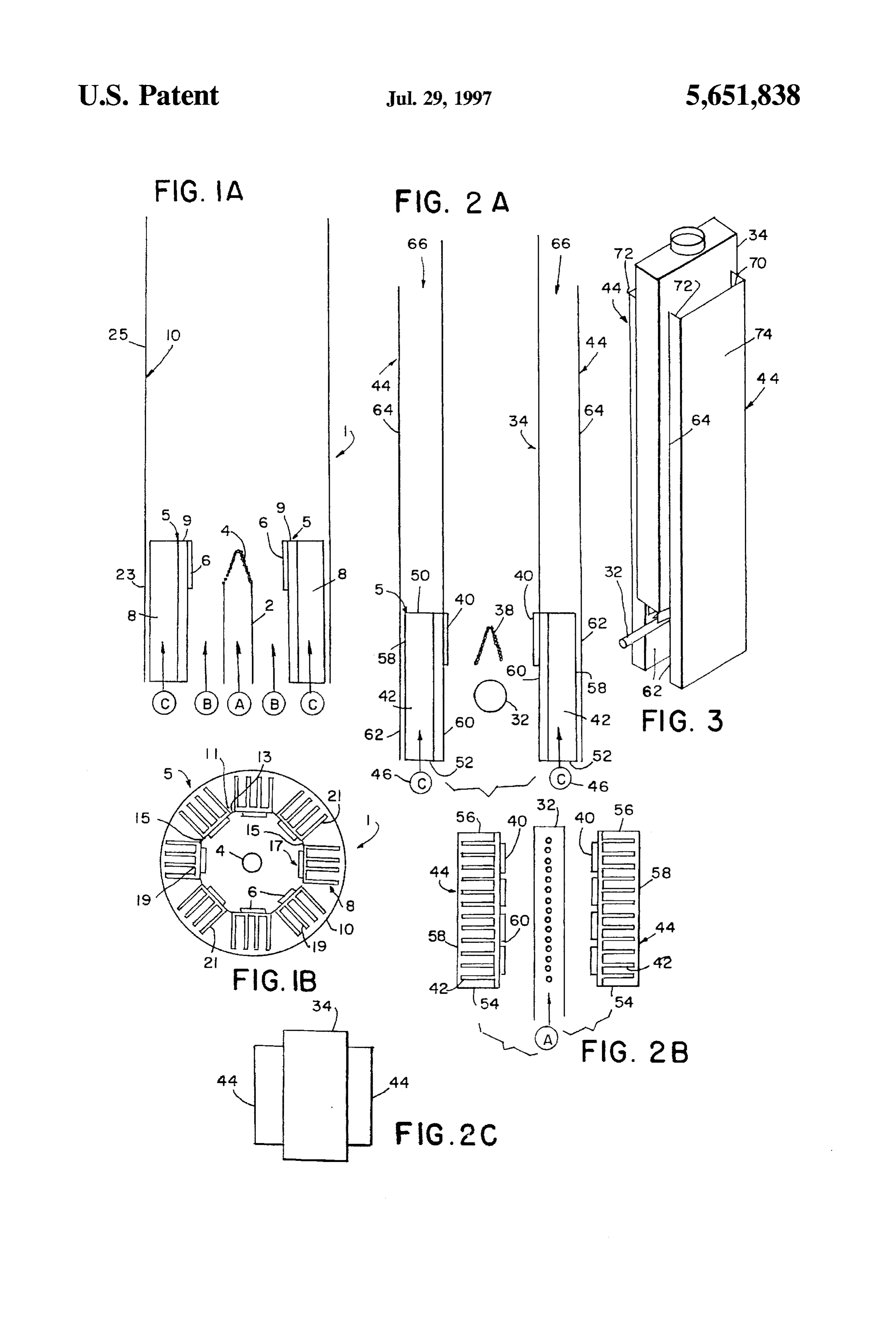
invention are apparent in the disclosure, which includes the 35 FIGS. 2A, 2B, and 2C and FIG. 3 shows a simple above and ongoing written specification, with the claims and commercial thermophotovoltaic power generator 1 devel the drawings. oped by adding a thermophotovoltaic generator to the base BRIEF DESCRIPTION OF THE DRAWTNGS of a propane or natural gas fired wall-mounted room heater. FIG. 1A is a schematic elevation cross-section of a
That unit is commercially attractive, as it can produce both thermophotovoltaic generator having a chimney. heat and electricity. The unit is capable of producing large amounts of electricity while avoiding cell overheating.
FIG. 1B is a plan view of a thermophotovoltaic generator Referring to FIGS. 2A, 2B, and 2C, a simple wall having a chimney. mounted room heater includes a fuel/air supply tube 32 and FIG. 2A is a schematic elevation cross-section of a room a wall-mounted exhaust chimney 34. A row of holes 36 in heater and thermophotovoltaic generator with a chimney and 45 the top of the supply tube 32 creates a ribbon flame. The air draw ducts for cell cooling and room heating. exhaust gases heat the walls of the chimney 34, and the FIG. 2B is a partial schematic plan view of the burner chimney walls in turn heat the air in the room. To add a cells, cooling fins, and air draw ducts. thermophotovoltaic generator to the heater unit, an infrared FIG. 2C is a plan view showing a relationship of a emitter 38 is mounted in the ribbon flame, and circuits of chimney and air draw ducts for cell cooling and room 50 cells 40 are located on either side of the emitter 38. Fins 42 heating. behind the cells 40 transfer waste heat to the room air via FIG. 3 is a perspective view of the room heater and greatly convection. Air draw ducts 44 are added to the unit for thermophotovoltaic generator having air ducts for cell increasing the cell cooling efficiency. That increased cooling, as shown in FIG. 2A. efficiency, which is up to ten fold, leads to major increases 55 in thermophotovoltaic cell power density, which in turn
DETALED DESCRIPTION OF THE dramatically increases the economic viability of such a PREFERRED EMBODIMENTS thermophotovoltaic unit.
Referring to the figures, FIGS. 1A and 1B schematically The air draw ducts 44 work as follows. Without the ducts show athermophotovoltaic electric generator 1 in which fuel 44, heat from the cells 40 passes into the fins 42 and heats and air are supplied through a fuel/air mixing tube 2. An the air around the fins. The less dense heated air then rises infrared emitter 4 is heated by the combustion of the mixed via natural convection. The velocity of the airflow past the fuel and air gases. Infrared radiation from the emitter 4 is fins 42 is a balance between the viscous forces impeding the absorbed by a receiver 5 including thermophotovoltaic cells air flow and the buoyancy force lifting the hot air. Both of 6 and is converted to DC electric power. Waste heat from the these forces are proportional to the height of the fin cells is removed by convective air flow past cooling fins 8. 65 assembly, which is normally six inches. With the ducts 44 in A layer 9 is positioned between the cells 6 and the cooling place, heat from the cells 40 passes into the fins 42 and heats fins 8. the air around the fins 42. The less dense heated air then rises
Page 5
S 6 via natural convection. The heated air then continues to rise the at least one duct being positioned proximate the chimney in the duct 44, being further heated by contact with the and wherein the finned extensions of the heat sinks on the exhaust chimney wall. The viscous force impeding airflow cells of the receiver extend into the at least one duct for is still controlled by the fin height, but the buoyancy force directing heat up and away from the receiver. is now much larger, being proportional to the chimney 6. The apparatus of claim 5, wherein the at least one air height, which can be as much as five feet. The velocity of the duct further comprises an upper part and a lower part, and cooling air entering at the base 46 of the cooling fins 44 at wherein the lower part is positioned around the receiver and region C is then as much as ten times higher, potentially the upper part is positioned around the chimney such that a allowing for the removal of ten times more heat. channel is formed between the chimney and the at least one 10 air duct and extending upward from a top of the receiver.
The air draw ducts 44 are opened at their tops and 7. The apparatus of claim 2, wherein the burner further bottoms. The open tops and bottoms serve to draw cool air comprises a fuel/air mixing tube having plural flame ports in from near the floor and then return heated air to the room. for producing a ribbon flame, and wherein the emitter As shown in FIGS. 2A and 2B, the receiver 5 has a top comprises an elongated emitter.
edge 50, a bottom edge 52, side edges 54, 56, an outer 15 8. The apparatus of claim 2, wherein the receiver further surface 58, and an inner surface 60. The chimney 34 is comprises thermophotovoltaic cells selected from the group positioned directly above the top edge 50 of the receiver 5. consisting of GaSb cells, Ge cells, silicon cells, GanAs The ducts each have a lower part 62 and an upper part 64. cells, and GainSbAs cells.
The lower part 62 of each duct is positioned adjacent the 9. The apparatus of claim 2, wherein the emitter is selected from the group consisting of a platinum emitter, a outer surface 58 of the receiver 5 and the upper part 64 is platinum positioned adjacent the chimney 34, thereby defining a selective glazed emitter.
alumina rod emitter, and a rare earth oxide channel 66 between the chimney 34 and the adjacent air draw duct 44 that extends upward from the top edge 50 of comprises 10. The apparatus of claim 1, wherein the burner further the receiver 5. The heat sink fins extend into the air draw a fuel/air mixing tube having plural flame ports ducts. for producing aribbon flame, wherein the emitter comprises 25 an elongated emitter, wherein the receiver further comprises
As shown in FIG. 3, each air draw duct 44 is preferably first agenerally U-shaped member having a pair of side walls 70, tionedandonsecond circuits of thermophotovoltaic cells posi 72 and a boundary wall 74 extending between the side walls has a top edge and asides opposite of the emitter, wherein the receiver bottom edge, and wherein the chimney 70,72. The side walls 70, 72 of the upper part 64 of each air is positioned above the top edge of the receiver, and further draw duct 44 are connected to the chimney 34 and the side 30 comprising at least one air draw duct having an uncovered walls 70, 72 of the lower part 62 extend adjacent opposite top and positioned proximate the receiver for directing heat side edges of the receiver 5. up and away from the receiver.
Any thermophotovoltaic cell may be used in the present 11. The apparatus of claim 10, wherein the at least one invention, including but not limited to GaSb, Ge, Si, duct has an upper part and a lower part, wherein heat sinks GanAs, and GainSbAs cells. Similarly, any infrared emitter 35 positioned on the receiver extend into the at least one duct, may be used, including but not limited to Pt, Pt glazed and wherein the lower part of the at least one duct is alumina rods and rare earth oxide selective emitters. positioned adjacent the outer surface of the receiver and the While the invention has been described with reference to upper part is positioned adjacent the chimney, thereby specific embodiments, modifications and variations of the defining a channel between the chimney and the at least one invention may be constructed without departing from the air duct that extends upward from the top edge of the scope of the invention, which is defined in the following receiver.
claims. 12. The apparatus of claim 11, wherein the at least one air We claim: ductfurther comprises a generally U-shaped member having 1. Athermophotovoltaic generator apparatus comprising a a pair of side walls and a boundary wall extending between hydrocarbon burner for generating a flame, an emitter posi 45 the side walls, and wherein the side walls of the upper part tioned with respect to the hydrocarbon flame for emitting of the at least one air duct are connected to the chimney and infrared radiation when heated by the flame, a receiver the side walls of the lower part extend adjacent opposite side spaced from the emitter for receiving the infrared radiation edges of the receiver.
and for converting the infrared radiation to electric power, 13. The apparatus of claim 12, wherein the at least one and an exhaust chimney positioned adjacent the receiver, the 50 duct extends downward to an open bottom below the chimney further comprising an open top and an open bot receiver and the fuel/air mixing tube.
ton 14. The apparatus of claim 12, wherein the chimney is 2. The apparatus of claim 1, wherein the receiver further rectangular in cross-section, wherein the at least one air comprises multiple thermophotovoltaic cells connected in a draw duct comprises a first duct and a second duct mounted circuit, wherein the cells have inner surfaces and outer 55 on opposite sides of the chimney, wherein the heat sinks Surfaces and further comprising heat sinks connected to the extend into the ducts, and wherein the lower part of the first outer surfaces of the cells wherein the heat sinks further air duct extends around the heat sinks of a first row of cells comprise finned extensions. and the lower part of the second air duct extends around the 3. The apparatus of claim 2, wherein the chimney extends heat sinks of a second row of cells. around the heat sinks' finned extensions. 15. The apparatus of claim 14, wherein the receiver 4. The apparatus of claim3, wherein the chimney extends further comprises thermophotovoltaic cells selected from around the receiver such that the heat sinks finned exten the group consisting of GaSb cells. Ge cells, silicon cells, sions are positioned in a lower end of the chimney and an GanAs cells, and GainSbAs cells. upper end of the chimney extends substantially above the 16. The apparatus of claim 14, wherein the emitter is receiver. 65 selected from the group consisting of a platinum emitter, a 5. The apparatus of claim 2, further comprising at least platinum glazed alumina rod emitter, and a rare earth oxide one air draw duct having an open top and an open bottom, selective emitter.
Page 6
17. The apparatus of claim 1, wherein the burner is a walls of the lower parts of the air ducts extend around the heater. heat sinks of the cells and the lower parts of the air ducts 18. The apparatus of claim 17, wherein the heater is a extend downward beneath the burner.
gas-fired, wall-mounted heater. 22. The apparatus of claim 21, wherein the burner is a 19. The apparatus of claim 18, wherein the chimney is a gas-fired, wall-mounted heater further comprising a fuel/air wall-mounted exhaust chimney. mixing tubehaving multiple flame ports, wherein the emitter 20. The apparatus of claim 19, further comprising first and is an inverted V-shaped elongated emitter opening down second air draw ducts having upper parts and lower parts ward towards the burner, the emitter having a first section with openings at tops and bottoms thereof, and wherein the and a second section, and wherein the first section faces a receiver has heat sinks extending outward therefrom, 10 first row of thermophotovoltaic cells of the receiver and the wherein the chimney is positioned above the receiver, and second section faces a second row of thermophotovoltaic wherein the lower parts of the ducts are positioned adjacent cells of the receiver.
the outer surface of the receiver heat sinks and the upper 23. Athermophotovoltaic generation method, comprising parts are positioned adjacent the chimney, thereby defining the steps of suspending an emitter above a flame port of a channels between the chimney and the air draw ducts that 15 burner, positioning a receiver around the emitter, positioning extend upward along the chimney. a chimney having an open top and an open bottom above the 21. Aheater and thermophotovoltaic generator apparatus, receiver, producing a flame by combining hydrocarbon fuel comprising a burner for generating a flame, an emitter and air in the burner, heating the emitter and producing positioned near the flame for emitting infrared radiation infrared energy, collecting the infrared energy in the when heated by the flame, a receiver positioned around the 20 receiver, removing heat through heat sink cooling fins emitter for receiving the infrared radiation and for convert extending from the receiver, converting the infrared energy ing the infrared radiation to electric power, an exhaust to DC electric power, and drawing exhaust gases generated chimney positioned adjacent the receiver, and air draw ducts by the heating step and air from beneath the burner up having upper parts and lower parts and positioned adjacent through the chimney and over the heat sinkfins for cooling the chimney and the receiverfor directing heat up and away 25 the receiver.
from the receiver and away from the chimney, the chimney 24. The method of claim 23, wherein the drawing step further comprising an open top and an open bottom, the further comprises the steps of drawing air upward through receiver further comprising first and second circuits of the burner, lifting hot exhaust gases away from the receiver, thermophotovoltaic cells positioned on opposite sides of the and increasing velocities of air flows past the cooling fins. emitter, wherein the cells have outer surfaces and heat sinks 30 25. The method of claim 23, further comprising the steps connected to the outer surfaces, wherein the chimney is of positioning air ducts adjacent the chimney and the positioned above the receiver cells, wherein each air draw receiver, positioning the heat sink fins in the air ducts and ductfurther comprises a generally U-shaped member having heating air in the air ducts with heat removed from the a pair of side walls and an outer wall extending between the cooling fins and from the chimney. side walls, and wherein the side walls of the upper part of 35 each air draw duct are connected to the chimney and the side :k :: :: *k sk
Provenance
- Collection
- Cited prior art
- Original PDF
- patentimages.storage.googleapis.com →
- Filed
- 1995-12-14
- Pages
- 6
- Method
- pdftotext (the PDF's own text layer) + pdftoppm 300dpi page scans
- Source
- Google Patents bibliographic record
- Granted
- 1997-07-29
- Inventors
- Lewis M. Fraas; James E. Avery; John E. Samaras; JX Crystals Inc
- Transcribed from
- patentimages.storage.googleapis.com →