patent · US4136016
Hydrocarbon conversion process utilizing a magnetic field in a fluidized bed of catalitic particles
23 January 1979
Page 1 — bibliographic record
United States Patent (19) 11) 4,136,016 Rosensweig 45) Jan. 23, 1979 54 HYDROCARBON CONVERSION PROCESS Heterogeneity of a Fluidized Bed of Catalyst for the UTLZNGA MAGNETC FELD INA Synthesis of Ammonia in an Electromagnetic Field. FLUDZED BED OF CATALTC D. G. Ivanov et al., Kinetika: Katalizvol. 11, No. 5, pp. PARTICLES 1214-1219 (1970) Ammonia Synthesis on a Catalyst 75 Inventor: Ronald E. Rosensweig, Summit, N.J. Fluidized in a Magnetic Field. Primary Examiner-George Crasanakis 73 Assignee: Exxon Research & Engineering Co., Attorney, Agent, or Firm-Albert P. Halluin Forham Park, N.J.
(21) Appl. No.: 866,780 A hydrocarbon conversion process, such as catalytic (22 Filed: Jan. 3, 1978 desulfurization of a vaporized petroleum feedstock with hydrogen or catalytic reforming of a vaporized hydro
Related U.S. Application Data carbon feedstock, is carried out by passing the gaseous medium upwardly through a fluidized bed of magnetiz 60) Division of Ser. No. 786,613, Apr. 11, 1977, Pat. No. able composite particles having catalytic activity for 4,115,927, which is a continuation-in-part of Ser. No. hydrocarbon conversion and which contain 2 to 40 610,071, Sep. 3, 1975, abandoned, which is a volume 9% ferro- or ferrimagnetic material to a nontime continuation-in-part of Ser. No. 514,003, Oct. 11, 1974, abandoned. varying (direct current) and substantially uniform ap plied magnetic field having a substantial component (51) Int. Cl?....................... C10G 23/10; C10G 35/14 along the direction of gravity such that the composite 52 U.S. C. ..................................... 208/134; 208/213 particles have a component of magnetization along the 58) Field of Search ............... 208/213, 134,209, 177, direction of gravity. The gaseous medium is also the 208/133, 46, 108 fluidizing medium passing upwardly at a superficial gas 56) References Cited velocity ranging between: (l) at least twice the normal minimum superficial gas
Re.25,770 4/1965 Johanson ............................. 208/213 of said applied magnetic field, and 2,614,064 10/1952 Carney ........ ... 208/177 (2) less than the superficial gas velocity required to 2.987,468 6/1961 Chervenak .. ... 208/23 cause time-varying fluctuations of pressure differ 3,440,731 4/1969 Tuthill ..................................... 34/ ence through said bed for a 0.1 to 1 second time OTHER PUBLICATIONS interval during continuous fluidization in the pres ence of said applied magnetic field.
D. G. Ivanov et al., International Chemical Engineering vol. 15, No. 3, pp. 557-560, (1975) Investigation of the 6 Claims, 7 Drawing Figures
STABLE FLUDIZEDEMULSION
BUBBLE
FIELD
COIL
FLOW INPU FLOW INPUT
Page 2
Drawing sheet — no readable text.
Page 3
Drawing sheet — no readable text.
Page 4
Drawing sheet — no readable text.
Page 5
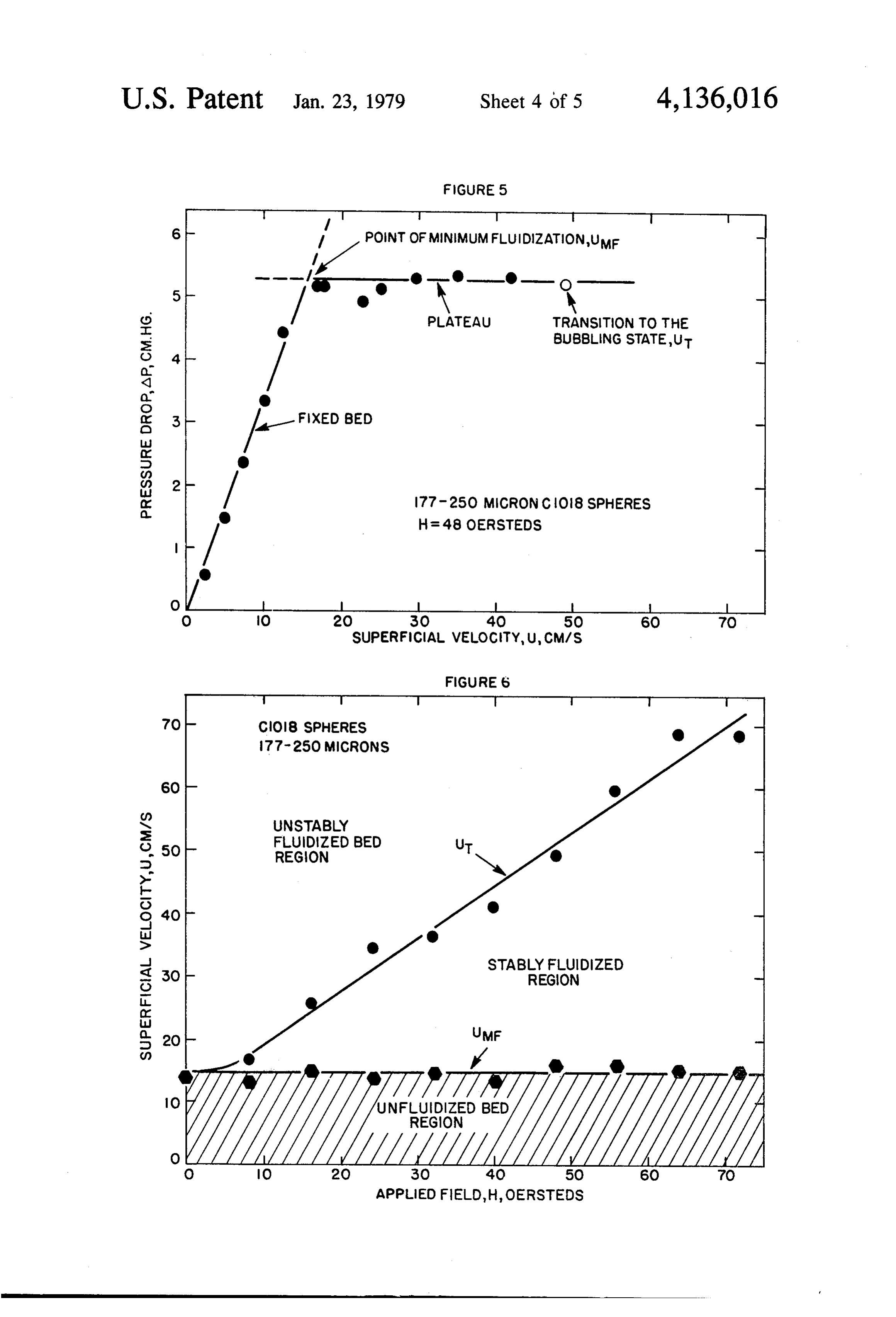
FIGURE 5
/ POINT OF MINIMUM FLUIDIZATION,UM
- , as O • '-- M PLATEAU TRANSiTION TO THE
BUBBLING STATE, UT
77 - 25 O MCRON CO8 SPHERES
H = 48 OERSTEDS
O O 2O 3O 4O 5O 6O 7O
SUPERFICIAL VELOCITY, U, CM/S
FIGURES
REGON
BED
- STABLY FLUIDZED S 3O REGON
APPLIED FELD, H, OERSTEDS
Page 6
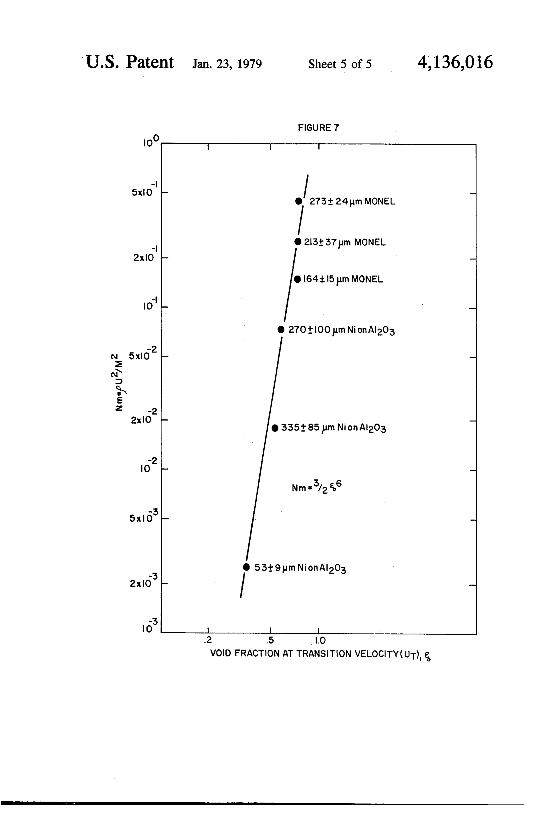
FIGURE 7
o 164:15pm MONEL
O 270tloom Nion Al2O3 O 335it 85um Nion Al2O3 53t 9pm Nion Al2O3
VOID FRACTION AT TRANSiTION VELOCITY(UT),
Page 7
rameters including particle size, particle density, etc.
HYDROCARBON CONVERSION PROCESS Any increase in the fluid flow beyond the incipient UTILIZNGA MAGNETC FELD INA fluidization point causes an expansion of the fluidized FLUIDZED BED OF CATALTC PARTICLES bed to accommodate the increased fluid flow until the CROSS REFERENCE TO RELATED gas velocity exceeds the free falling velocity of the APPLICATION particles which are then carried out of the apparatus, a condition otherwise known as entrainment.
This application is a division of application Ser. No. Fluidized beds possess many desirable attributes, for 786,613, filed Apr. 11, 1977, now U.S. Patent No. example, in temperature control, heat transfer, catalytic 4,115,927, granted Sept. 26, 1978, which in turn is a 10 reactions, and various chemical and physical reactions continuation-in-part of application Ser. No. 610,071, such as oxidation, reduction, drying, polymerization, filed Sept. 3, 1975, and now abandoned, which in turn is coating, diffusion, filtering and the like. a continuation-in-part of application Ser. No. 514,003, Among the problems associated with fluidized beds, a filed Oct. 11, 1974, now abandoned. most basic one is that of bubble formation, frequently 15 resulting in slugging, channeling, spouting, attrition and
FIELD OF THE INVENTION pneumatic transport. This problem is most common in This invention relates to a fluidized bed process. gas-fluidized systems, Bubbling causes both chemical More particularly, the present invention is concerned and mechanical difficulties: for example, in gas-solids with a process for operating a magnetically stabilized reaction gas bubbles may bypass the particles altogether fluidized bed under conditions such that the flow of gas 20 resulting in lowered contacting efficiency while chaotic used to fluidize solid particulate magnetizable and flui motion of the bed solids may set up detrimental me dizable particles and an applied magnetic field are con chanical stresses tending to deteriorate the vessel and its trolled to the extent that there is substantially no time contents. Many procedures and systems have been pro varying fluctuation of pressure at a point taken in the posed to effect improvements, for example, by the use bed. Such a magnetically stabilized medium has the 25 of baffles, gas distribution perforated plates, mechanical appearance of an expanded fixed bed; there is no gross vibration and mixing devices, the use of mixed particle solids circulation and very little or no gas bypassing. A sizes, gas plus liquid flow schemes, special flow control bed of the magnetically stabilized medium shares many valves, etc.
qualities of the normal fluidized bed; pressure drop is for example, U.S. Pat. No. 3,169,835 to Huntley et al effectively equal to the weight of the bed divided by its 30 disclose that mesh packing throughout the bed breaks cross sectional area, and independent of gas flow rate or up large gaseous bubbles and prevents coalescence of of particle size; the medium will flow, permitting con existing bubbles. However, baffle devices do not pre tinuous solids throughput. Beds of the magnetically vent the initiation of bubble formation. stabilized media also share some of the qualities of a fixed bed; countercurrent contacting can be readily 35 DESCRIPTION OF THE PRIOR ART attained; gas bypassing is small or absent, making it In recent years patents have issued which describe possible to achieve high conversions and attrition is means for suppressing bubble formation in a fluidized minimal or absent. bed. For example, U.S. Pat. No. 3,304.249 to Katz dis The simultaneous possession of properties usually closes that a stabilized fluidized bed is obtained when a associated with the media of fixed and of fluid beds is bed containing solids having a moderate surface elec highlighted, for example, in the use of a magnetically troconductivity is fluidized by a gaseous medium hav stabilized medium to trap particulates. Like the medium ing a sufficiently high ionizapotential to provide a co of a fixed bed, it will trap the particulates; like the me rona discharge without arcing and subjecting a high dium of a fluid bed, it will not clog- the pressure drop voltage to a portion of the bed to cause a corona dis of a bed of the medium will increase only by as much as 45 charge in the fluidized bed.
due to the weight of the trapped material. In another patent, U.S. Pat. No. 3,439,899 to BACKGROUND OF THE INVENTION Hershler, there is dislosed a process for producing a fluidized bed free of bubbles bypassing a fluid upwardly
Many chemical and physical processes such as cata through a particulate solid fluidizable material which lytic cracking, hydrogenation, oxidation, reduction, 50 includes a plurality of discrete magnet particles having drying, polymerization, coating, filtering and the like a coercive force exceeding 50 oersteds to impart an are carried out in fluidized beds. A fluidized bed briefly, upward force to the solid particulate fluidizable mate consists of a mass of solid particulate fluidizable mate rial and subjecting the fluidizable material to a magnetic rial in which the individual particles are neutrally levi field varying with time in direction and intensity to tated free of each other by fluid drag forces whereby 55 impart individual motions to the magnet particles. A the mass or fluidized bed possesses the characteristics of similar process is disclosed in U.S. Pat, No. 3,219,318 to a liquid. Like a liquid, it will flow or pour freely, there Hershler. Z. I. Nekrasov and V. V. Chekin, in their is a hydrostatic head pressure, it seeks a constant level, articles appearing in Izy, Akad Nauk, USSR, Otdel, it will permit the immersion of objects and will support Tekh, Nauk, Metallurgiya i Topliyo at 6, 25-29 (1961) relatively buoyant objects, and in many other properties and at 1, 56-59 (1962) disclose that the formation of it acts like a liquid. A fluidized bed is conventionally bubbles and slugs in a fluidized bed may be eliminated produced by effecting a flow of a fluid, usually gas, over a wide range of variation of flow rates by a later through a porous or perforated plate or membrane un ally applied variable magnetic field due to the interac derlying the particulate mass, at a sufficient rate to tion of this field with fluidized ferromagnetic particles. support the individual particles against the force of 65 U.S. Pat. No. 3,440,731 to Tuthill discloses a process gravity. Conditions at the minimum fluid flow required for stabilizing and suppressing bubble formation in a to produce the fluid-like, or fluidized condition, i.e., the fluidized bed, containing particulate solids having ferro incipient fluidization point are dependent on many pa magnetic properties by subjecting the fluidized bed to a
Page 8
magnetic field. While it is disclosed that either an alter ence of an applied uniform, time-steady magnetic field nating current or a direct current electromagnet may be oriented parallel with the direction of fluid flow, a sta used, the only example in the patent describes an alter bly fluidized bed results over a substantial range of gas nating current electromagnet, thus producing a mag velocities. . . . , , , netic field varying with time in direction and intensity. The basis for the phenomenon is believed to relate to Numerous publications by Ivanov and coworkers and the behavior of magnetic stress in the fluidized medium a publication by Sonoliker et al disclose the application which is viewed as a homogeneous magnetized contin of a magnetic field produced from a direct current (non uum. A local perturbation in voidage modifies the uni time varying) electromagnet to fluidize iron or iron form magnetic stress of the unperturbed bed creating chromium particles such as used in ammonia synthesis 10 magnetic forces that tend to restore the medium to the or carbon monoxide conversion. These articles include: uniform state. A general expression for the magnetic Sonoliker et al, Indian Journal of Technology, 10, stress tensor is provided in Ferrohydrodynamics, Entry 377-379 (1972); Ivanov et al Zhurnal Prikladnoi Khimi, in the "Encyclopaedic Dictionary of Physics,” Suppl. 43, 2200-2204 (1970); Ivanov et al., Zhurnal Prikladnoi Vol. 4, by R. E. Rosensweig, Edited by J. Thewlis, Khimi, 45, 248-252 (1972); Ivanov et al, International 15 Pergamon Press (1971).
Chemical Engineering, 15, 557-560 (1975) (also pub lished in Chemical Industry, 11, 856-858 (1975) and The SUMMARY OF THE INVENTION Soviet Chemical Industry, 6, 713-715 (1974); Ivanov et As one embodiment of the present invention there is al, Comptes rendus de l'Academie bulgare des Science, disclosed a process for fluidizing a bed containing solid
Tome 25, No. 8, 1053-1056 (1972); and Ivanov et al. particulate magnetizable, fluidizable material and fluid Comptes rendus de l'Academie bulgare des Science, Tome izing fluid located within an external force field wherein 23, No. 7, 787-790 (1970). In some of the published at least a portion of said bed containing said solid partic work of Ivanov and coworkers a gradient applied mag ulate magnetizable, fluidizable material and fluidizing netic field is used to generate body forces to hold fine particles in place and thus permit higher flow rates than 25 fluid tially are subjected to a nontime varying and substan uniform applied magnetic field having a substan in conventional beds. For example, the work reported tial component along the direction of the external force in British Pat. No. 1,148,513 and Ivanov et al., Kinet, field such that said solid particulate magnetizable, flui Katel 11, No. 5, 1214-19 (1970) varied the direction of dizable material has a component of magnetization the field from transverse to axial in relation the flow.
In general, the published works of Sonoliker etal and 30 along wherein the direction of the external force field and at least a portion of said bed containing the
Ivanov et al, teach that higher gas velocities can be used solid particulate in the presence of an applied magnetic field than in its stably fluidized bymagntizable, fluidizable material is absence. For example, Ivanov et al. state in Zhurnal said external force field at a superficial fluid the flow of fluidizing fluid opposing velocity
Pikkladnoi Khimi, 45,248-252 (1972) at page 251: "Lin ranging between:
ear gas velocities higher by 30-40% can be used under 35 (a) more than the normal fluidization superficial fluid high pressure in the presence of a magnetic field than in velocity required to fluidize said bed in the absence of its absence, at the same degree of bed expansion without said applied magnetic field; and, appreciable breakdown of the bed structure and with (b) less than the superficial gas velocity required to out transport of particles out of the bed.' However, cause time-varying
Sonoliker et all and Ivanov et al provide no recognition through said stably fluctuations fluidized bed of pressure difference portion over a finite of the existence of the stably fluidized non-bubbling bed time period during continuous fluidization in the pres and appear to erroneously interpret the transition from ence the stably fluidized state to the unstably fluidized (bub mum fluidization superficial fluid velocity is the mini of said applied magnetic field. The normal bling) state as the transition from fixed to fluidized velocity observed when the pressure difference offluid the states. Furthermore, they did not teach the essential role 45 fluid passing through the fluidized bed, as measured played by orientation and the significance of role played between the upper and lower surfaces of the bed, is first by uniformity of the applied magnetic field. In a uni substantially the same as the bed weight per unit cross form applied magnetic field, the bed is free of any net sectional area.
magnetic force. The strength of the magnetic field and its minimal Workers at the Brookhaven Laboratories, H. Katz 50 deviation and J. T. Sears, Can. J. Chem. Eng. 47, 50-53 (1969) force fieldfrom a colinear orientation to the external are maintained so as to prevent and/or sup described a process for the stabilization of a fluidized press bed of dielectric particles by use of an electric field. given formation of bubbles in the fluidized media at a fluid flow rate and with a selected fluidized parti
These workers disclose that glass bead and silica gel cles makeup.
particle beds were observed to behave as packed beds at 55 Fluid throughput rates. which . . are up to 10 to 20 or flow rates (and pressure drops) of fluidizing gas up to 15 times the normal incipient fluidization rate. Katz and fluidization in the absence of the appliedbed more times the flow rate of the fluidized at incipient magnetic field
Sears also disclose in the cited article the use of an imposed axial magnetic field (alternating or unidirec are achieved, concomitant with the substantial absence tional) to stabilize a bed of iron particles, but indicate of bubbles. The magnetically stabilized fluidized bed that the iron particles under the influence of a strong grossthesolids has appearance of an expanded fixed bed with no circulation and very little or no gas bypass magnetic field are in the form of a slug. ing.
THE DISCOVERY OF THE PRESENT
BRIEF DESCRIPTION OF THE DRAWINGS
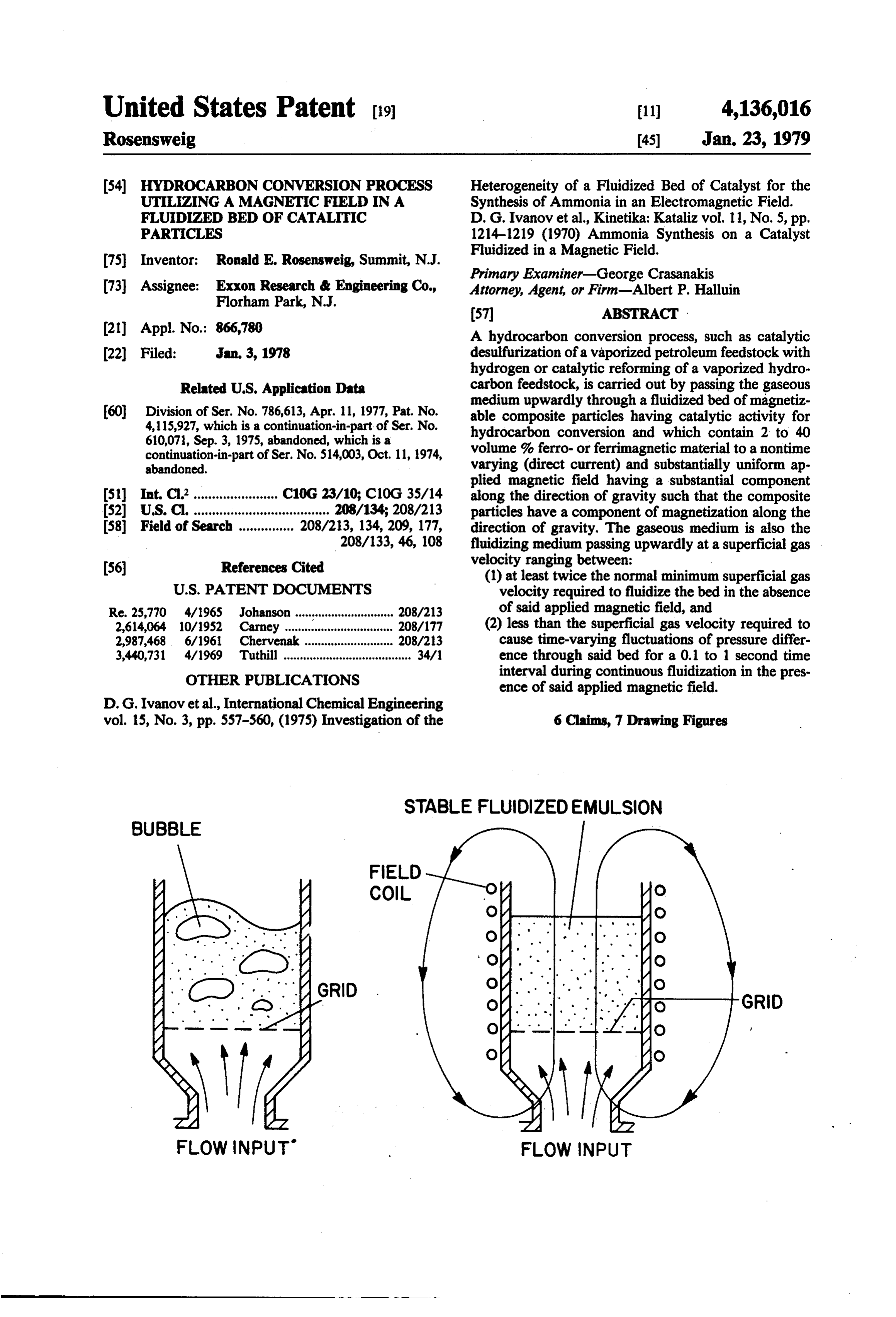
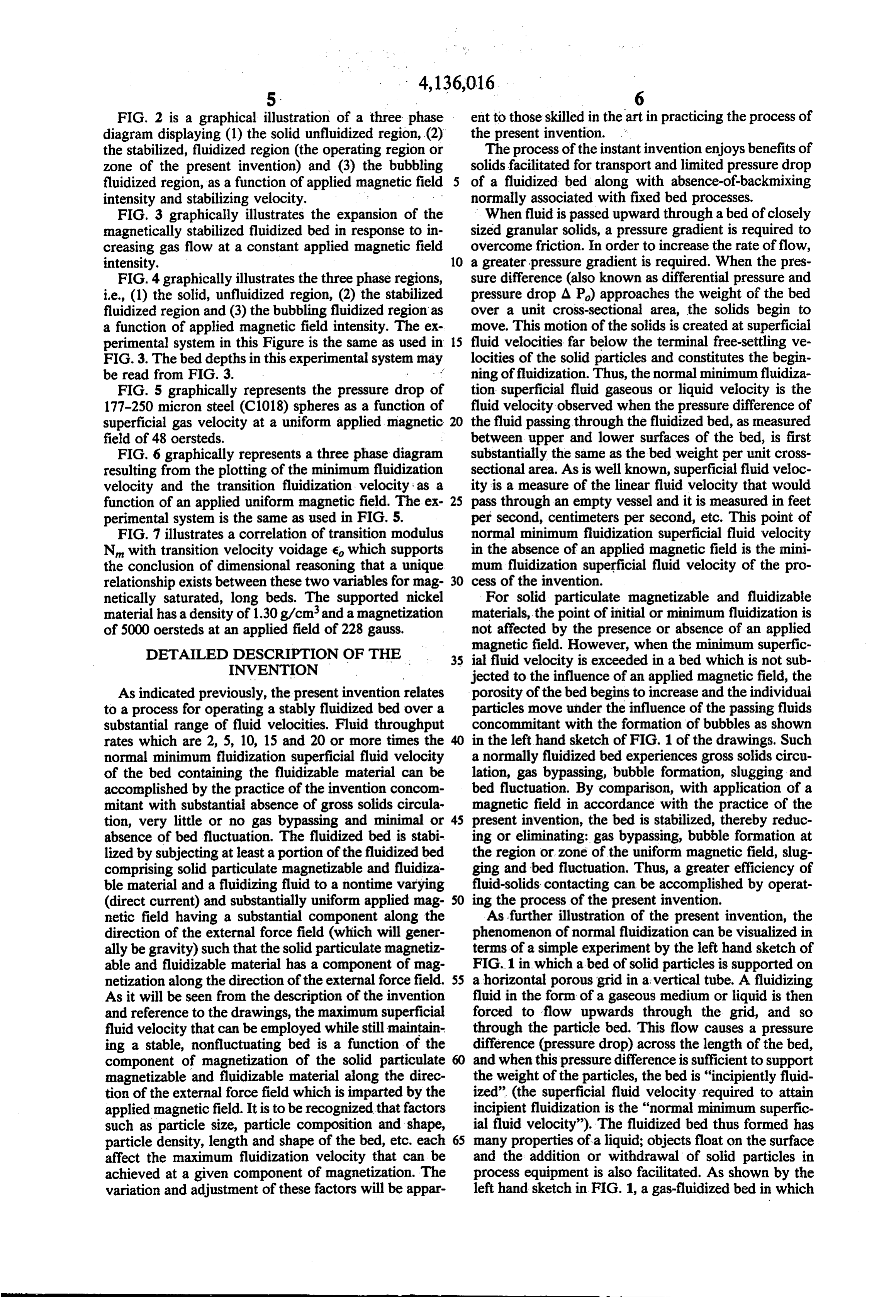
It has been discovered that by fluidizing a bed con FIG. 1 is a schematic representation comparing the taining solid particulate magnetizable and fluidizable magnetically stabilized fluidized bed of the present in material with a fluid such as a gas or liquid in the pres vention with an ordinary unstabilized fluidized bed.
Page 9
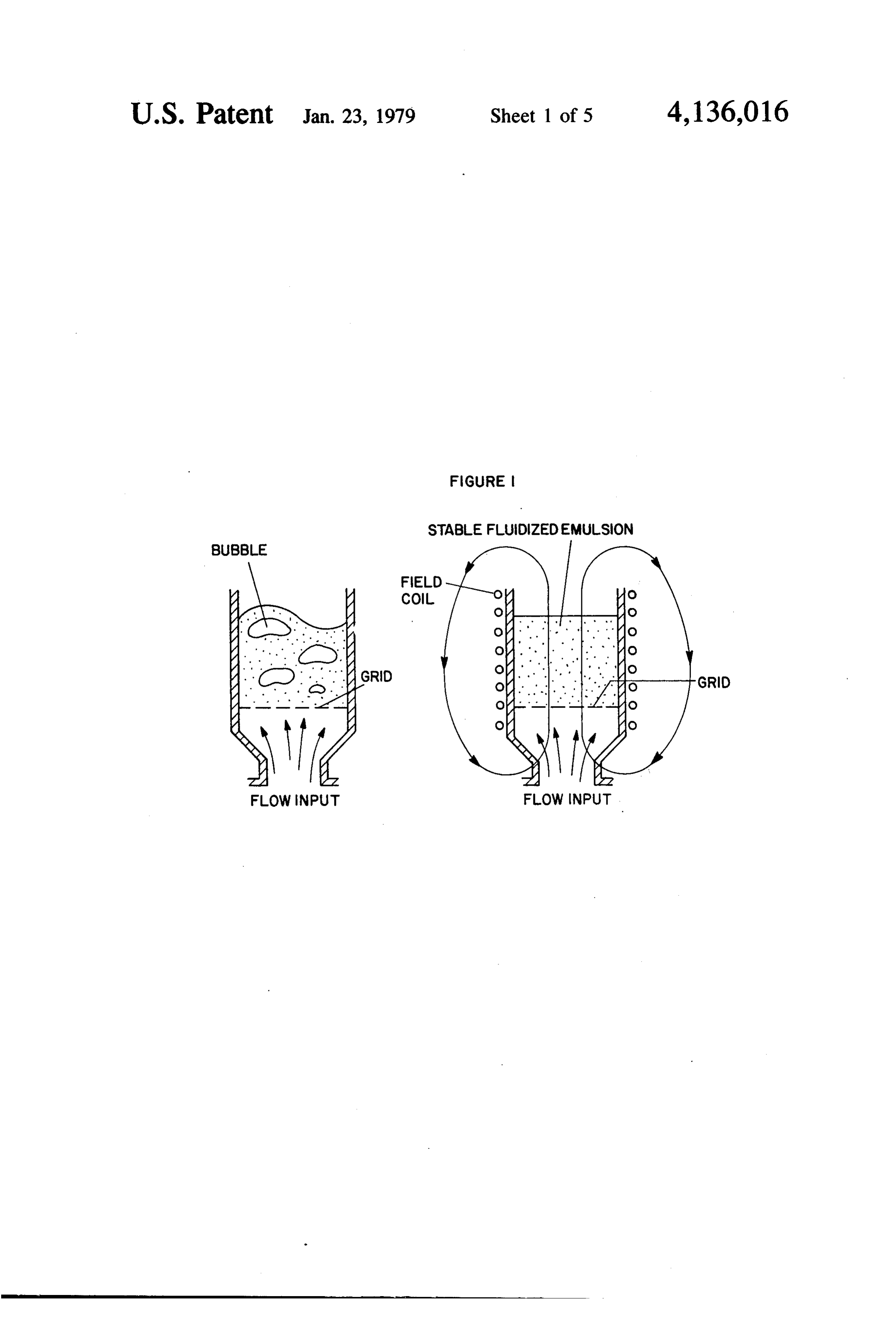
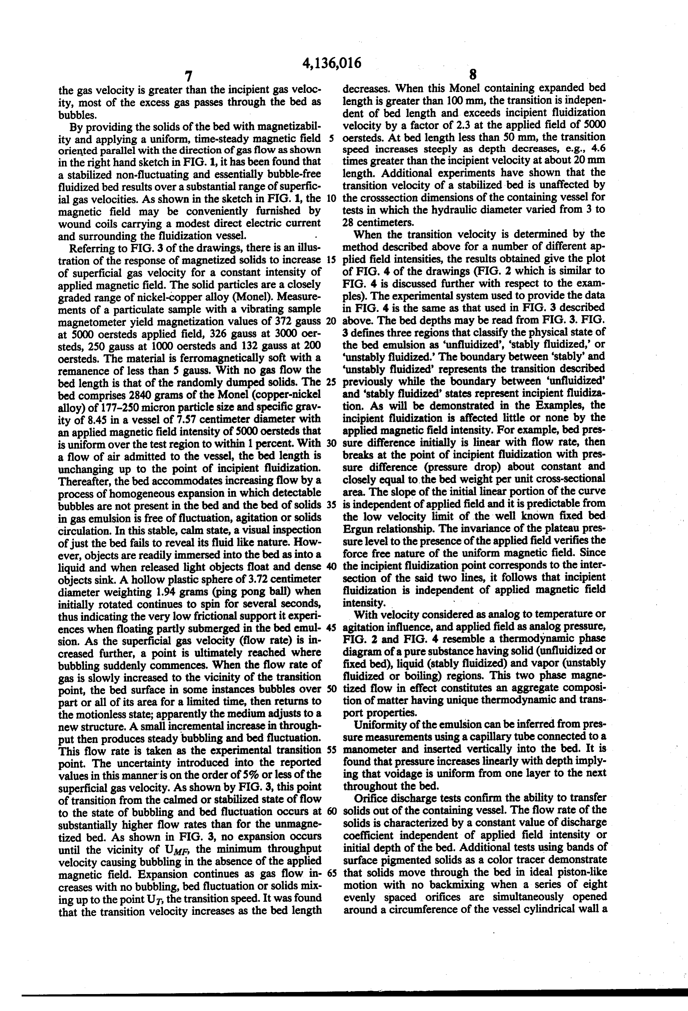
FIG. 2 is a graphical illustration of a three phase ent to those skilled in the artin practicing the process of diagram displaying (1) the solid unfluidized region, (2) the present invention.
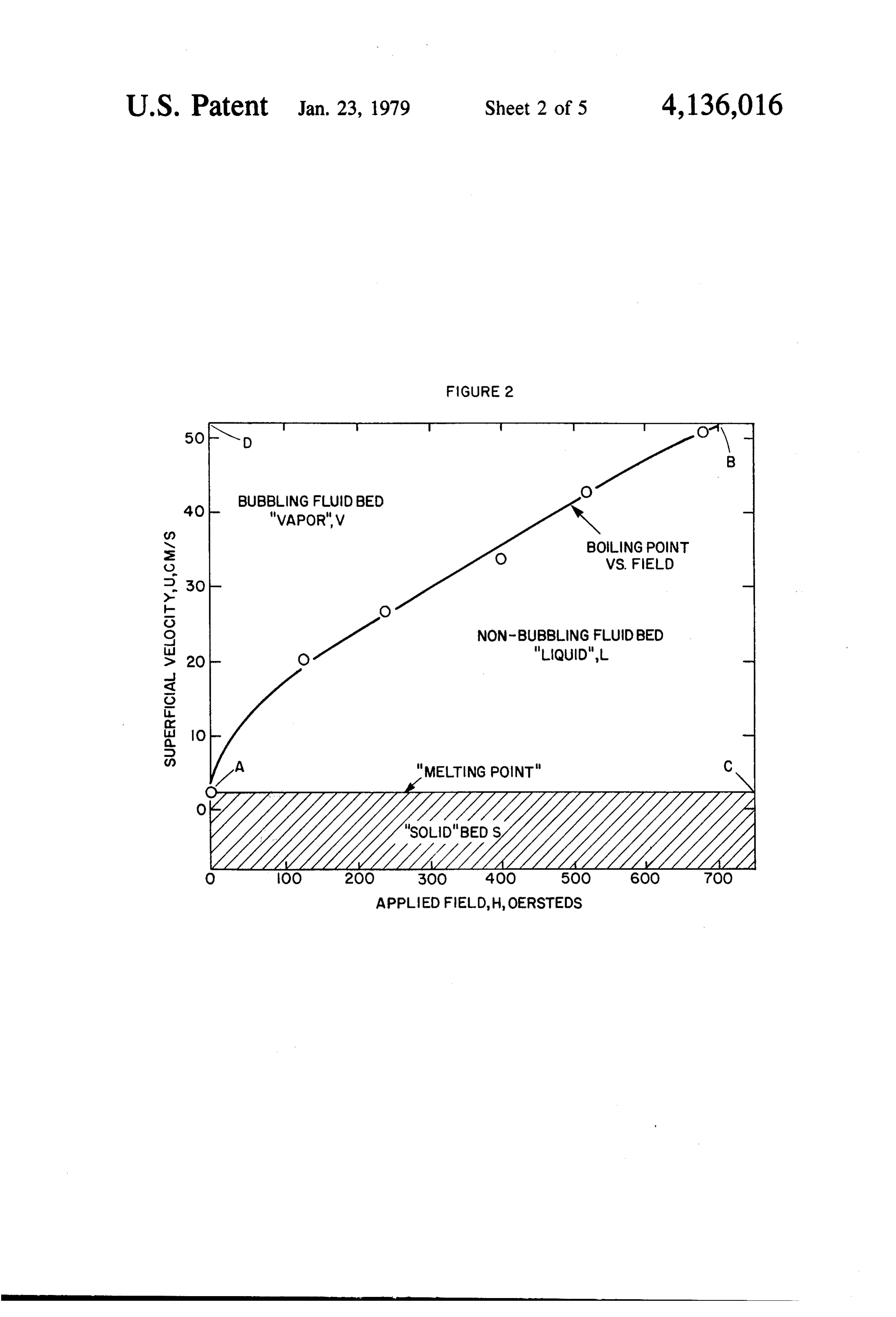
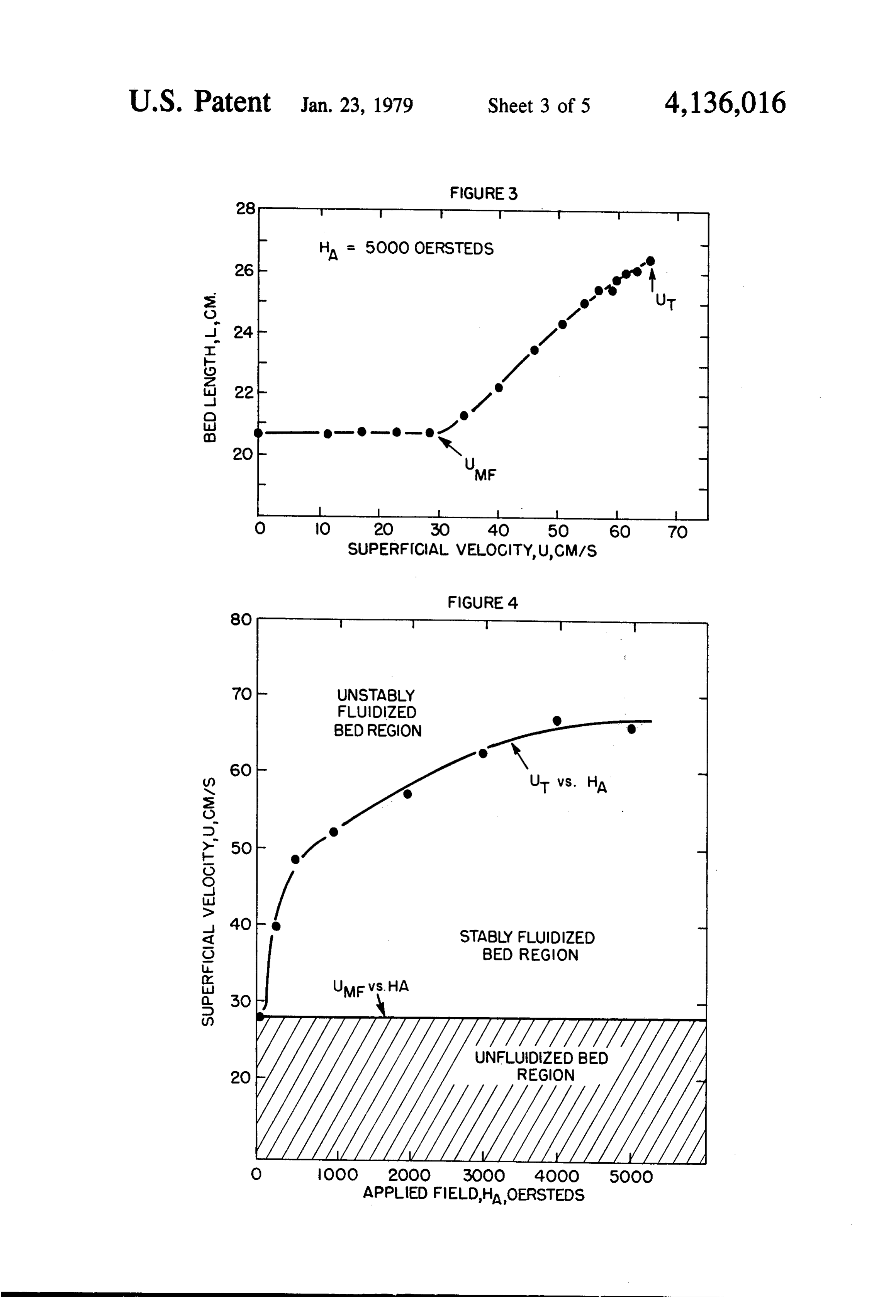
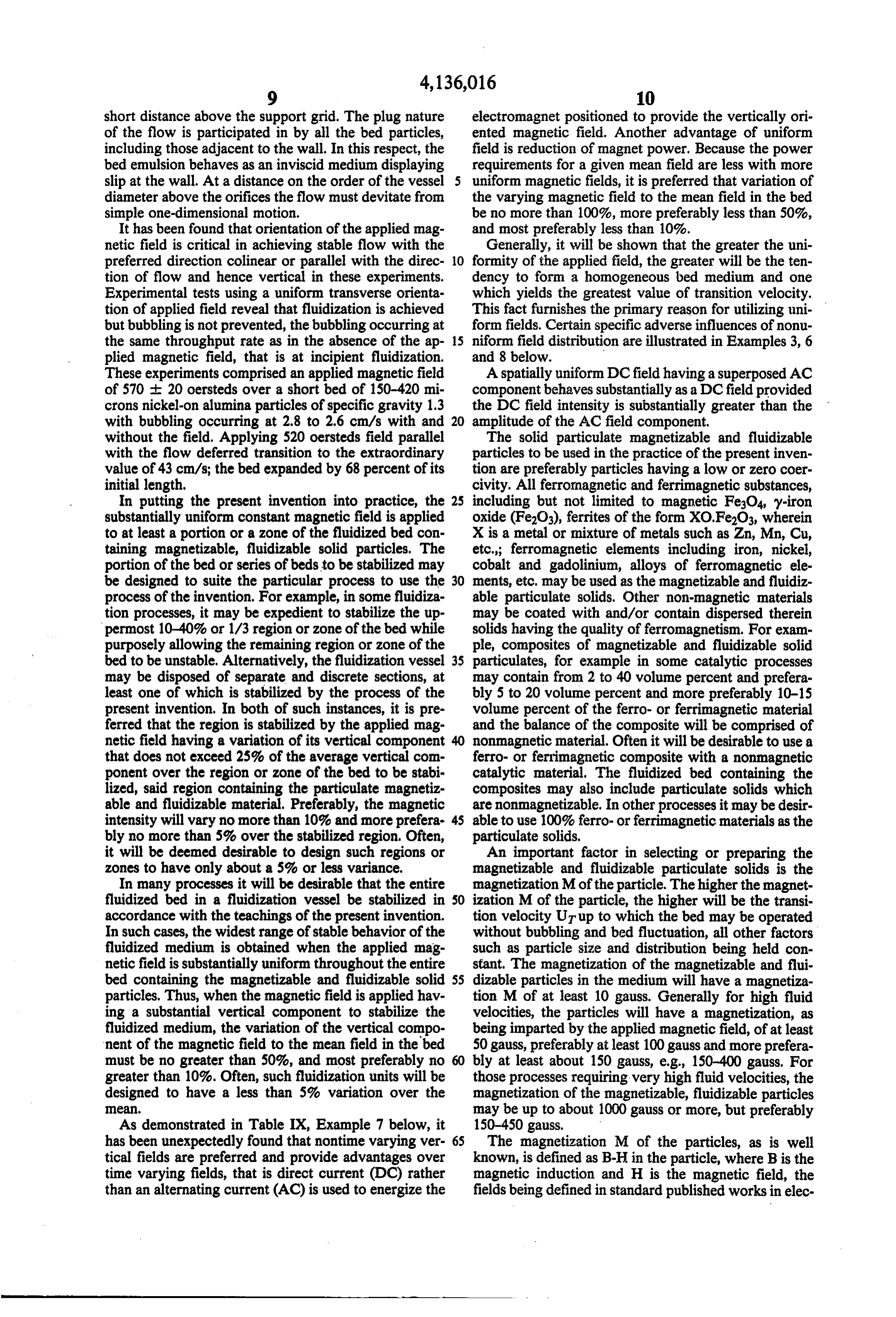
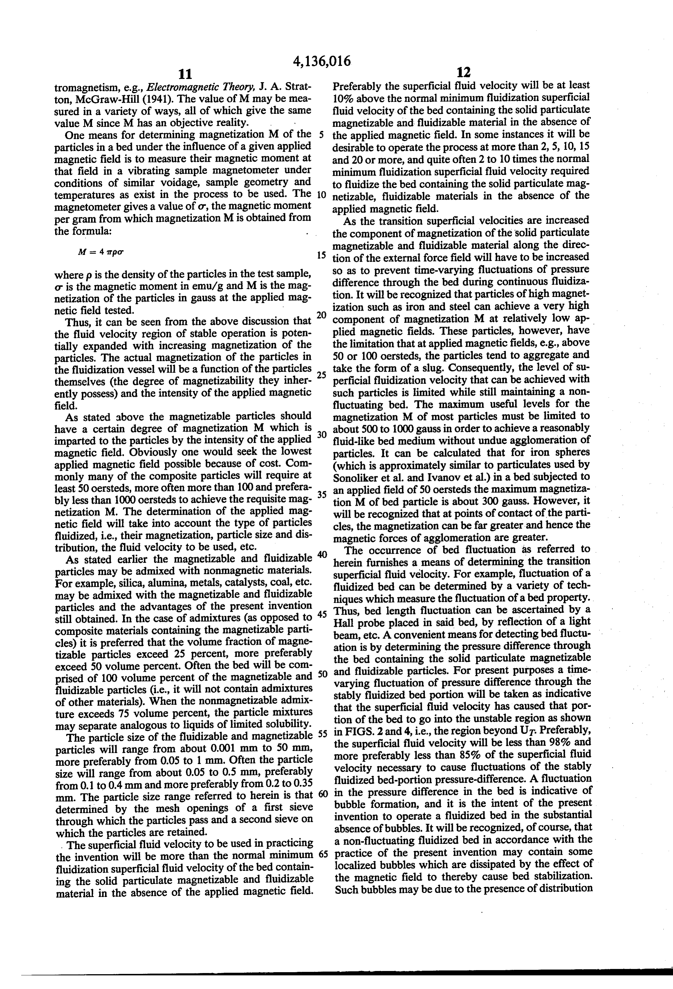
the stabilized, fluidized region (the operating region or The process of the instant invention enjoys benefits of zone of the present invention) and (3) the bubbling solids facilitated for transport and limited pressure drop fluidized region, as a function of applied magnetic field of a fluidized bed along with absence-of-backmixing intensity and stabilizing velocity. normally associated with fixed bed processes. FIG. 3 graphically illustrates the expansion of the When fluid is passed upward through a bed of closely magnetically stabilized fluidized bed in response to in sized granular solids, a pressure gradient is required to creasing gas flow at a constant applied magnetic field overcome friction. In order to increase the rate of flow, intensity. 10 a greater pressure gradient is required. When the pres FIG. 4 graphically illustrates the three phase regions, sure difference (also known as differential pressure and i.e., (1) the solid, unfluidized region, (2) the stabilized pressure drop A P) approaches the weight of the bed fluidized region and (3) the bubbling fluidized region as over a unit cross-sectional area, the solids begin to a function of applied magnetic field intensity. The ex move. This motion of the solids is created at superficial perimental system in this Figure is the same as used in 15 fluid velocities far below the terminal free-settling ve FIG. 3. The bed depths in this experimental systemma locities of the solid particles and constitutes the begin be read from FIG. 3. ning offluidization. Thus, the normal minimum fluidiza FIG. 5 graphically represents the pressure drop of tion superficial fluid gaseous or liquid velocity is the 177-250 micron steel (C1018) spheres as a function of fluid velocity observed when the pressure difference of superficial gas velocity at a uniform applied magnetic the fluid passing through the fluidized bed, as measured field of 48 oersteds. between upper and lower surfaces of the bed, is first FIG. 6 graphically represents a three phase diagram substantially the same as the bed weight per unit cross resulting from the plotting of the minimum fluidization sectional area. As is well known, superficial fluid veloc velocity and the transition fluidization velocity as a ity is a measure of the linear fluid velocity that would function of an applied uniform magnetic field. The ex 25 pass through an empty vessel and it is measured in feet perimental system is the same as used in FIG. 5. per second, centimeters per second, etc. This point of FIG. 7 illustrates a correlation of transition modulus normal minimum fluidization superficial fluid velocity N with transition velocity voidage e which supports in the absence of an applied magnetic field is the mini the conclusion of dimensional reasoning that a unique mum fluidization superficial fluid velocity of the pro relationship exists between these two variables for mag 30 cess of the invention.
netically saturated, long beds. The supported nickel For solid particulate magnetizable and fluidizable material has a density of 1.30 g/cm and a magnetization materials, the point of initial or minimum fluidization is of 5000 oersteds at an applied field of 228 gauss. not affected by the presence or absence of an applied magnetic field. However, when the minimum superfic
DETAILED DESCRIPTION OF THE 35 ial fluid velocity is exceeded in a bed which is not sub INVENTION jected to the influence of an applied magnetic field, the As indicated previously, the present invention relates porosity of the bed begins to increase and the individual to a process for operating a stably fluidized bed over a particles move under the influence of the passing fluids substantial range of fluid velocities. Fluid throughput concommitant with the formation of bubbles as shown rates which are 2, 5, 10, 15 and 20 or more times the in the left hand sketch of FIG. 1 of the drawings. Such normal minimum fluidization superficial fluid velocity a normally fluidized bed experiences gross solids circu of the bed containing the fluidizable material can be lation, gas bypassing, bubble formation, slugging and accomplished by the practice of the invention concom bed fluctuation. By comparison, with application of a mitant with substantial absence of gross solids circular magnetic field in accordance with the practice of the tion, very little or no gas bypassing and minimal or 45 present invention, the bed is stabilized, thereby reduc absence of bed fluctuation. The fluidized bed is stabi ing or eliminating: gas bypassing, bubble formation at lized by subjecting at least a portion of the fluidized bed the region or zone of the uniform magnetic field, slug comprising solid particulate magnetizable and fluidiza ging and bed fluctuation. Thus, a greater efficiency of ble material and a fluidizing fluid to a nontime varying fluid-solids contacting can be accomplished by operat (direct current) and substantially uniform applied mag 50 ing the process of the present invention. netic field having a substantial component along the As further illustration of the present invention, the direction of the external force field (which will gener phenomenon of normal fluidization can be visualized in ally be gravity) such that the solid particulate magnetiz terms of a simple experiment by the left hand sketch of able and fluidizable material has a component of mag FIG.1 in which a bed of solid particles is supported on netization along the direction of the external force field. 55 a horizontal porous grid in a vertical tube. A fluidizing As it will be seen from the description of the invention fluid in the form of a gaseous medium or liquid is then and reference to the drawings, the maximum superficial forced to flow upwards through the grid, and so fluid velocity that can be employed while still maintain through the particle bed. This flow causes a pressure ing a stable, nonfluctuating bed is a function of the difference (pressure drop) across the length of the bed, component of magnetization of the solid particulate and when this pressure difference is sufficient to support magnetizable and fluidizable material along the direc the weight of the particles, the bed is "incipiently fluid tion of the external force field which is imparted by the ized' (the superficial fluid velocity required to attain applied magnetic field. It is to be recognized that factors incipient fluidization is the "normal minimum superfic such as particle size, particle composition and shape, ial fluid velocity”). The fluidized bed thus formed has particle density, length and shape of the bed, etc. each many properties of a liquid; objects float on the surface affect the maximum fluidization velocity that can be and the addition or withdrawal of solid particles in achieved at a given component of magnetization. The process equipment is also facilitated. As shown by the variation and adjustment of these factors will be appar left hand sketch in FIG. 1, a gas-fluidized bed in which
Page 10
the gas velocity is greater than the incipient gas veloc decreases. When this Monel containing expanded bed ity, most of the excess gas passes through the bed as length is greater than 100 mm, the transition is indepen bubbles. dent of bed length and exceeds incipient fluidization By providing the solids of the bed with magnetizabil velocity by a factor of 2.3 at the applied field of 5000 ity and applying a uniform, time-steady magnetic field oersteds. At bed length less than 50 mm, the transition oriented parallel with the direction of gas flow as shown speed increases steeply as depth decreases, e.g., 4.6 in the right hand sketch in FIG. 1, it has been found that times greater than the incipient velocity at about 20mm a stabilized non-fluctuating and essentially bubble-free length. Additional experiments have shown that the fluidized bed results over a substantial range of superfic transition velocity of a stabilized bed is unaffected by ial gas velocities. As shown in the sketch in FIG. 1, the 10 the crosssection dimensions of the containing vessel for magnetic field may be conveniently furnished by tests in which the hydraulic diameter varied from 3 to wound coils carrying a modest direct electric current 28 centimeters.
and surrounding the fluidization vessel. When the transition velocity is determined by the Referring to FIG. 3 of the drawings, there is an illus method described above for a number of different ap tration of the response of magnetized solids to increase 15 plied field intensities, the results obtained give the plot of superficial gas velocity for a constant intensity of of FIG. 4 of the drawings (FIG. 2 which is similar to applied magnetic field. The solid particles are a closely FIG. 4 is discussed further with respect to the exam graded range of nickel-copper alloy (Monel). Measure ples). The experimental system used to provide the data ments of a particulate sample with a vibrating sample in FIG. 4 is the same as that used in FIG. 3 described magnetometer yield magnetization values of 372 gauss 20 above. The bed depths may be read from FIG. 3. FIG. at 5000 oersteds applied field, 326 gauss at 3000 oer 3 defines three regions that classify the physical state of steds, 250 gauss at 1000 oersteds and 132 gauss at 200 the bed emulsion as "unfluidized', 'stably fluidized,' or oersteds. The material is ferromagnetically soft with a "unstably fluidized.' The boundary between 'stably' and remanence of less than 5 gauss. With no gas flow the 'unstably fluidized' represents the transition described bed length is that of the randomly dumped solids. The 25 previously while the boundary between "unfluidized' bed comprises 2840 grams of the Monel (copper-nickel and 'stably fluidized' states represent incipient fluidiza alloy) of 177-250 micron particle size and specific grav tion. As will be demonstrated in the Examples, the ity of 8.45 in a vessel of 7.57 centimeter diameter with incipient fluidization is affected little or none by the an applied magnetic field intensity of 5000 oersteds that applied magnetic field intensity. For example, bed pres is uniform over the test region to within 1 percent. With sure difference initially is linear with flow rate, then a flow of air admitted to the vessel, the bed length is breaks at the point of incipient fluidization with pres unchanging up to the point of incipient fluidization. sure difference (pressure drop) about constant and Thereafter, the bed accommodates increasing flow by a closely equal to the bed weight per unit cross-sectional process of homogeneous expansion in which detectable area. The slope of the initial linear portion of the curve bubbles are not present in the bed and the bed of solids 35 is independent of applied field and it is predictable from in gas emulsion is free of fluctuation, agitation or solids the low velocity limit of the well known fixed bed circulation. In this stable, calm state, a visual inspection Ergun relationship. The invariance of the plateau pres of just the bed fails to reveal its fluid like nature. How sure level to the presence of the applied field verifies the ever, objects are readily immersed into the bed as into a force free nature of the uniform magnetic field. Since liquid and when released light objects float and dense 40 the incipient fluidization point corresponds to the inter objects sink. A hollow plastic sphere of 3.72 centimeter section of the said two lines, it follows that incipient diameter weighting 1.94 grams (ping pong ball) when fluidization is independent of applied magnetic field initially rotated continues to spin for several seconds, intensity.
thus indicating the very low frictional support it experi With velocity considered as analog to temperature or ences when floating partly submerged in the bed emul 45 agitation influence, and applied field as analog pressure, sion. As the superficial gas velocity (flow rate) is in FIG. 2 and FIG. 4 resemble a thermodynamic phase creased further, a point is ultimately reached where diagram of a pure substance having solid (unfluidized or bubbling suddenly commences. When the flow rate of fixed bed), liquid (stably fluidized) and vapor (unstably gas is slowly increased to the vicinity of the transition fluidized or boiling) regions. This two phase magne point, the bed surface in some instances bubbles over 50 tized flow in effect constitutes an aggregate composi part or all of its area for a limited time, then returns to tion of matter having unique thermodynamic and trans the motionless state; apparently the medium adjusts to a port properties.
new structure. A small incremental increase in through Uniformity of the emulsion can be inferred from pres put then produces steady bubbling and bed fluctuation. sure measurements using a capillary tube connected to a This flow rate is taken as the experimental transition 55 manometer and inserted vertically into the bed. It is point. The uncertainty introduced into the reported found that pressure increases linearly with depth imply values in this manneris on the order of 5% or less of the ing that voidage is uniform from one layer to the next superficial gas velocity. As shown by FIG. 3, this point throughout the bed.
of transition from the calmed or stabilized state of flow Orifice discharge tests confirm the ability to transfer to the state of bubbling and bed fluctuation occurs at 60 solids out of the containing vessel. The flow rate of the substantially higher flow rates than for the unmagne solids is characterized by a constant value of discharge tized bed. As shown in FIG. 3, no expansion occurs coefficient independent of applied field intensity or until the vicinity of UMF, the minimum throughput initial depth of the bed. Additional tests using bands of velocity causing bubbling in the absence of the applied surface pigmented solids as a color tracer demonstrate magnetic field. Expansion continues as gas flow in 65 that solids move through the bed in ideal piston-like creases with no bubbling, bed fluctuation or solids mix motion with no backmixing when a series of eight ing up to the point UT, the transition speed. It was found evenly spaced orifices are simultaneously opened that the transition velocity increases as the bed length around a circumference of the vessel cylindrical wall a
Page 11
short distance above the support grid. The plug nature electromagnet positioned to provide the vertically ori of the flow is participated in by all the bed particles, ented magnetic field. Another advantage of uniform including those adjacent to the wall. In this respect, the field is reduction of magnet power. Because the power bed emulsion behaves as an inviscid medium displaying requirements for a given mean field are less with more slip at the wall. At a distance on the order of the vessel uniform magnetic fields, it is preferred that variation of diameter above the orifices the flow must devitate from the varying magnetic field to the mean field in the bed simple one-dimensional motion. be no more than 100%, more preferably less than 50%, It has been found that orientation of the applied mag and most preferably less than 10%.
netic field is critical in achieving stable flow with the Generally, it will be shown that the greater the uni preferred direction colinear or parallel with the direc 10 formity of the applied field, the greater will be the ten tion of flow and hence vertical in these experiments. dency to form a homogeneous bed medium and one Experimental tests using a uniform transverse orienta which yields the greatest value of transition velocity. tion of applied field reveal that fluidization is achieved This fact furnishes the primary reason for utilizing uni but bubbling is not prevented, the bubbling occurring at form fields. Certain specific adverse influences of nonu the same throughput rate as in the absence of the ap 15 niform field distribution are illustrated in Examples 3, 6 plied magnetic field, that is at incipient fluidization. and 8 below.
These experiments comprised an applied magnetic field A spatially uniform DC field having a superposed AC of 570 - 20 oersteds over a short bed of 150-420 mi component behaves substantially as a DC field provided crons nickel-on alumina particles of specific gravity 1.3 the DC field intensity is substantially greater than the with bubbling occurring at 2.8 to 2.6 cm/s with and amplitude of the AC field component.
without the field. Applying 520 oersteds field parallel The solid particulate magnetizable and fluidizable with the flow deferred transition to the extraordinary particles to be used in the practice of the present inven value of 43 cm/s; the bed expanded by 68 percent of its tion are preferably particles having a low or zero coer initial length. civity. All ferromagnetic and ferrimagnetic substances, In putting the present invention into practice, the 25 including but not limited to magnetic Fe3O4 y-iron substantially uniform constant magnetic field is applied oxide (Fe2O3), ferrites of the form XO.Fe2O3, wherein to at least a portion or a zone of the fluidized bed con X is a metal or mixture of metals such as Zn, Mn, Cu, taining magnetizable, fluidizable solid particles. The etc.; ferromagnetic elements including iron, nickel, portion of the bed or series of beds to be stabilized may cobalt and gadolinium, alloys of ferromagnetic ele be designed to suite the particular process to use the 30 ments, etc. may be used as the magnetizable and fluidiz process of the invention. For example, in some fluidiza able particulate solids. Other non-magnetic materials tion processes, it may be expedient to stabilize the up may be coated with and/or contain dispersed therein permost 10-40% or 1/3 region or zone of the bed while solids having the quality of ferromagnetism. For exam purposely allowing the remaining region or zone of the ple, composites of magnetizable and fluidizable solid bed to be unstable. Alternatively, the fluidization vessel 35 particulates, for example in some catalytic processes may be disposed of separate and discrete sections, at may contain from 2 to 40 volume percent and prefera least one of which is stabilized by the process of the bly 5 to 20 volume percent and more preferably 10-15 present invention. In both of such instances, it is pre volume percent of the ferro- or ferrimagnetic material ferred that the region is stabilized by the applied mag and the balance of the composite will be comprised of netic field having a variation of its vertical component nonmagnetic material. Often it will be desirable to use a that does not exceed 25% of the average vertical com ferro- or ferrimagnetic composite with a nonmagnetic ponent over the region or zone of the bed to be stabi catalytic material. The fluidized bed containing the lized, said region containing the particulate magnetiz composites may also include particulate solids which able and fluidizable material. Preferably, the magnetic are nonmagnetizable. In other processes it may be desir intensity will vary no more than 10% and more prefera 45 able to use 100% ferro- or ferrimagnetic materials as the bly no more than 5% over the stabilized region. Often, particulate solids, it will be deemed desirable to design such regions or An important factor in selecting or preparing the zones to have only about a 5% or less variance, magnetizable and fluidizable particulate solids is the In many processes it will be desirable that the entire magnetization M of the particle. The higher the magnet fluidized bed in a fluidization vessel be stabilized in 50 ization M of the particle, the higher will be the transi accordance with the teachings of the present invention. tion velocity UT up to which the bed may be operated In such cases, the widest range of stable behavior of the without bubbling and bed fluctuation, all other factors fluidized medium is obtained when the applied mag such as particle size and distribution being held con netic field is substantially uniform throughout the entire stant. The magnetization of the magnetizable and flui bed containing the magnetizable and fluidizable solid SS dizable particles in the medium will have a magnetiza particles. Thus, when the magnetic field is applied hav tion M of at least 10 gauss. Generally for high fluid ing a substantial vertical component to stabilize the velocities, the particles will have a magnetization, as fluidized medium, the variation of the vertical compo being imparted by the applied magnetic field, of at least nent of the magnetic field to the mean field in the bed 50 gauss, preferably at least 100 gauss and more prefera must be no greater than 50%, and most preferably no bly at least about 150 gauss, e.g., 150-400 gauss. For greater than 10%. Often, such fluidization units will be those processes requiring very high fluid velocities, the designed to have a less than 5% variation over the magnetization of the magnetizable, fluidizable particles 8. may be up to about 1000 gauss or more, but preferably As demonstrated in Table IX, Example 7 below, it 150-450 gauss.
has been unexpectedly found that nontime varying ver The magnetization M of the particles, as is well tical fields are preferred and provide advantages over known, is defined as B-H in the particle, where B is the time varying fields, that is direct current (DC) rather magnetic induction and H is the magnetic field, the than an alternating current (AC) is used to energize the fields being defined in standard published works in elec
Page 12
tromagnetism, e.g., Electromagnetic Theory, J. A. Strat Preferably the superficial fluid velocity will be at least ton, McGraw-Hill (1941). The value of M may be mea 10% above the normal minimum fluidization superficial sured in a variety of ways, all of which give the same fluid velocity of the bed containing the solid particulate value M since M has an objective reality. magnetizable and fluidizable material in the absence of One means for determining magnetization M of the 5 the applied magnetic field. In some instances it will be particles in a bed under the influence of a given applied desirable to operate the process at more than 2, 5, 10, 15 magnetic field is to measure their magnetic moment at and 20 or more, and quite often 2 to 10 times the normal that field in a vibrating sample magnetometer under minimum fluidization superficial fluid velocity required conditions of similar voidage, sample geometry and to fluidize the bed containing the solid particulate mag temperatures as exist in the process to be used. The 10 netizable, fluidizable materials in the absence of the magnetometer gives a value of ot, the magnetic moment applied magnetic field.
per gram from which magnetization M is obtained from As the transition superficial velocities are increased the formula: the component of magnetization of the solid particulate M = 4 arpo magnetizable and fluidizable material along the direc 15 tion of the external force field will have to be increased so as to prevent time-varying fluctuations of pressure where p is the density of the particles in the test sample, difference o is the magnetic moment in emu/g and M is the mag through the bed during continuous fluidiza netization of the particles in gauss at the applied mag tion. It will be recognized that particles of high magnet netic field tested. 20 ization such as iron and steel can achieve a very high
Thus, it can be seen from the above discussion that component of magnetization M at relatively low ap the fluid velocity region of stable operation is poten plied magnetic fields. These particles, however, have tially expanded with increasing magnetization of the the limitation that at applied magnetic fields, e.g., above particles. The actual magnetization of the particles in 50 or 100 oersteds, the particles tend to aggregate and the fluidization vessel will be a function of the particles 25 take the form of a slug. Consequently, the level of su themselves (the degree of magnetizability they inher perficial fluidization velocity that can be achieved with ently possess) and the intensity of the applied magnetic such particles is limited while still maintaining a non field. fluctuating bed. The maximum useful levels for the As stated above the magnetizable particles should magnetization M of most particles must be limited to have a certain degree of magnetization M which is about 500 to 1000 gauss in order to achieve a reasonably imparted to the particles by the intensity of the applied 30 fluid-like bed medium without undue agglomeration of magnetic field. Obviously one would seek the lowest particles. It can be calculated that for iron spheres applied magnetic field possible because of cost. Com (which is approximately similar to particulates used by monly many of the composite particles will require at Sonoliker et al. and Ivanov et al.) in a bed subjected to least 50 oersteds, more often more than 100 and prefera 35 an applied field of 50 oersteds the maximum magnetiza bly less than 1000 oersteds to achieve the requisite mag tion M of bed particle is about 300 gauss. However, it netization M. The determination of the applied mag will be recognized that at points of contact of the parti netic field will take into account the type of particles cles, the magnetization can be far greater and hence the fluidized, i.e., their magnetization, particle size and dis magnetic forces of agglomeration are greater. tribution, the fluid velocity to be used, etc. The occurrence of bed fluctuation as referred to As stated earlier the magnetizable and fluidizable herein furnishes a means of determining the transition particles may be admixed with nonmagnetic materials. superficial fluid velocity. For example, fluctuation of a For example, silica, alumina, metals, catalysts, coal, etc.
may be admixed with the magnetizable and fluidizable fluidized niques bed can be determined by a variety of tech which measure the fluctuation of a bed property.
particles and the advantages of the present invention 45 Thus, bed length still obtained. In the case of admixtures (as opposed to Hall probe placed fluctuation in said bed, can be ascertained by a by reflection of a light composite materials containing the magnetizable parti beam, etc. A convenient means for cles) it is preferred that the volume fraction of magne ation is by determining the pressuredetecting bed fluctu difference through tizable particles exceed 25 percent, more preferably the bed containing the solid particulate magnetizable exceed 50 volume percent. Often the bed will be com prised of 100 volume percent of the magnetizable and 50 and fluidizable particles. For present purposes a time varying fluctuation of pressure difference through the fluidizable particles (i.e., it will not contain admixtures stably fluidized bed portion will be taken as indicative of other materials). When the nonmagnetizable admix that the superficial ture exceeds 75 volume percent, the particle mixtures tion of the bed to gofluid velocity has caused that por into the unstable region as shown may separate analogous to liquids of limited solubility. in FIGS. 2 and 4, i.e., the region beyond UT Preferably, The particle size of the fluidizable and magnetizable 55 the superficial fluid velocity will be less than 98% and particles will range from about 0.001 mm to 50 mm, more preferably less than 85% of the superficial fluid more preferably from 0.05 to 1 mm. Often the particle velocity necessary to cause fluctuations size will range from about 0.05 to 0.5 mm, preferably fluidized bed-portion pressure-difference. Aoffluctuation the stably from 0.1 to 0.4mm and more preferably from 0.2 to 0.35 in the pressure difference in the bed is indicative of mm. The particle size range referred to herein is that bubble determined by the mesh openings of a first sieve inventionformation, and it is the intent of the present through which the particles pass and a second sieve on absence oftobubbles. operate a fluidized bed in the substantial It will be recognized, of course, that which the particles are retained.
. The superficial fluid velocity to be used in practicing apractice non-fluctuating fluidized bed in accordance with the of the present invention may contain some the invention will be more than the normal minimum 65 fluidization superficial fluid velocity of the bed contain the localized bubbles which are dissipated by the effect of ing the solid particulate magnetizable and fluidizable Suchmagnetic field to thereby cause bed stabilization. bubbles may be due to the presence of distribution material in the absence of the applied magnetic field.
Page 13
means for introducing or removing fluids or solids from. fluid velocity required to cause a 0.1% ratio of root the fluidization vessel, the presence of obstructions of mean square fluctuation of pressure difference to mean the flow, momentary pulses in flow rate of the solids or pressure difference through the bed during continuous fluid in the vessel etc. In any event, the superficial fluid fluidization. . . . velocity should be controlled or monitored such that it 5. It is to be understood that the value of 0.1% is not to is less than the superficial fluid velocity required to be construed as those attributed to fluctuations of pres cause time-varying fluctuations of pressure difference sure difference readings due to the grid, distributor through the stably fluidized bed portion over a finite means for introducing or removing fluids or solids from period of time, e.g., 0.1 to 1, preferably 1 to 10 seconds, the fluidization vessel, etc. and more preferably 10 to 100 second intervals during 10 continuous fluidization. The term fluctuations of pres sure difference through the stably fluidized bed portion,
THEORY OF THE INVENTION
While not wishing to be bound by any theory, the as referred to herein, is meant to be restricted to those following theoretical explanation is offered for the pur fluctuations attributed to the fluidization process itself as a result of the fluid, i.e., gaseous material causing the 15 pose
of further illustration of the invention.
Hydrodynamic stability analysis has revealed that the fluidization, and not external sources of vibrations uniformly magnetized medium in a long bed undergoes which may cause minor fluctuations of pressure read transition from the stably fluidized state in which there ings, e.g., motors, fans, pumps, or due to the grid in the is no bubbling to the unstable bubbling state of motion bed, etc. . .. . - under conditions specified by the following stability
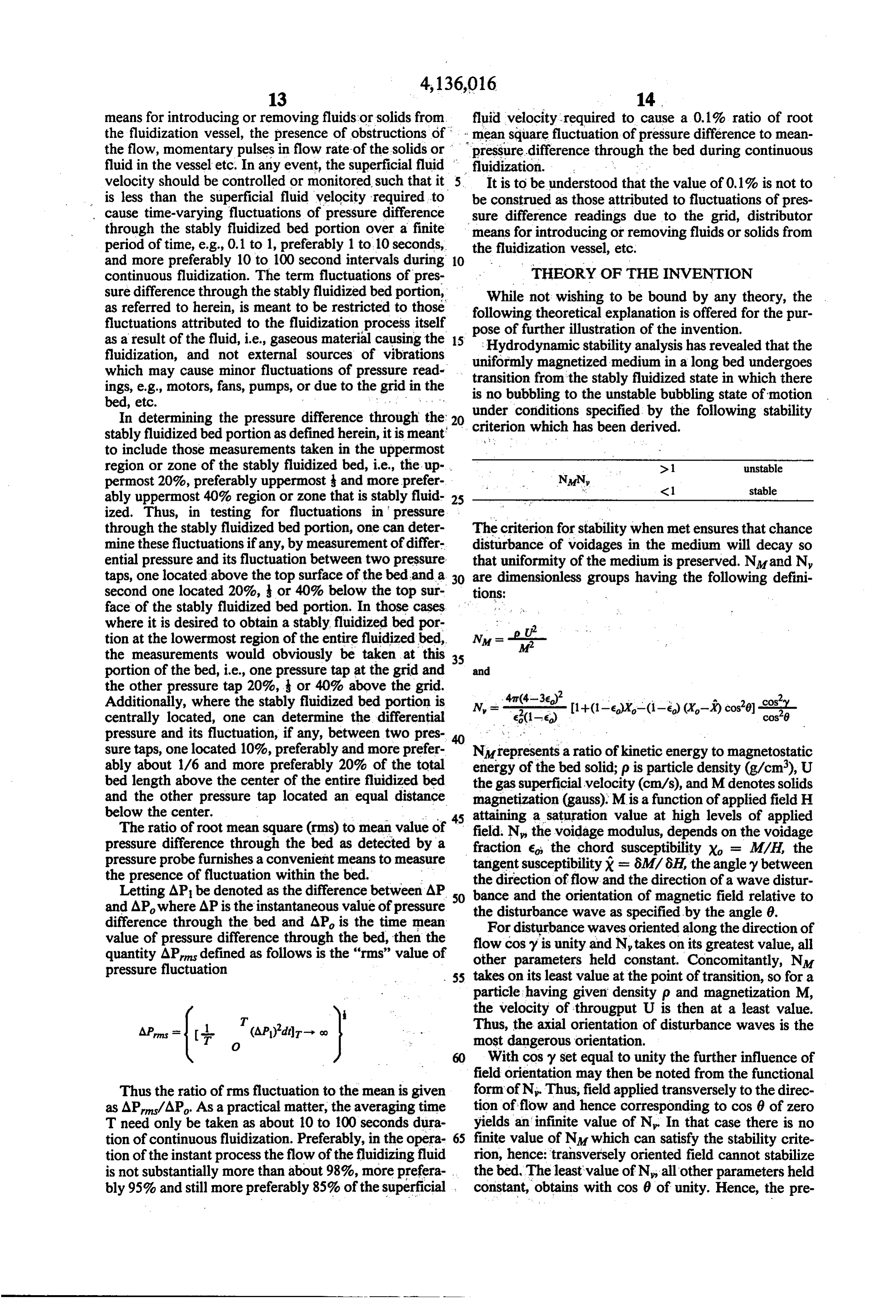
In determining the pressure difference through the 20 criterion which has been derived stably fluidized bed portion as defined herein, it is meant to include those measurements taken in the uppermost region or zone of the stably fluidized bed, i.e., the up >1 unstable permost 20%, preferably uppermost and more prefer NMN <1 stable ably uppermost 40% region or zone that is stably fluid- 25 ized. Thus, in testing for fluctuations in pressure through the stably fluidized bed portion, one can deter The criterion for stability when met ensures that chance mine these fluctuations if any, by measurement of differ disturbance of voidages in the medium will decay so ential pressure and its fluctuation between two pressure that uniformity of the medium is preserved. Nand N, taps, one located above the top surface of the bed and a 30 are dimensionless groups having the following defini second one located 20%, or 40% below the top sur tions: - face of the stably fluidized bed portion. In those cases where it is desired to obtain a stably fluidized bed por Up tion at the lowermost region of the entire fluidized bed, N=-- the measurements would obviously be taken at this 35 portion of the bed, i.e., one pressure tap at the grid and and the other pressure tap 20%, or 40% above the grid.
Additionally, where the stably fluidized bed portion is a
centrally located, one can determine the differential c1-6) pressure and its fluctuation, if any, between two pres sure taps, one located 10%, preferably and more prefer NM represents a ratio of kinetic energy to magnetostatic ably about 1/6 and more preferably 20% of the total energy of the bed solid; p is particle density (g/cm), U bed length above the center of the entire fluidized bed the gas superficial velocity (cm/s), and Mdenotes solids and the other pressure tap located an equal distance magnetization (gauss). Mis a function of applied field H below the center. attaining a saturation value at high levels of applied The ratio of root mean square (rms) to mean value of 45 field. N, the voidage modulus, depends on the voidage pressure difference through the bed as detected by a fraction e, the chord susceptibility X = M/H, the pressure probe furnishes a convenient means to measure tangent susceptibility x = 8M/6H, the angley between the presence of fluctuation within the bed. the direction offlow and the direction of a wave distur Letting AP be denoted as the difference between AP 50 bance and the orientation of magnetic field relative to and AP, where AP is the instantaneous value of pressure the disturbance wave as specified by the angle 0. difference through the bed and AP is the time mean For disturbance waves oriented along the direction of value of pressure difference through the bed, then the flow quantity AP defined as follows is the "rims' value of othercos y is unity and N, takes on its greatest value, all parameters held constant. Concomitantly, N.
pressure fluctuation 55 takes on its least value at the point of transition, so for a particle having given density p and magnetization M, the velocity of througput U is then at a least value.
APrms = (r O (AP)'d-o 2 Thus, the axial orientation of disturbance waves is the most dangerous orientation.
With cos y set equal to unity the further influence of field orientation may then be noted from the functional
Thus the ratio of rms fluctuation to the mean is given form of N. Thus, field applied transversely to the direc as AP/AP. As a practical matter, the averaging time tion of flow and hence corresponding to cos 0 of zero T need only be taken as about 10 to 100 seconds dura yields an infinite value of N. In that case there is no tion of continuous fluidization. Preferably, in the opera- 65 finite value of NM which can satisfy the stability crite tion of the instant process the flow of the fluidizing fluid rion, hence: transversely oriented field cannot stabilize is not substantially more than about 98%, more prefera the bed. The least value of N, all other parameters held bly 95% and still more preferably 85% of the superficial constant, obtains with cos 0 of unity. Hence, the pre
Page 14
ferred orientation of magnetic field is parallel with the fluidizable particulate solids, said particulate solids in flow direction, that is, vertically oriented. The stability cluding a plurality of separate, discrete magnetizable criterion discussed above relates to a modelled bed of particles, a bed fluidizing medium, preferably a gas, and unbounded extent. Observed throughputs for actual means for generating a magnetic field operably con bounded beds range from "equal to' to "greater than' 5 nected to said vessel in such a manner that the magnetic the estimate of throughput provided by the said crite field permeates substantially the total volume of said rion. Hence it will be understood that the instant inven fluidized bed, is of a uniform nature, and is oriented tion is not meant to be limited by the said criterion. with a substantial vertical component to the flow of Ideally the magnetic field should be uniform through fluid through said fluidized bed.
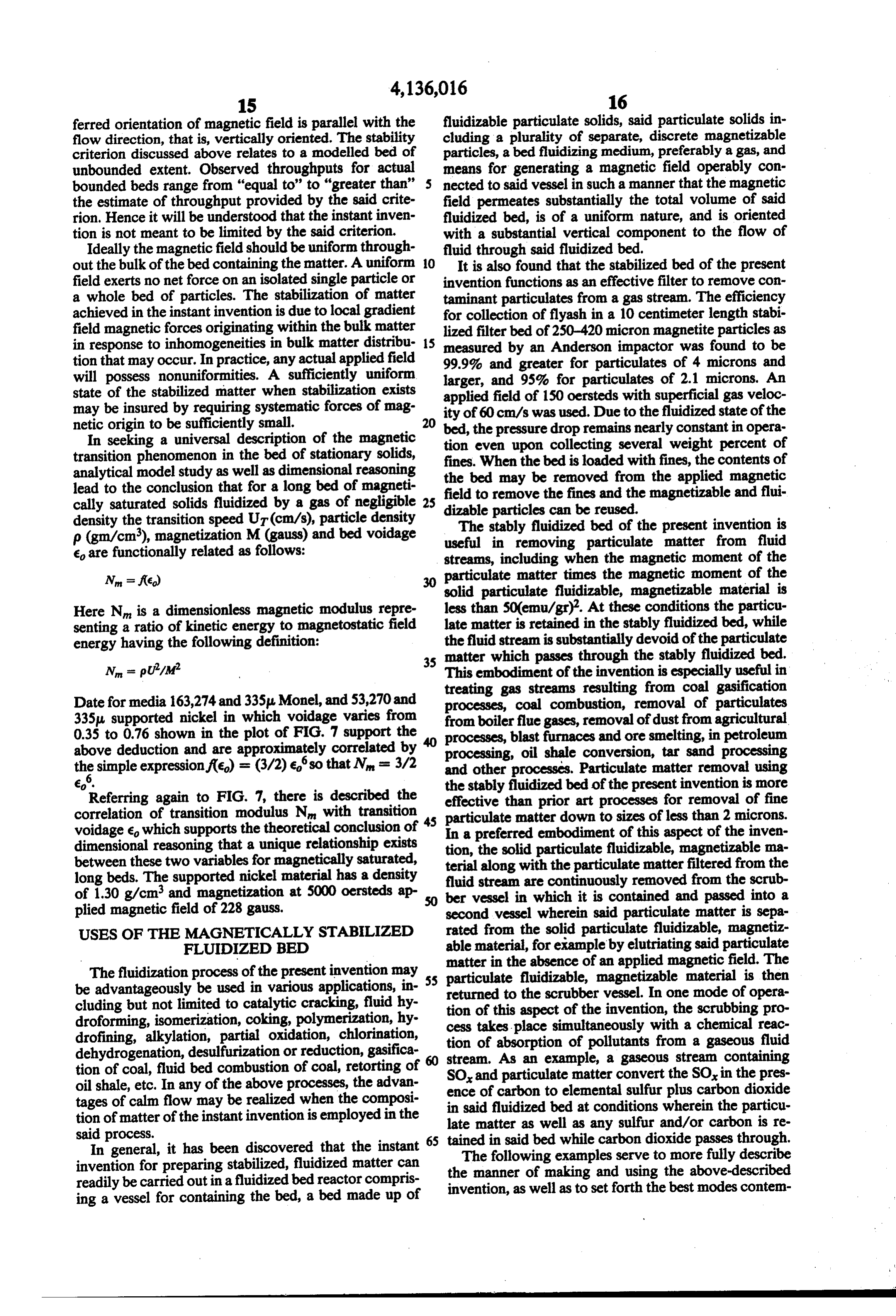
out the bulk of the bed containing the matter. A uniform O It is also found that the stabilized bed of the present field exerts no net force on an isolated single particle or invention functions as an effective filter to remove con a whole bed of particles. The stabilization of matter taminant particulates from a gas stream. The efficiency achieved in the instant invention is due to local gradient for collection of flyash in a 10 centimeter length stabi field magnetic forces originating within the bulk matter lized filter bed of 250-420 micron magnetite particles as in response to inhomogeneities in bulk matter distribu 15 measured by an Anderson impactor was found to be tion that may occur. In practice, any actual applied field 99.9% and greater for particulates of 4 microns and will possess nonuniformities. A sufficiently uniform larger, and 95% for particulates of 2.1 microns. An state of the stabilized matter when stabilization exists may be insured by requiring systematic forces of mag applied ity of 60 field of 150 oersteds with superficial gas veloc cm/s was used. Due to the fluidized state of the netic origin to be sufficiently small. 20 bed, the pressure drop remains nearly constant in opera In seeking a universal description of the magnetic tion even upon collecting several weight percent of transition phenomenon in the bed of stationary solids, fines. When the bed is loaded with fines, the contents of analytical model study as well as dimensional reasoning the bed may be removed from the applied magnetic lead to the conclusion that for a long bed of magneti field to remove the fines and the magnetizable and flui cally saturated solids fluidized by a gas of negligible 25 dizable particles can be reused. density the transition speed UT (cm/s), particle density The stably fluidized bed of the present invention is p (gm/cm), magnetization M (gauss) and bed voidage useful in removing particulate matter from fluid e are functionally related as follows: streams, including when the magnetic moment of the Nn = f(e) 30 particulate matter times the magnetic moment of the solid particulate fluidizable, magnetizable material is
Here N is a dimensionless magnetic modulus repre less than 50(emu/gr). At these conditions the particu senting a ratio of kinetic energy to magnetostatic field late matter is retained in the stably fluidized bed, while energy having the following definition: the fluid stream is substantially devoid of the particulate 35 matter which passes through the stably fluidized bed,
This embodiment of the invention is especially useful in treating gas streams resulting from coal gasification
Date for media 163,274 and 335u Monel, and 53,270 and processes, coal combustion, removal of particulates 335 supported nickel in which voidage varies from from boiler flue gases, removal of dust from agricultural 0.35 to 0.76 shown in the plot of FIG. 7 support the processes, blast furnaces and ore smelting, in petroleum above deduction and are approximately correlated by 40 processing, oil shale conversion, tar sand processing th simple expression f(e) = (3/2) eso that N = 3/2 and other processes. Particulate matter removal using e. the stably fluidized bed of the present invention is more Referring again to FIG. 7, there is described the effective than prior art processes for removal of fine correlation of transition modulus N with transition particulate matter down to sizes of less than 2 microns. voidage 6, which supports the theoretical conclusion of In dimensional reasoning that a unique relationship exists tion,a preferred embodiment of this aspect of the inven the solid particulate fluidizable, magnetizable ma between these two variables for magnetically saturated, terial along with the particulate matter filtered from the long beds. The supported nickel material has a density fluid stream are continuously removed from the scrub of 1.30 g/cm and magnetization at 5000 oersteds ap 50 ber vessel in which it is contained and passed into a plied magnetic field of 228 gauss. second vessel wherein said particulate matter is sepa USES OF THE MAGNETICALLY STABLIZED rated from the solid particulate fluidizable, magnetiz FLUIDIZED BED able material, for example by elutriating said particulate matter in the absence of an applied magnetic field. The
The fluidization process of the present invention may 55 particulate be advantageously be used in various applications, in returned to fluidizable, magnetizable material is then cluding but not limited to catalytic cracking, fluid hy tion of this aspect of the vessel.
the scrubber In one mode of opera droforming, isomerization, coking, polymerization, hy cess takes place simultaneously withthea scrubbing invention, chemical pro reac drofining, alkylation, partial oxidation, chlorination, tion of absorption of pollutants from a gaseous fluid dehydrogenation, desulfurization or reduction, gasifica tion of coal, fluid bed combustion of coal, retorting of 60 stream.
SO, and
As an example, a gaseous stream containing particulate matter convert the SO, in the pres oil shale, etc. In any of the above processes, the advan ence of carbon tages of calm flow may be realized when the composi in said fluidizedtobedelemental at sulfur plus carbon dioxide conditions wherein the particu tion of matter of the instant invention is employed in the late matter as well as any sulfur and/or carbon is re said process. 65 tained in said bed while carbon dioxide passes through. In general, it has been discovered that the instant invention for preparing stabilized, fluidized matter can theThe following examples serve to more fully describe manner of making and using the above-described readily be carried out in a fluidized bed reactor compris invention, as well as to set forth the best modes contem ing a vessel for containing the bed, a bed made up of
Page 15
plated for carrying out various aspects of the invention. TABLE I-continued It is understood that these examples in no way serve to Applied Field Transition Superficial Bed Depth, limit the true scope of this invention, but rather are Oersteds Velocity, cm/s presented for illustrative purposes. It will be understood 12S 21 29 that all proportions are in parts by weight, unless other 280
wise indicated. 520 43 37
EXAMPLE 1.
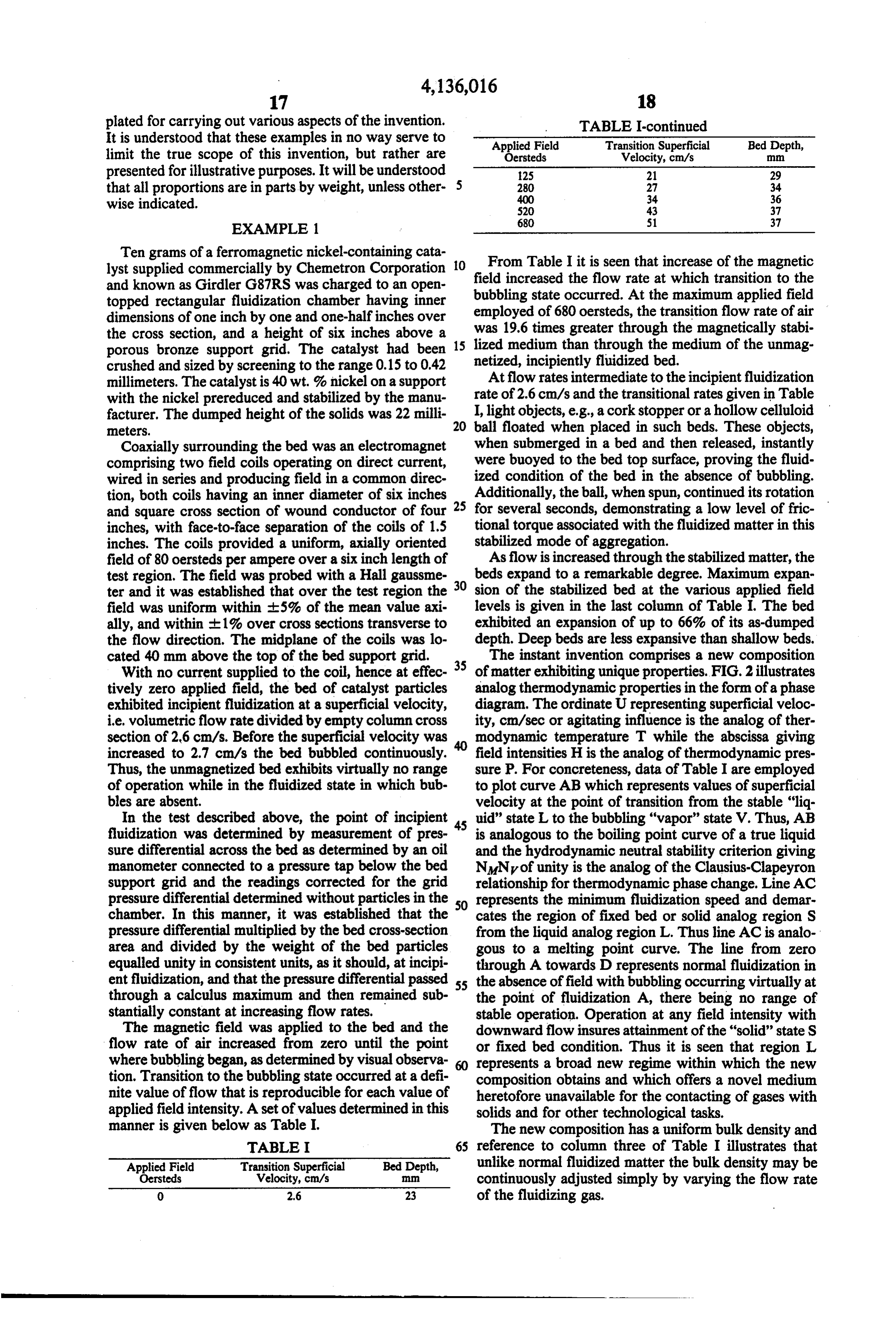
Tengrams of a ferromagnetic nickel-containing cata lyst supplied commercially by Chenetron Corporation O fieldFrom Table I it is seen that increase of the magnetic increased the flow rate at which transition to the and known as Girdler G87RS was charged to an open bubbling state occurred. At the maximum applied field topped rectangular fluidization chamber having inner employed of 680 oersteds, dimensions of one inch by one and one-halfinches over was 19.6 times greater through the transition flow rate of air the magnetically stabi the cross section, and a height of six inches above a 15 lized medium than through the medium porous bronze support grid. The catalyst had been of the unmag crushed and sized by screening to the range 0.15 to 0.42 netized, incipiently fluidized bed. millimeters. The catalyst is 40 wt.% nickel on a support At flow rates intermediate to the incipient fluidization with the nickel prereduced and stabilized by the manu rate of 2.6 cm/s and the transitional rates given in Table facturer. The dumped height of the solids was 22 milli I, light objects, e.g., a cork stopper or a hollow celluloid meters. ball floated when placed in such beds. These objects, Coaxially surrounding the bed was an electromagnet when submerged in a bed and then released, instantly comprising two field coils operating on direct current, were buoyed to the bed top surface, proving the fluid wired in series and producing field in a common direc ized condition of the bed in the absence of bubbling. tion, both coils having an inner diameter of six inches 25 Additionally, the ball, when spun, continued its rotation and square cross section of wound conductor of four for several seconds, demonstrating a low level of fric inches, with face-to-face separation of the coils of 1.5 tional torque associated with the fluidized matter in this inches. The coils provided a uniform, axially oriented stabilized mode of aggregation.
field of 80 oersteds per ampere over a six inch length of As flow is increased through the stabilized matter, the test region. The field was probed with a Hall gaussme 30 beds expand to a remarkable degree. Maximum expan ter and it was established that over the test region the sion of the stabilized bed at the various applied field field was uniform within -.5% of the mean value axi levels is given in the last column of Table I. The bed ally, and within E1% over cross sections transverse to exhibited an expansion of up to 66% of its as-dumped the flow direction. The midplane of the coils was lo depth. Deep beds are less expansive than shallow beds. cated 40 mm above the top of the bed support grid. 35 The instant invention comprises a new composition With no current supplied to the coil, hence at effec of matter exhibiting unique properties. FIG. 2 illustrates tively zero applied field, the bed of catalyst particles analog thermodynamic properties in the form of a phase exhibited incipient fluidization at a superficial velocity, diagram. The ordinate U representing superficial veloc i.e. volumetric flow rate divided by empty column cross ity, cm/sec or agitating influence is the analog of ther section of 2.6 cm/s. Before the superficial velocity was modynamic temperature T while the abscissa giving increased to 2.7 cm/s the bed bubbled continuously. field intensities His the analog of thermodynamic pres Thus, the unmagnetized bed exhibits virtually no range sure P. For concreteness, data of Table I are employed of operation while in the fluidized state in which bub to plot curve AB which represents values of superficial bles are absent. velocity at the point of transition from the stable "liq In the test described above, the point of incipient 45 uid” state L to the bubbling "vapor' state V. Thus, AB fluidization was determined by measurement of pres is analogous to the boiling point curve of a true liquid sure differential across the bed as determined by an oil and the hydrodynamic neutral stability criterion giving manometer connected to a pressure tap below the bed NNyof unity is the analog of the Clausius-Clapeyron support grid and the readings corrected for the grid relationship for thermodynamic phase change. Line AC pressure differential determined without particles in the 50 represents the minimum fluidization speed and demar chamber. In this manner, it was established that the cates the region of fixed bed or solid analog region S pressure differential multiplied by the bed cross-section from the liquid analog region L. Thus line AC is analo area and divided by the weight of the bed particles gous to a melting point curve. The line from zero equalled unity in consistent units, as it should, at incipi through A towards D represents normal fluidization in ent fluidization, and that the pressure differential passed 55 the absence of field with bubbling occurring virtually at through a calculus maximum and then remained sub the point of fluidization A, there being no range of stantially constant at increasing flow rates. stable operation. Operation at any field intensity with The magnetic field was applied to the bed and the downward flow insures attainment of the "solid” state S flow rate of air increased from zero until the point or fixed bed condition. Thus it is seen that region L where bubbling began, as determined by visual observa 60 represents a broad new regime within which the new tion. Transition to the bubbling state occurred at a defi composition obtains and which offers a novel medium nite value of flow that is reproducible for each value of heretofore unavailable for the contacting of gases with applied field intensity. A set of values determined in this solids and for other technological tasks. manner is given below as Table I. The new composition has a uniform bulk density and TABLE I 65 reference to column three of Table I illustrates that Applied Field Transition Superficial Bed Depth, unlike normal fluidized matter the bulk density may be Oersteds Velocity, cm/s continuously adjusted simply by varying the flow rate O 2.6 23 of the fluidizing gas.
Page 16
Transport properties of the new composition are EXAMPLE 3 unique as well. For example, heat conductivity is far lower than for normal fluidized matter. At the transition Effect of Transverse Magnetic Field Gradients point the matter undergoes a change in the nature of a The 1 inch X 1 inch X 6inch fluidization chamber phase change becoming bubbling fluidized matter pos- 5 with the G87RS bed particles of Example 1 was sub sessing dramatic increase in heat conductivity. Many jected to the magnetic field of a ceramic permanent other examples could be cited of distinctive properties magnet having the dimensions 2 inch X 1 inch x inch such as the rheological properties, electrical properties with the direction of magnetization through the inch and so forth. dimension. The magnetic field of the magnet is given in Later in Example 4 it is demonstrated that unlike 10 Table III for various positions along the perpendicular normal fluidized matter but like a true liquid the matter from the center of the magnet's 2 inch by 1 inch pole of region L shows limited solubility effects. face. The variation of magnetic field in the transverse EXAMPLE 2 direction across the bed is about 168% relative to the mean field.
In this example the direction of the magnetic field 15 TABLE III was transverse to the direction of air flow. The field was provided by a pair of ceramic permanent magnet Position, s Magnetic Field, H
plates having pole face dimensions of 6 inches by 3 0 420 inches and each a thickness of inch. Spaced 1 inches 20 1 340 from face to face, these magnets produced a uniform 2
magnetic field of 570 - 20 oersteds over the test region. 4. 90
The mid-plane of the magnetic plates was located 1 inch above the bed support grid. In the range of positions given, the gradient of field is The bed and bed solids were the same as in Example nearly constant, producing a maximum body force in
The response of this bed to increasing air flow rate is the direction transverse to the flow of about 1.3 times given in Table II below. the force of gravity. This force ratio was computed
TABLE II
from the relationship (47tpg) MdH/ds with g = 980 cm/s, p = 1.3 g/cm, dH/ds in units of oersteds/cm,
TRANSVERSE ORIENTATION OF FIELD 30 assuming the value M = 168 gauss.
Field Superficial Bed The magnet's 2 inch X 1 inch pole face was stationed Intensity, Flow Rate, Depth, Fluid Bub
Oersteds cm/s ization bling injuxtaposition with the outside of inch thick walls of 570 22 No the vessel, at various stations along the bed bulk. As the
Yes result, fluidization was prevented at all flow rates over
570 38 Yes the range 0 to 60 cm/s. The nonuniform applied mag 570 b) 29 Yes netic field locked the particles against each other and The bed was levitated or fluidized as evidenced by the expansion of the bed but the container wall, preventing fluidization. the bed medium failed to float a test cork.
The bed exhibited violent slugging with chaotic flow at flow rates in excess of 2.8
The utility of the magnetically stabilized composition cm/sec. is expanded using admixtures of magnetizable solids 40 with nonmagnetizable particulates as shown in the next
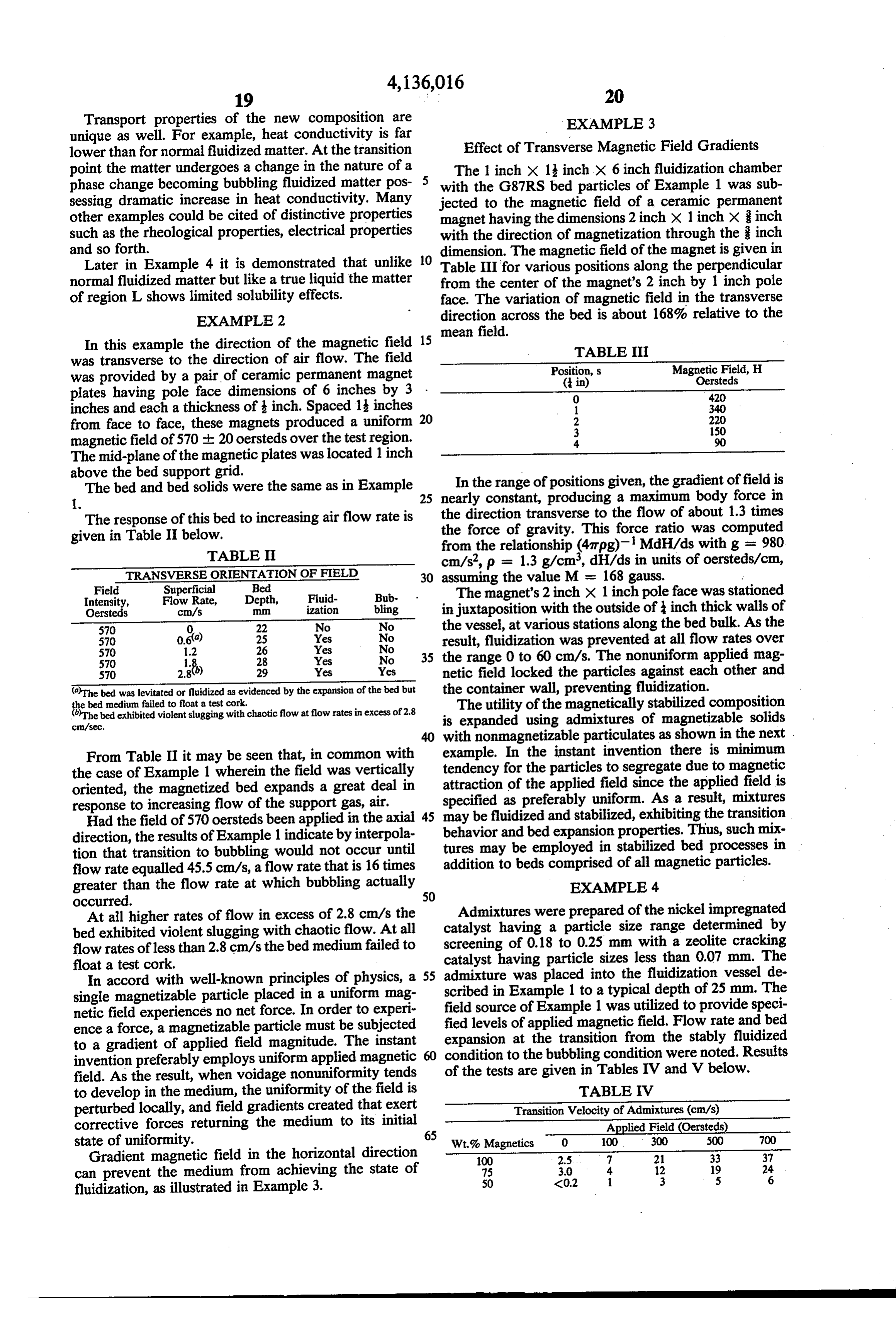
From Table II it may be seen that, in common with example. In the instant invention there is minimum the case of Example 1 wherein the field was vertically tendency for the particles to segregate due to magnetic oriented, the magnetized bed expands a great deal in attraction of the applied field since the applied field is response to increasing flow of the support gas, air. specified as preferably uniform. As a result, mixtures Had the field of 570 oersteds been applied in the axial 45 behavior may be fluidized and stabilized, exhibiting the transition direction, the results of Example 1 indicate by interpola tures mayand bed expansion properties. Thus, such mix tion that transition to bubbling would not occur until addition tobe employed in stabilized bed processes in beds comprised of all magnetic particles.
flow rate equalled 45.5 cm/s, a flow rate that is 16 times greater than the flow rate at which bubbling actually EXAMPLE 4 occurred. 50
At all higher rates of flow in excess of 2.8 cm/s the catalyst Admixtures were prepared of the nickel impregnated bed exhibited violent slugging with chaotic flow. At all screening having a particle size range determined by flow rates of less than 2.8 cm/s the bed medium failed to catalyst having of 0.18 to 0.25 mm with a zeolite cracking float a test cork. particle sizes less than 0.07 mm. The In accord with well-known principles of physics, a 55 admixture was placed into the fluidization vessel de single magnetizable particle placed in a uniform mag scribed in Example 1 to a typical depth of 25 mm. The netic field experiences no net force. In order to experi field source of Example 1 was utilized to provide speci ence a force, a magnetizable particle must be subjected fied levels of applied magnetic field. Flow rate and bed to a gradient of applied field magnitude. The instant expansion at the transition from the stably fluidized invention preferably employs uniform applied magnetic 60 condition to the bubbling condition were noted. Results field. As the result, when voidage nonuniformity tends of the tests are given in Tables IV and V below.
to develop in the medium, the uniformity of the field is TABLE IV perturbed locally, and field gradients created that exert Transition Velocity of Admixtures (cm/s) corrective forces returning the medium to its initial Applied Field (Oersteds) state of uniformity. Wt.% Magnetics O 100 300 500 700 Gradient magnetic field in the horizontal direction 100 2.5 7 21 33 37 can prevent the medium from achieving the state of 75
fluidization, as illustrated in Example 3.
Page 17
TABLE IV-continued . . .. . . .. . , , 2 Transition Velocity of Admixtures (cm/s) . .
Wt.% Magnetics 0 100 300 500 . . . .700.
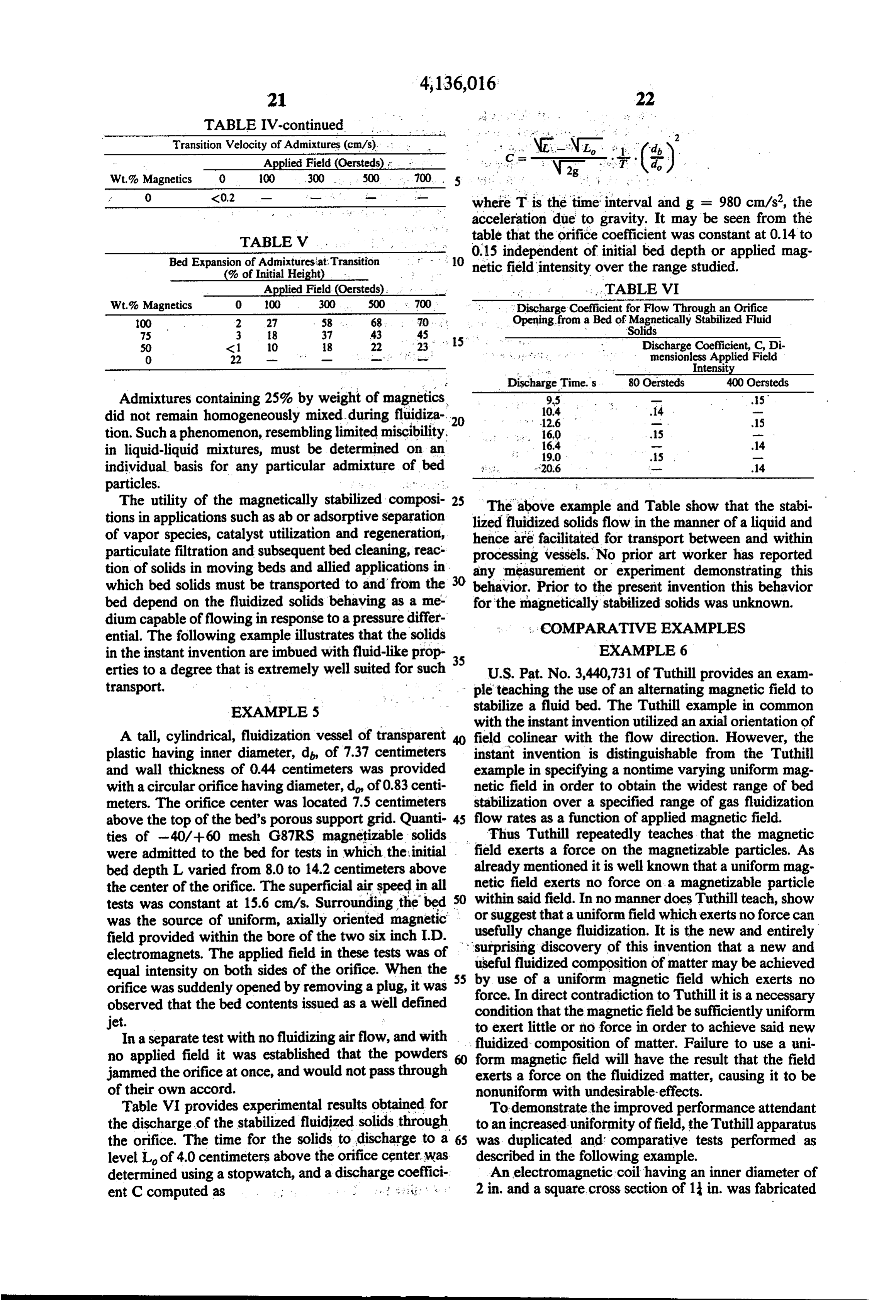
O <0.2 Wr - - - where T is the time interval and g = 980 cm/s, the acceleration due to gravity. It may be seen from the
TABLE V table that the orifice coefficient was constant at 0.14 to Bed Expansion of Admixtures at Transition 0.15 independent of initial bed depth or applied mag f : . . 10 netic field intensity over the range studied.
(% of Initial Height) . .
Applied Field (Oersteds). . . TABLE VI Wt.% Magnetics O 00 300 500 c. 700 Discharge Coefficient for Flow Through an Orifice 100 2 27 58 ... 68 O. : : Opening from a Bed of Magnetically Stabilized Fluid 75 3 8 37 43 4S ; 15 Solids SO <1 O 18 22 23 Discharge Coefficient, C, Di O 22 - " - - - -- - mensionless Applied Field Discharge Times 80 Oersteds 400 Oersteds
Admixtures containing 25% by weight of magnetics, 9.5 - .5 did not remain homogeneously mixed during fluidiza 20 10.4
tion. Such a phenomenon, resembling limited miscibility, ... 160 .. . .5 a in liquid-liquid mixtures, must be determined on an 6.4
individual basis for any particular admixture of bed ; :, -20.6 - w .14 particles. w
The utility of the magnetically stabilized composi- 25 The above example and Table show that the stabi tions in applications such as ab or adsorptive separation of vapor species, catalyst utilization and regeneration, lized hence fluidized solids flow in the manner of a liquid and are facilitated for transport between and within particulate filtration and subsequent bed cleaning, reac processing vessels. No prior art worker has reported tion of solids in moving beds and allied applications in any measurement or experiment demonstrating this which bed solids must be transported to and from the 30 behavior. Prior to the present invention this behavior bed depend on the fluidized solids behaving as a me for the magnetically stabilized solids was unknown. dium capable of flowing in response to a pressure differ ; : COMPARATIVE EXAMPLES ential. The following example illustrates that the solids in the instant invention are imbued with fluid-like prop 35 EXAMPLE 6 erties to a degree that is extremely well suited for such U.S. Pat. No. 3,440,731 of Tuthill provides an exam transport. - - ple teaching the use of an alternating magnetic field to EXAMPLES stabilize a fluid bed. The Tuthill example in common with the instant invention utilized an axial orientation of
A tall, cylindrical, fluidization vessel of transparent 40 field colinear with the flow direction. However, the plastic having inner diameter, d, of 7.37 centimeters instant invention is distinguishable from the Tuthill and wall thickness of 0.44 centimeters was provided example in specifying a nontime varying uniform mag with a circular orifice having diameter, d of 0.83 centi netic field in order to obtain the widest range of bed meters. The orifice center was located 7.5 centimeters stabilization over a specified range of gas fluidization above the top of the bed's porous support grid. Quanti- 45 flow rates as a function of applied magnetic field. ties of -40/+60 mesh G87RS magnetizable solids Thus Tuthill repeatedly teaches that the magnetic were admitted to the bed for tests in which the initial field exerts a force on the magnetizable particles. As bed depth L varied from 8.0 to 14.2 centimeters above already mentioned it is well known that a uniform mag the center of the orifice. The superficial air speed in all netic field exerts no force on a magnetizable particle tests was constant at 15.6 cm/s. Surrounding the bed 30 or within said field. In no manner does Tuthill teach, show was the source of uniform, axially oriented magnetic usefully suggest that a uniform field which exerts no force can field provided within the bore of the two six inch I.D. surprisingchange fluidization. It is the new and entirely discovery of this invention that a new and electromagnets. The applied field in these tests was of useful fluidized composition of matter may be achieved equal intensity on both sides of the orifice. When the 5 by use of a uniform magnetic field which exerts no orifice was suddenly opened by removing a plug, it was force. In direct contradiction to Tuthill it is a necessary observed that the bed contents issued as a well defined condition that the magnetic field be sufficiently uniform jet. to exert little or no force in order to achieve said new In a separate test with no fluidizing airflow, and with fluidized composition of matter. Failure to use a uni no applied field it was established that the powders so form magnetic field will have the result that the field jammed the orifice at once, and would not pass through exerts a force on the fluidized matter, causing it to be of their own accord. nonuniform with undesirable-effects. Table VI provides experimental results obtained for To demonstrate the improved performance attendant the discharge of the stabilized fluidized solids through to an increased uniformity offield, the Tuthill apparatus the orifice. The time for the solids to discharge to a 65 was duplicated and comparative tests performed as level Lof 4.0 centimeters above the orifice center was described in the following example.
determined using a stopwatch, and a discharge coeffici An electromagnetic coil having an inner diameter of ent C computed as ; : .. . . .. . . . . . . . . . 2 in. and a square cross section of 1 in. was fabricated
Page 18
of 14 gage copper wire. When supplied with 60 cycle The results of a series of tests that indicate the influ current of 1.25 amperes, 3.9 volts were measured across ence of field uniformity on bed stabilization is summa the magnet's terminals. The magnet resistance was 0.76 rized by Table VIII.
In the absence of an applied field the bed fluidized at ohms and thus the IR power dissipated by the magnet was 1.2 watts. A Hall probe positioned 9/16 inch above 5 a superficial velocity of 8.7 ft/s as evidenced by motion the top of the coil measured a field intensity of 34 gauss. of balls at the bed surface. At 9.2 ft/s the bed contents At the same position Tuthill reports a field intensity of exhibited circulatory motion, rising at the center and 365 gauss, or about ten times the value found here. It is descending at the walls. At 10.5 ft/s the bed slugged to well known that the field generated by a coil of a given a height of 10 mm. With further increases of flow rate conductor having a given geometry depends only on 10 the bed contents could be made to slug to any desired the power input. If it is taken as a fact from Tuthill's height within the column. The value of 10.5 ft/s was example, that his magnet also dissipated 1.2 watts, cor adopted as a reference velocity, with the last column of responding to 0.8 amperes of current and resistance of Table VII representing incremental increases in super 1.9 ohm, his field should be smaller. It appears that the ficial velocity associated with the application of the field intensity reported by Tuthill would require 10 15 magnetic field.
times the current or 100 times the power he reported. With the magnet positioned above the bed the field Most likely the Tuthill field intensity is overstated. nonuniformity was 165% as detailed in Tables VII and Notwithstanding the above variance, a duplicate of VIII. A comparative test at the nonuniformity of 51% the Tuthill bed was prepared comprising one hundred corresponded to positioning the magnet at the level of and ninety-two grams of in diameter carbon steel 20 the centerpoint of the bed. An additional test at nonuni balls charged to an open-topped cylindrical glass fluid formity of 11% utilized another magnet, one having a ization chamber having an inner diameter of 1 in. and six inch bore and four inch length.
a height of 24 inches. At the lower end of the column deferral In all cases, the application of magnetic field caused a the diameter was tapered and fitted with a gas inlet of of slugging to a higher value of gas throughput. reduced diameter. Near the bottom of the column and 25 In the tests described the bed contents were observed supported by the tapered section were several layers of to recirculate prior to the onset of bed slugging. Gener woven stainless steel mesh having about in. openings. ally this recirculation is undesirable in applications of The mesh layers were arranged with their grid axes in stabilized beds requiring a high degree of staging or non-orthogonal alignment to serve as a combination excellence of countercurrent contacting. It was sus support grid for the balls and as a distribution plate for 30 pected that the cause of recirculation was the low pres the fluidizing medium. As such this apparatus dupli sure drop of the support grid relative to the pressure cated the apparatus of Tuthill. drop f the bed. A grid of 100 mesh screen described in The height of the settled bed of balls extended for 2 the example below was substituted for the inch mesh inches above the topmost layer of mesh. of the Tuthill bed and cured the problem.
TABLE VI
NFLUENCE OF AC. FELDSPATAL UNIFORMITY ON SLUGGNG
OF BED OF IN. CARBON STEEL. SPHERES
Superficial Velocity, ft/s
Test
Reference
MeanGauss
of Field, 26.
Slugging
Motion Velocity Increment 4391-14 O -- 10.5 0.
4391-15 35 16S 12.0 1S 4391-19 36 51 - 13.4 2.9 3459-51 35 " . . 1 14.4 3.9 10 mm height.
Mean Fields (Maximum field in bed + Minimum field in bed)/2.
Nonuniformity of fields (Maximum field in bed - Minimum Field in bed) x 100/Mean Field.
(d) Corresponds to nonunifornity in example of Tuthill.
TABLE VI
MAGNETC FELD PARAMETERS
Magnetic Field, Oersteds
Distance of Magnet o Non Test Magnet Center over Grid, Magnet . Maximum Minimum Mean uniformity, Reference Identification Inches Current, Amperes in Bed in Bed in Bed % 4391-14 -- 0. (a) (a) (a) O 4391-15. 2 inch bore 4. 3 63(b) . 6(d) 35 16S .4391-19 2 inch bore 1. 45(c) 27(b)(c) 36 S1 3459-51 6inch bore 1. 58 37(c) 33(b)(d) 35 11 ignores laboratory background field of about 0.5 gauss,
(Red top surface.
Bedcenter.
Bed bottom.
The electromagnetic coil was supported coaxially Since Tuthill employed a magnetic source driven by with the fluidization column with the mid-plane of the an alternating current, the direction of field reversed coil at a height of 4 in above the top-most layer of 65 with time. If the bed of particles possess an appreciable mesh. remanence the reversal of field direction can cause the A rotameter fed by a regulated source of compressed particles to rotate or agitate in attempting to track the air was provided to measure the flow rate. field direction. The following example demonstrates the
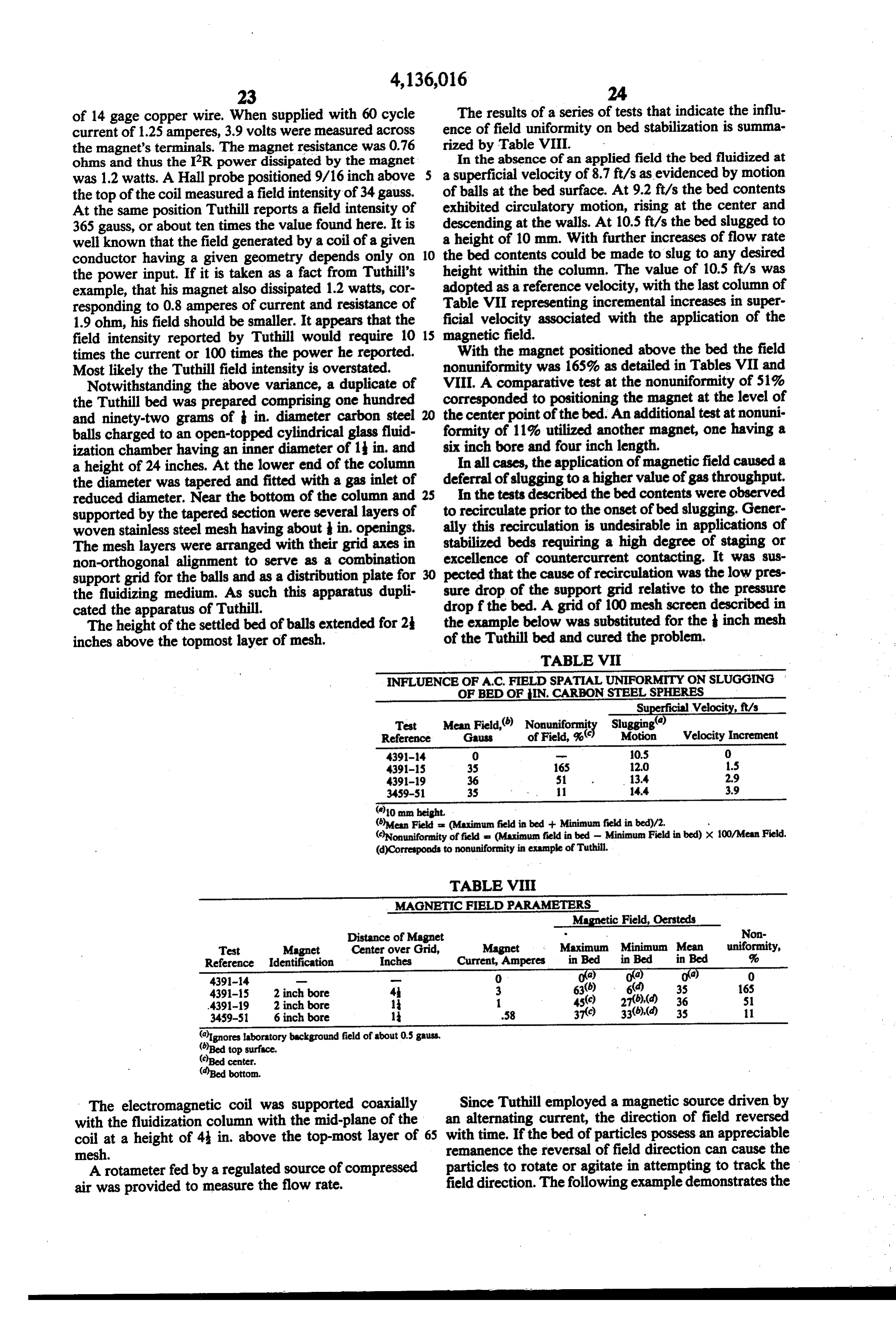
Page 19
adverse influence alternating magnetic field can exert moment (e.m.u./g), H is applied field (oersteds), R is on stability of such fluidized solids. equivalent spherical radius of the particle (cm) and f is Example 7 frequency (Hz). Table X comparing conditions of Ex amples 6 and 7 illustrates that the criterion predicts
The fluidization chamber of the example given previ 5 correctly the outcome of these tests. Thus, the criterion ously was modified by removing the coarse grid and is suggested to detireate the combinations of particle adding a grid of 100 mesh screen capable of supporting magnetic moment and size, and magnetic field intensity powders that are screened to -40/+60 mesh. A pack and frequency which permit bed stabilization to be ing of inch plastic spheres was provided upstream of obtained in the face of alternating field. Stability in the the mesh to insure a uniform approach flow. The first O race of alternating applied field is favored by large quadrant hysteresis loop for G87RS powder was deter particle size, high frequency, and small remanence. As mined using a vibrating sample magnetometer. The can be seen from the above Example, the use of alternat saturation moment was 13.8 e.m.u./g. at 3500 gauss and ing applied magnetic fields can be deleterious to the remanence was about 3 e.m.u./g. A 39 mm depth of the stability of fluidized magnetized solid particulates. G87RS powder was placed on the grid and a series of 15 . TABLE X tests performed using direct and then alternating cur rent to energize the 1" x 1' cross-section magnet STABILITY OF FLUDZED SOLIDS TO ALTER
NATING MAGNETICFELD
described in the previous example. The results of these Example 6 Example 7 tests are summarized in Table IX. Here the term "transi Bed Media Iron spheres Catalyst powder tion speed" is used with a special meaning in reference 20 Particle size, to the AC tests wherein although the term denotes the R., cm.
Remanent moment,
observation of surface bubbling the bed is not truly or c.m.u./g. 1S 3.0 fluidized (lifted). Field intensity,
TABLE IX Frequency, f. Hz 60 60 INFLUENCE OF ALTERNATING AND DIRECT 25 N (computed)
Prediction
Stable Unstable
CURRENT FIELD SOURCES ON SURFACE Observation Stable Unstable
BUBBLING OF A MAGNETIC BOWDER
HAVINGREMANENCE
Peak Field, Transition Velocity.cm/s
Gauss DC AC Example 3 has already illustrated the very adverse O 13.0 13.0- 30 influence that an appreciable transverse gradient offield 30 15.5 7.1 may exert on the ability of a bed of magnetizable parti 60 17.8 7.8 cles to be fluidized. In the following example, it is dem
120 22.4 10.0 onstrated that when the applied field is vertically ori 39 mm depth of -40/+60 mesh G37RS. ented it is preferable in the interest of achieving the s and AC sources both 20% non-uniform over the bed volume, 35 widest possible stable range of the bed at the lowest consumption of electrical power to utilize the most
From Table IX it may be seen that application of the uniform possible magnetic field.
direct current field increased the transition velocity of Example 8 the bed of powders while application of the alternating current field decreased the transition speed relative to 40 Various configurations of magnets, magnet position the value observed in the absence of field. Thus, alter relative to the vessel and magnet current were set up to nating field is undesirable in preparing the said stabi provide discrete levels of field nonuniformity at several lized compositions of matter. constant values of mean field applied over the volume The instant invention is distinguishable from the Tu of a bed of -40/+60 mesh G87RS solids having a thill art in that time steady magnetic fields are preferred 45 settled bed depth of 39 mm. The magnets were those in the instant invention. described in the previous examples. The bed was the 1 Ideally in a fluidized bed an individual particle of the inch inner diameter glass column.
bed may rotate with a minimum of frictional torque due The operating conditions and test results are given in to the negligible contact with neighboring particles. By Table XI where it may be seen that mean field was set considering the angular displacement of a bed particle 50 as 0, 40 ca 120, or 400 oersteds in any given test and, having remanent moment in response to the magnetic likewise, the variation of field over the volume of the torque set up by a reversing field, with rotation resisted bed in any one test was established as 136%, 17% or by particle inertia alone, a criterion may be obtained 4%. Transistion speed was established by noting for a indicating the range over which alternating field pro bed whose content had previously been aerated in the duces an appreciable rotation of the particle and hence 55 absence of applied field, the flow rate at which steady presumably tends to upset the stability of the bed. The bubbling was observed at the top surface after magnetic criterion may be stated as field had again been applied. The last column of Table XI lists the width of the stable range, measured in veloc > unstable ity units, between the normal fluidization speed of the N. bed and the speed at which bubble transition occurs. At <l stable where 5 aO H the low meanfield of 40 oersteds where the stable range N = - 8 TR f is very narrow, about 4 velocity units (cm/s), the preci sion of the data does not permit any conclusion regard ing the influence offield nonuniformity on transition.
The criterion applies for field cycle times that are 65 However, at the mean field of about 120 oersteds it is smaller than the duration of bed operation. Thus, direct seen that the field with 4% variation stabilizes twice as current beds, which have the greater stability, are not broad as nonbubbling range as the nonuniform 17% and described by the criterion. In the formula or is remanent 136% cases. The same striking behavior is exhibited in
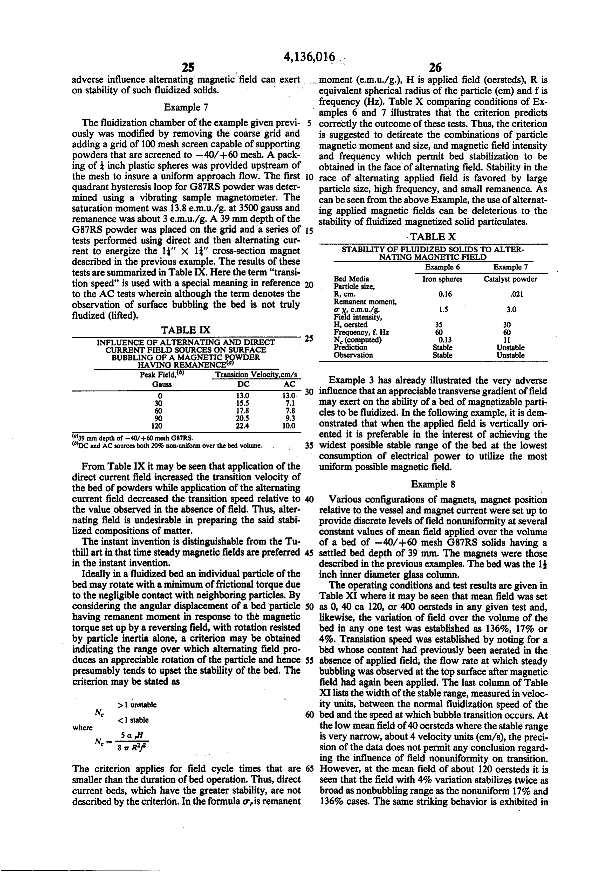
Page 20
the tests at 400 oersteds mean field in which stability ment with no relative motion between bed solids when over a range of width 29.1 cm/s was achieved at 4% the bed discharges.
spatial variation in applied field while 17% variation Twelve hundred and eighty five grams of 350 to 840 reduced the stable range to only 17.8 cm/s. microns G87RS catalyst was placed in a 7.5 centimeter In addition to the superior performance attendant to 5 transparent plastic vessel fitted with a porous disk dis use of uniform field it is noted that power consumption tributor. The dumped bed height was about 28.4 centi to operate an electromagnet source of field is vastly meters. Eight discharge ports were provided symmeti reduced. For example, referring to Table XI, for mean cally spaced around the vessel sidewall, each having field of 120 oersteds, the equivalent stable range is ob- diameter 0.64 centimeter with the center of each hole tained at 136% nonuniformity as at 17%, but the power 10 3.8 centimeter above the top of the distributor. A rotary consumption assuming the magnet's resistance was un- valve permitted opening the discharge ports simulta changed, was larger by the gar of the ratio of cur- neously.
rent. This computes to (25/3) or 69.4 times the power A portion of the normally black bed solids was consumption at 136% as at 17% nonuniformity of field. tagged with a surface coating of blue pigment particles, 15 Ultramarine 59-4933 of Cyanamid Company, and
TABLE XI
INFLUENCE OF AXAL D.C. FIELD AXIAL UNIFORMITY ON NSTION
TO BUBBLING FOR BED OF -40/-60 MESH G87RS
Magnet Current, Mean Field, Nonuniformity Superficial Velocity,cm/s Test No.9 Configuration Amperes Oersteds of Field, 2 Transition Stable Range 47:20 None 0.0 O 0 13.2 0.0 50:A TA 9.0 40 136 17.8 4.6 47:24 T/C 1.0 40 17 16.6 3.4 49.8 RMC 0.5 40 4. 17.3 4.1 50:C TMA 25.0 111 136 21.3 8. 47:25 T/C 3.0 120 17 21.9 8.7 49:D RMC 1.5 20 4. 30.8 17.6 50:E T/C 10.0 400 17 31.0 17.8 47:10 R/C 5.0 400 4. 42.3 29.1 T denotes 2 inch bore 14" x 1" cross-section toroidal electromgnet. R denotes two 6 inch bore electromagnets at 1 inch stic A denotes magnet center 4 inches above support grid. C denotes magnet center coincident with center of bed. Settled bed depth of 39 mm over 100 mesh grid.
Definitions are given in footnotes to Table VIII.
Throughout the foregoing the discussion has utilized placed in the bed in layers. In the settled bed the blue the artifice of a fluidization chamber operated in the colored layers varied from 0.80 to 1.0 centimeter in presence of a gravitational force field. It will be evident thickness with the bottom of the lowest layer located that the new composition of matter can be generated as 35 9.7 centimeters above the distributor and the remaining well in other force fields provided the flow of fluidizing layers spaced 5.0 centimeters apart from each other gas is in the direction opposing the external force field. with the uppermost layer forming the top of the bed. Thus the force field may be due to centrifugal forces of The field source was a 20 centimeter bore by 100 a rotating system, or for the electrical force on charged centimeter long electromagnet solenoid made up of 12 matter in an electrostatic field, or to dielectrophoretic 40 identical pancake modules each having thickness of 4.1 force of electrically polarized matter in an electrostatic centimeters and face to face separation of 7.0 centime field having a field gradient, or to forces caused by ters over the region occupied by the vessel. The applied presence of a magnetic field gradient, or to Lorentz field was uniform to within 2% over the test volume, force due to passage of a current at an angle to a mag- and in the test applied field intensity was constant at 400 netic field, or due to any other force field or to combina- 45 oersteds.
tions of the foregoing. In each instance the end result is With the field applied and the discharge ports closed, the achieving of a stable form of fluidized matter having a flow of air was admitted to the vessel. As minimum the thermodynamic analog properties, transport proper- fluidization speed was passed the bed expanded with ties and other properties inherent to the state of bulk further increase of flow rate and the colored bands were matter already described. 50 observed to rise with the bed. The flow rate was It is noted that while the instant invention has been brought to a superficial velocity of 30.5 cm/s. The inter defined in terms of a novel composition of matter, the faces between the colored layers and the bed remained process for obtaining said composition, as claimed be- sharply defined.
low, is also a part of the instant invention. Also the The rotary valve was actuated to suddenly open the composition of matter disclosed above may be arranged 55 eight discharge ports. The bed volume then suddenly throughout the contents of a bed or alternatively, if contracted due to reduction of air flow up the bed as a desired, at points or regions within a bed. It will be portion of the flow bypassed through the discharge understood that the term point denotes a localized re- ports. Then a slower process of bed movement contin gion which in all dimensions is large compared to the ued in which the solids descended and the colored lay spacing between particles and is small compared to any 60 ers were observed to move down the column as bed dimensions of the bed. solids discharged through the vessel sidewall openings. With the bed solids about half discharged the rotary
Example 9 valve was rapidly closed, the full upward flow of air
Example 5 demonstrated that the solids in the mag- resumed, and the bed observed to expand and accom netically stabilized fluidized bed will flow and dis- 65 modate the increased air throughout that once again charge through an orifice in the vessel sidewall. The was established.
purpose of this example is to demonstrate further that With the bed then quiescent in stable batch operation, movement of the solids may achieve piston displace- the colored layers could be examined at leisure. Inspec
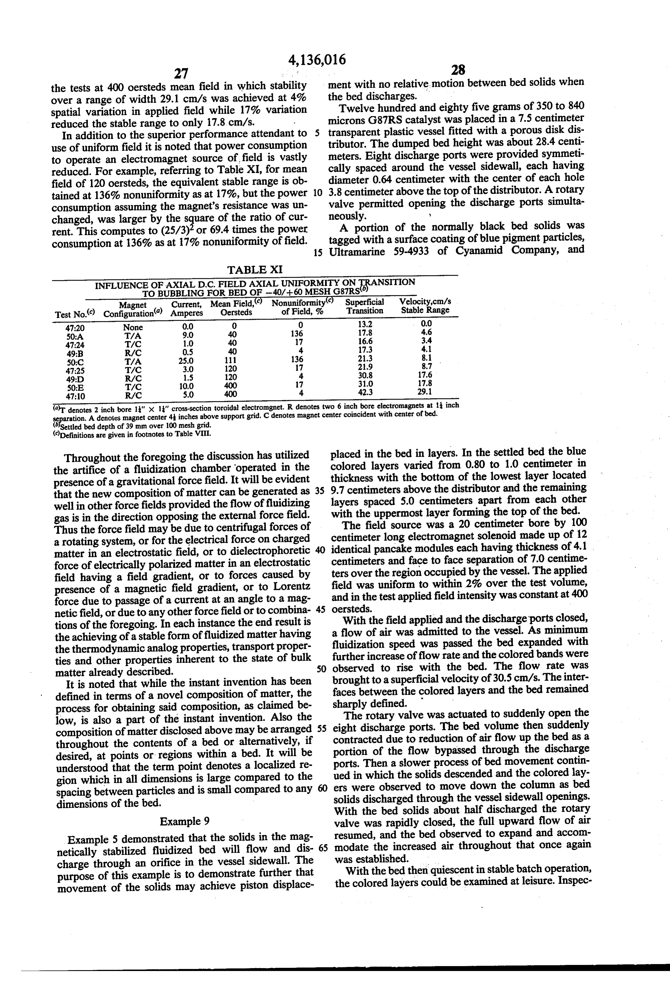
Page 21
tion of the layers illustrated they were free of distortion means in column. 2 of Table XII indicate the complete and that the bed was free of solids backmixing insofar as absence of bubbles in the fluidized medium. could be detected from the appearance at the bed side . . ." . . . . . . . . . . .TABLE XII surface and the bed top. There was no adherence of MAGNETCFIELD FLUCTUATION MEASUREMENTS solids to the wall and it was concluded the solids de- 5 IN FLUIDIZEDMAGNETZED MEDUM scended with uniform speed over the bed cross section. Hall Probe Measurements Sufficiently close to the discharge ports the flow, of H mean Hrms'/H mean course, cannot remain one dimensional in character but % State of Bed must flow sideways. is: 8 E: Inspection of the solids discharged from the ports 10 ; 0 (2) SIA: revealed the amounts to be closely equal and distributed : 8 quiescent in piles at nearly equal distances from the discharge 350 SE: ports. 309 0.6 light bubblin The rotary valve again was opened and the solids 242 1.0 moderate Sling permitted to discharge fully. Motion picture photo- 15 119 1.8 heavy bubbling
graphs were recorded of the test and verified the above 12 5.0 heavy SE description. rms is defined as the root mean square of the fluctuation signal. Example 10 values listed as zero in fact were somewhat less than the noise level after correct ing for measured noise, hence are neglected. The neglected values ranged from
The purpose of this example is to illustrate by mea 20 0.004 to 0.013 percent.
surement the absence of fluctuations of bed voidage in the stably fluidized magnetized bed of the present in Example 11 vention and the presence of fluctuations when the bed This example demonstrates the influence of particle
One hundred and sixty six grams of 20/+30 U.S. 25 size and bed mass on transition velocity. sieve G-87RS catalyst were placed in a 5 centimeter Monel The bed solids were various narrowly sieved sizes of I.D. glass vessel fitted with a porous disk distributor. A (ferromagnetically soft copper-nickel alloy) hav magnetic field of 569 oersted intensity was applied to ing specific gravity 8.45 and particle magnetization of 372 gauss at 5000 oersteds applied field. The transparent the bed. Nitrogen at ambient temperature and pressure plastic cylindrical fluidization vessel was 7.57 centime was passed upward at a superficial velocity of 51.4 cm/s 30 yielding an expanded bed height of about 15 centime ter inside diameter and fitted with a porous disk distrib utor. The fluidizing gas was air. The field source was ters. Minimum fluidization velocity previously was the 20 centimeter bore elecctromagnet described in found to be 23.5 cm/s as determined from the break point in a curve of measured values of pressure vs. flow through its9.hollow
Example This electromagnet was water cooled copper conductive windings.
rate. 35
A Hall effect gaussmeter probe (Bell Z OB4-3218) ficial velocity of thewhich
Results of tests in air length of the bed and super were determined at the transi was mounted above the vessel with its active elementin tion point are tabulated in Table XIII for various the middle of the bed of solids. The probe is a flat ended cylinder of 0.81 cm O.D. sensing the magnetic field amounts of solids in the vessel. At every test condition component normal to the flat end, i.e. the axial compo the bed was observed to fluidize smoothly, the bed top surface was flat and finely structured, and transition to nent of field in the vessel. The probe was connected to. bubbling occurred suddenly with a reproducibility of a Bell 620 gaussmeter, whose output was amplified by a
Tektronix AF 501. A custom low-pass filter having 5%It ormaylessbeofseen the superficial velocity. amplitude response down 50% at 70Hz to eliminate a 5. 45 increase of particlethatsizetransition velocity increases with KHz gaussmeter oscillator signal then fed a Disa 55D bed length. The transitionandspeed decreases with increase of of long bed tends to be 35 RMS unit operated with a 100 second averaging time, whose output was recorded on a Hewlett-Packard invariant of bed length.
The response and expansion of a bed having a con
Table XII presents the sequence of mean axial mag stant mass of Monel solids is given at Table XIV. As superficial velocity increases from its initial zero value netic field intensities applied to the bed, the fluctuation the bed remains of the field expressed as a percentage of the mean and restructuring of unchanged the bed top in length save for a minor surface. At the point of the visually observed state of the bed. Fluctuations minimum fluidization the bed begins to expand. Expan were absent within the precision of the measurement at sion is continuous as flow rate increases with the me mean field intensities of 350 oersted and greater, corre dium remaining quiescent in the stably fluidized sponding to a visually observed quiescent state of the 55 until the point of transition to bubbling occurs. state bed. The fluctuation level rises very sharply as the field break in the curve of bed length versus flow rate The fur is decreased through the bubble point, and more gradu nishes a definitive means of determining minimum fluid ally thereafter. The zero measured values of Hrms/H ization speed as an alternative to determining the break in the curve of pressure drop versus flow rate.
TABLE XIII
CORRESPONDING VALUES OF TRANSITION LENGTH
AND VELOCITY IN VARABLE MASS BEDS OF MONEL
His 5080 Oersteds
Particle Size, Microns
; Grams LT, cm, UT, cm/s LT, cm, UT, cm/s LT, cm UT, cm/s
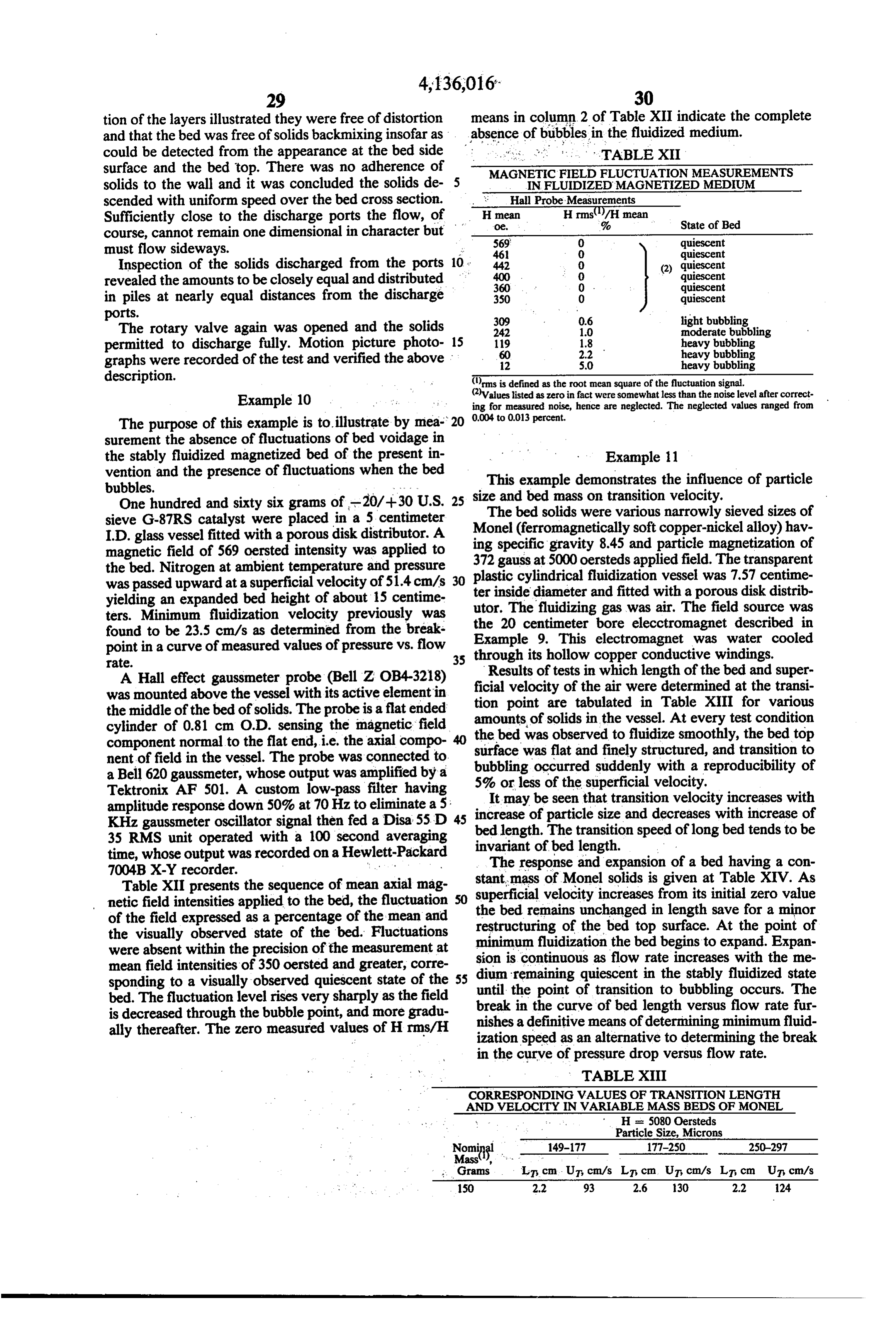
Page 22
TABLE XIII-continued
CORRESPONDING VALUES OF TRANSiTION LENGTH
AND VELOCITY EN VARABLE MASS BEDS OF MONEL
His 5080 Oersteds
Particle Size, Microns
NE 149-77 177-250 250-297 aSS
Grams LT, cm UT cm/s LT cm UT, cm/s LT cm Uy cm/s 400 no 5.6 90 S.0 15
1250 13.5 50 13.6 62 13.7 8S 1900 19.2 SO 19.9 64 200 85
Minimum bubbling speeds in absence of field increase with bed mass over the range given below:
Magnetometer measurement of the iron solids using the vibrating sample technique gives the values of mag
Table XV 20 netic moment listed in Table XV.
SENSEANSFENSSESSENESS
Superficial Velocity, Bed Length
TABLE XV
U., cm/s L., cm Comments STEELSPHERES(), (NAPPLIED FIELDS O 20.7 Unfluidized Applied Magnetic Magnetic Moment Magnetization 12 20.7 Unfluidized 25 E. H, Oersted o, emu/g ties 18 20.8 Unfluidized O 0.026 2.6 22 20.8 Unfluidized 16 668 67 28 20.8 Min. Fluidization 32 28 27 34 21.5 Stably Fluidized 48 iss 184 40 22.3 Stably Fluidized 64 25 242 51 24.4 Stably Fluidized 30 80 3.63 300 57 25.5 Stably Fluidized (4) 6.030 3.0
26.3 stably Fluidized
Transition Point sample mans of 0.3329 grams in cylindrical sample holder of about 3 mm I.D. Mass
Particleof size
micron. Surion
SM as 4 pormortinsorsedged fidg? 212 emu/s or 20,970 gauss.
with density p taken as 7.7 gram/cm.
Applied field 5000 oersteds 'Reduced from sooersted Vessel I.D. 7.57 centimeters. 35
The remanent magnetization of 2.6 to 3.0 gauss is small compared to the magnetization values at the ap
Example 12 plied field intensities, hence the material may be re
This example demonstrates that minimum fluidization garded as ferromagnetically soft in this working range. velocity of a magnetizable particle bed is constant and 40 Table XVI lists values of pressure drop across the unaffected by the presence of intensity of an applied whole bed length versus superficial flow rate at various magnetic field and that a higher velocity of gas intensities of applied magnetic field. FIG. 5 presents the throughput is required to cause the stably fluidized bed data plot for the field intensity of 48 oersteds. The to undergo transition from the quiescent state to a state breakpoint of the curve is taken as the point of minimum of bubbling or slugging motion. 45 fluidization. Values of minimum fluidization velocity A cylindrical fluidization vessel of 7.49 centimeter UFobtained in this manner are tabulated in the second inside diameter and 41 centimeter height over a micro column of Table XVII. There it may be seen that mini porous support grid is loaded with 3110 grams of C1018 mum fluidization speed has a sensibly constant value iron spheres supplied by Nuclear Metals Corporation. independent of applied field intensity. From column three of Table XVII it is seen that bed
The iron spheres are screened to the size range of 177 to 50 length is constant and unchanging below the point of 250 microns. The bed length with initially loaded solids minimum fluidization. The bed expands at flow rates is 15 centimeters. The magnetic field source is the pair greater of 6 inch bore electromagnets, each having length of 4 than minimum fluidization velocity, reaching inches and face to face separation of 1.5 inches. The the length given in the fifth column of Table XVII at magnetic field is oriented colinear with the bed flow 55 the point of transition to the bubbling state. The transi axis, with the center of the magnet pair at the center of tion mined to bubbling or slugging occurs suddenly as deter by visual observation. Steady surface bubbling gravity of the bed contents. The fluidizing gas is air.
A long straight glass tube of 6 mm O.D. and 4 mm for a minimum duration of about 30 seconds is taken as I.D. is inserted vertically into the bed to sense bed pres criterion for the transition, with the velocity at transi sure in the bed. The tube tip is positioned one centime- 60 tion denoted U.T. Values of UT are tabulated in the ter above the bed grid and a U-tube manometer con fourth column of Table XVII. At H of 64 and 72 oer nected to the other end of the tube. The bed is fluidized steds, transition was to slugging. in the bubbling regime in the absence of field, then FIG. 6 presents the diagram that results from plotting collapsed by stopping the gas flow before the beginning 65 UMF and UT versus applied field. The magnetically of a test sequence. The magnetic field is applied in the stabilized state of fluidized solids is defined by the re absence of flow, and pressure measured in response to gion between the curves of UF and and UT. This re increases in flow rate at the constant magnetic field gion provides a broad operating range in which the setting. medium is fluidized yet quiescent and free of bubbles or
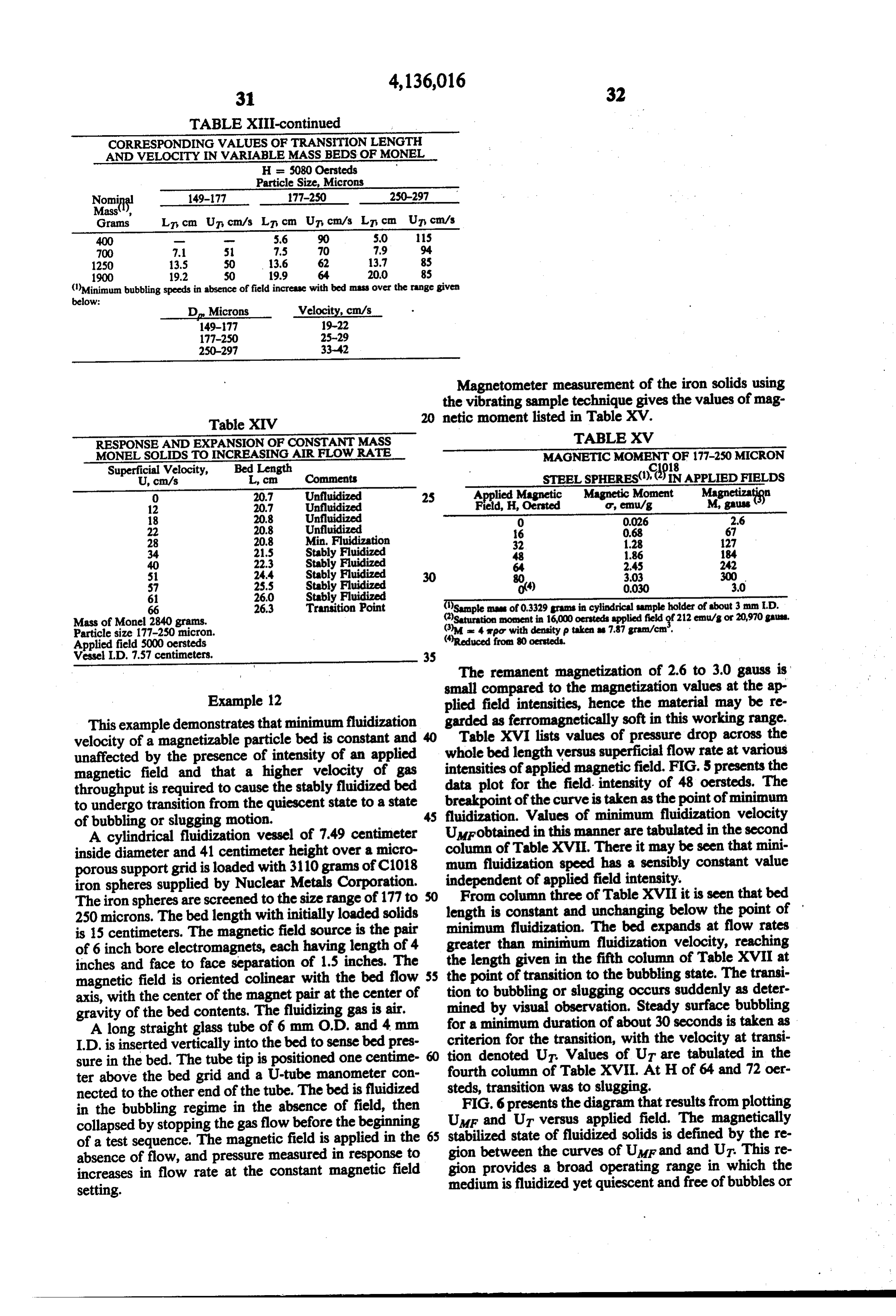
Page 23
solids backmixing. The bed medium in this region is process and the properties of the medium thereby gen facilitated for transport, e.g. into or out of the contain-. erated are totally unexpected and surprising.
TABLE XVII
BEHAVOR SUMMARIZED FOR THE MAGNETIZED BED
OF STEEL SPHERES (177-250 MICRONS)
Applied Field Minimum Fluidization Bed Length. At Transition Bed Length. At AP
H, Oersteds Velocity, UMF, cm/s Un, Lim, cm Velocity, UT, cm/s Transition, LT, cm W/A
O 13.5 15.0 13.5 5.0 0.91
64 S.0 15.0 68.3 8.0 1.02
At applied field of 80 oersteds the bed medium entrains as a plug moving up the vessel column at a gas throughput less than transition.
ing vessel EXAMPLE 13 TABLE XVI Ammonia catalyst of 3 to 6 mm. particle size was INFLUENCE OF FLOW RATE AND APPLIED FIELD crushed and sieved to U.S. mesh -20/-30. This cata INTENSITY ON PRESSURE OROPFOR SY 8F 20 lyst was previously magnetized in an applied field of ARTHROUGH ABEDOFIRON SPHERES(). 5000 oersteds. Due to its remanent magnetization the Flow Rate, U - Applied Field intensity, Oesteds material had the texture of wet sand, noticeable when cm/s O 16 32 48 64 72 pouring or screening.
; ; ; ; ; A quantity of 1280 grams was added to a fluidization 73 24 2. 24 24 22 23 25 vessel having inside diameter of 7.33 cm. The depth of 3: solids over the fitted porous distributor was 17.8 cm. 67 6 3 2 5i 5.4 5. In the absence of applied field as air flow was in 17.9 4.6 4.6 4.3 5.1 5.7 5.6 creased the bed of solids was observed to develop void
age layers of separation in the upper one-third of the 30 bed at a superficial velocity of 10.3 cm/s. Pressure drop : 6 : . . . through the bed increased smoothly with increase of 52 - 53 5.4 S.S superficial velocity until at 38.3 cm/s a spout formed in 8 - - s2 : the bed and the pressure drop decreased from about 6.4 cm. of dibutylphthalate (DBP) to 2.9 cm. The spout had
Pressure units are centimeters of mercury, extrapolated to support grid surface 35 formed along the length of the 6mm O.D. by 4mm I.D. ised on linear change with distance.
c1018 steel 177-250 microns. glass tube used as the pressure probe that was inserted at a 9 cm. depth within the bed. Thus, these solids failed to
The final column of Table XVII tabulates the plateau fluidize properly in the absence of applied field. value of pressure drop normalized by the ratio of bed When uniform, axially oriented magnetic field of 40 mass W to bed cross section area A; this quantity theo oersteds was applied the measured pressure drop in retically equals unity when expressed in dimensionally creased smoothly with increase of air flow rate up to a consistent units. The experimental values are in reason superficial velocity of 42.7 cm/s. A further increase of able agreement with the theoretical expectation and superficial velocity to 46.6 cm/s then caused a spout to verify the existence of the fluidized state of the bed in form adjacent to the probe and the measured pressure both the stabilized and bubbling regimes, i.e. regions in drop decreased by about 47%. Again the bed structure which velocity U is less than and greater than UT, re deteriorated and lead to bypassing of the gas stream. spectively. Finally, with applied field of 80 oersteds and the Sonoliker, R. L. et al., Indian Journal of Technology, probe tip located about 5 mm. above the support grid, 10, 377 (1972) reported observations of fluidized iron the bed retained its structural integrity throughout a test powders subjected to an axially oriented applied mag 50 sequence in which superficial velocity ranged up to netic field. In particular in Table I of Sonoliker et al., 100.4 cm/s. Pressure drop initially increased linearly experimental results are given for the minimum fluidiza with superficial velocity, then plateaued at 25.6 cm. tion velocity of iron particles, including results for par DBP. The break in the curve of pressure drop vs. super ticles of 244 microns diameter, hence comparable to the ficial velocity defined a point of minimum fluidization size range studied here. The values of minimum fluidiza 55 of 40.0 cm/s. The bed length was constant at 17.8 cm. tion velocity in Sonoliker et al increase exponentally up to the point of minimum fluidization, then expanded with applied field intensity. This is in marked contrast to 24.0 cm. at the said maximum flow rate of 100.4 cm/s. to the sensibly constant value of minimum fluidization The bed remained free of bubbles or agitation at all flow velocity characterizing the instant invention and illus rates studied. The test was repeated and displayed the trated by values in column two of Table XVII below. It similar behavior with maximum superficial velocity is possible that Sonoliker atal observed transition veloc reacing 115 cm/s, ity UT and identified it as minimum fluidization speed Magnetic moment of this ammonia catalyst is given in UMF. Accordingly, Sonoliker et al might have passed Table XVIII. The amount of 0.03 emu/g at zero applied through the stabilized region in a transitory manner in field pertains to a powder sample of the -20/-30 mesh their experiments. In any event it is clear that Sonoliker 65 material that had previously been subjected to 5000 et al provide no teaching of the existence of a stably Oersteds applied field. The low moment indicates the fluidized region as instantly claimed. In view of the sample particles were nearly randomly oriented since report of Sonoliker et at the performance in the instant the remanent magnetization is large for an undisturbed
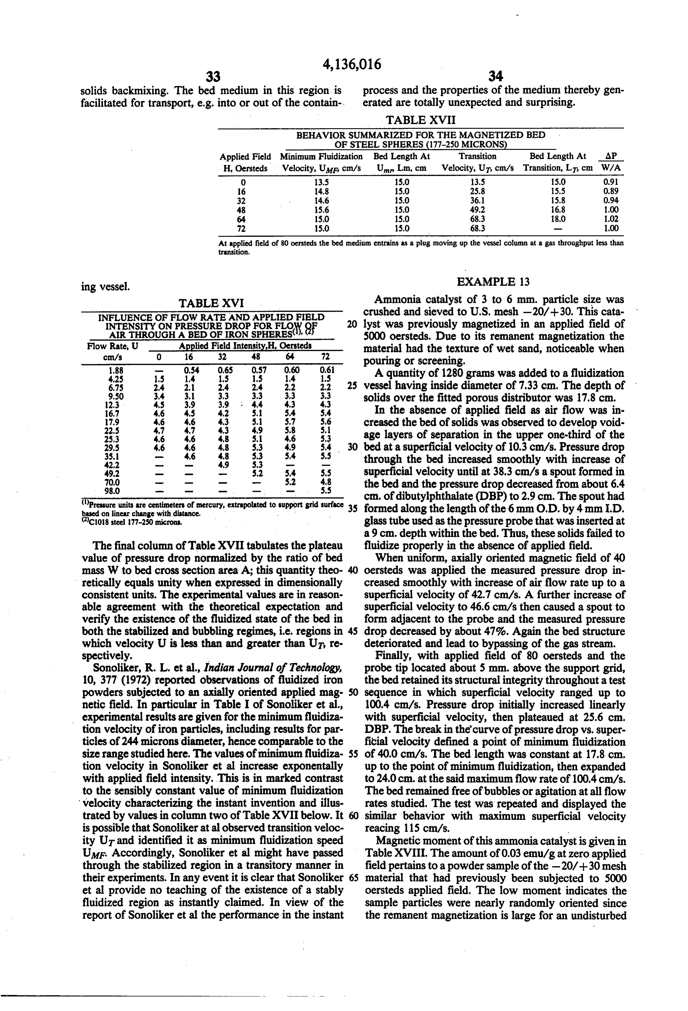
Page 24
sample, i.e., 18.4 enu/g after exposure to applied field observation of initial bubbling and motion in the bed intensity of 16,000 oersteds. coincide with the first detectable fluctuation of pressure
TABLE XVII
drop (pressure difference).
TABLE XIX
PRESSURE DROP, PRESSURE FLUCTUATIONS, AND BED LENGTH
CHANGE OF AIR FLUIDIZED C1018 STEELSPHERES OF 177
250 MICRON DIAMETERIN 48 OERSTED APPLIED FIELD
cm/s cm H2O cm H2O AL, cm the solids Bubbles or Motion 5.6 19, 0 0 Settled No 8.5 34.8 0. O Settled No 12.7 54.0 0 O Settled No 15.2 51.6 O 0.5 Stably Fluidized No 19.8 55.8 O 1.3 Stably Fluidized No 25.4 - 56.5 O 2.0 Stably Fluidized No 31.7 56.6 0.05 2.7 Unstably Fluidized Yes 40.9 S1.0 3.0 3.5 Unstably Fluidized Yes 56.5 53.0 3.0 3.5 Unstably Fluidized Yes
MAGNETIC MOMENT OF AMMONIA CATALYST TABLE XX Applied Field H., re. Magnetic Moment emu/g DISTINGUISHABLE O 0.03 20 STATES OF THE PARTICULATESOLIDS 40 1.58 State Pressure drop Bed Length 80 3.26 of increase increase Pressure 5,000 144 Solids with flow with flow Fluctuates 160 Settled Yes No No
25 Unstably Fluidized No Yes Yes
EXAMPLE 1.4 As can be seen from the above examples and descrip
This example illustrates that fluctuations of gas pres tion of the invention, the present invention provides a sure distinguish the bubbling state of magnetized, fluid means for conducting a fluidization process at a wide ized solids from the stably fluidized state. In the stably 30 range of flow rates before the bubble transition point is fluidized state fluctuations are not detected. reached. For example, as discussed above, it has been Two thousand nine hundred and seventy grams of able found that the larger the magnetization M of the fluidiz 177-250 micron spherical particles of C1018 steel de glomeration, and magnetizible particles up to the point of ag scribed in Example 13 were placed in a fluidization Urup to whichthethehigher will be the transition velocity stably fluidized bed may be operated vessel having inside diameter of 7.32 centimeters. The 35 without bubbling and time-varying fluctuation, all other vessel was fitted with a pressure tap in the sidewall at a point 4 centimeters above the porous support grid. The variables being equal. It will be recognized that in prac pressure tap contained a wire mesh screen that pre ticing the invention, it is the intent to operate the pro vented particles from leaving the vessel. One side of a 40 cess in the stable, non-fluctuation manner wherein the U-tube manometer containing water was connected to stably fluidized bed is bubble-free. Accordingly, the size, the tap and the other end of the manometer kept open to of bubbles in the stabilized fluidized media, if they do the atmosphere as was the top of the fluidization vessel. exist, will be about no larger than the spacing between particles and consequently do not cause time-varying
Uniform, axially oriented magnetic field of 48 oersteds fluctuations of the pressure difference through the fluid intensity was applied to the solids using the pair of six 45 ized bed over a finite period of time, e.g., 10 seconds, inch bore electromagnets. Increasing rates of steady air flow were admitted to the vessel to obtain measurement fluidization. second time interval during continuous preferably a 100 of pressure drop AP read as difference in height of As earlier indicated, the fluidization process of the water in the manometer legs. When the bed became present invention is useful in many applications hereto stably fluidized, its length gradually expanded with increased gas flow. Observation was also made of pres 50 fore used in the fluidization art. Of particular impor tance are the petroleum processes such as hydrofining, sure drop fluctuation EAP, if any, and presence or hydrocracking, absence of visible bubbling or motion in the fluidized ing and catalytichydrodesulfurization, catalytic crack medium. The fluctuations in pressure drop represent typical hydrocarbon conversion process summarizes reforming. The Table XXI conditions values detected over about a ten second interval. The observed values of pressure drop, pressure drop fluctua 55 effective in the present invention. The feedstocks suitable for conversion in accordance tions, bed length and other parameters, are listed in with the invention include any of the well-known feeds Table XX.
From the data in Table XIX it may be seen that the conventionally employed in hydrocarbon conversion processes. Usually, they will be petroleum derived, stably fluidized state is clearly distinguishable from the although other sources such as shale oil and coal are not settled state (fixed bed state) as well as from the unsta to be excluded. Typical of such feeds are heavy and bly fluidized state. Thus, only in the stably fluidized light virgin gas oils, state is pressure drop invariant of flow rate, and bed oils, middle distillates,coker gas oils, steam-cracked gas steam-cracked naphthas, coker length increasing with an increase of flow rate, while pressure fluctuations are absent. Comparative behavior 65 naphthas, cycle oils, deasphalted residua, etc. of the states is summarized in Table XX.
It is noted that in the fluidized states the constant
GENERAL
value of average pressure drop indicates the solids in the tained from a magnetometer whenM aofgiven Generally, the magnetization a particle as ob magnetizing vessel were supported entirely by fluid forces. Visual
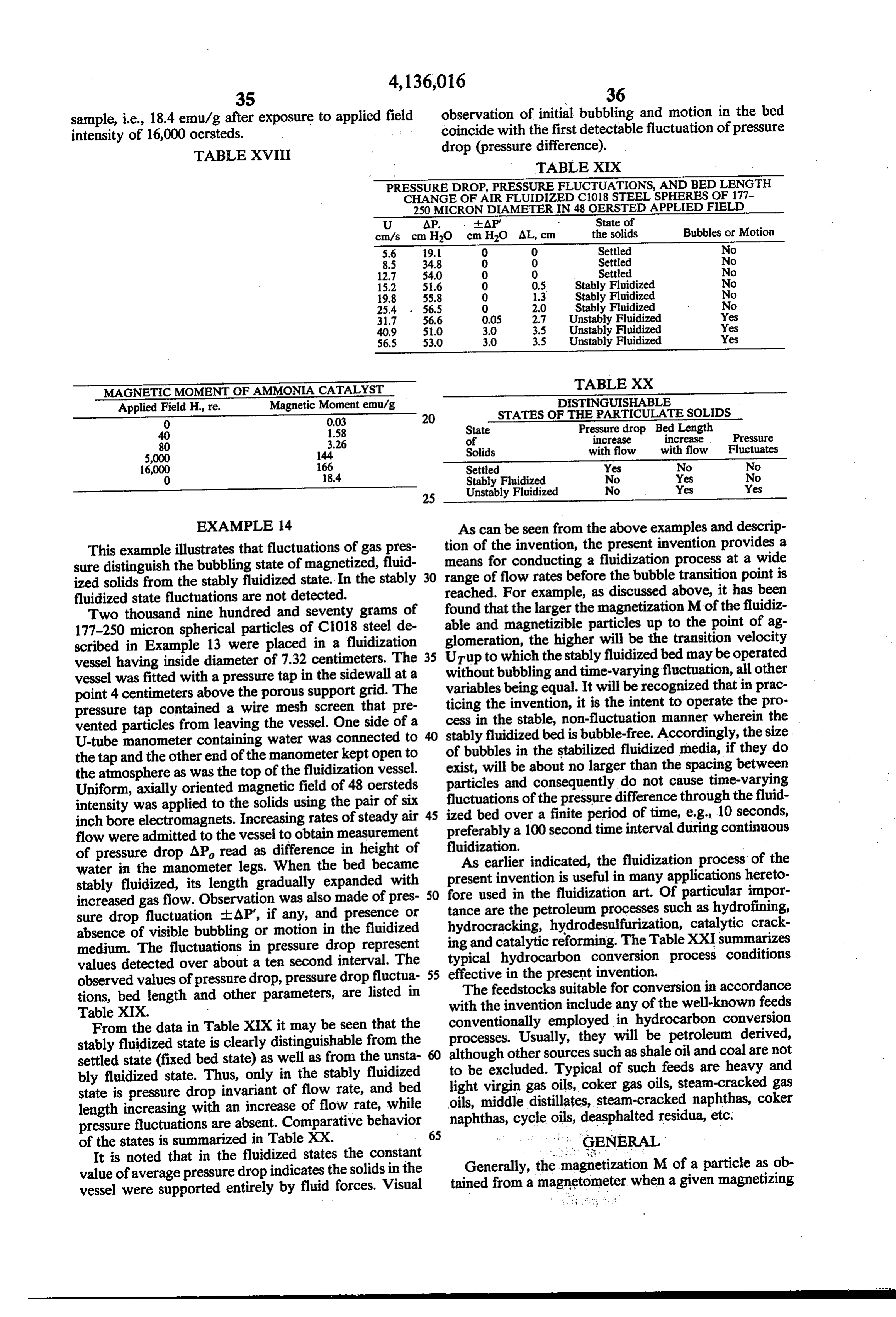
Page 25
field His applied will not provide a value which is the same as the magnetization of the particle in response to (4) the same intensity of magnetic field in the fluidized bed Kn =---
to be used in accordance with the teachings of the pres ent invention. 5 then from (2) Knequals the quantity M/Ha-H) i.e. The purpose of the following is to indicate a method for determining the magnetization M of a typical parti Kn = M/(H-H) (5) cle in a bed from those values obtained from a magne tometer. Generally, this will require a calculation since Thus, on the graph of M. vs. He straight lines of slope the effective field that a bed particle is subjected to 10 K intersecting the measured curve and the Ha axis depends on the applied field, the bed geometry, the relate corresponding values of M and H. Accordingly particle geometry, the bed voidage and particle magnet a graph may be constructed of M. vs. H. For example, ization. A general expression has been derived to relate when the sample is contained in a spherical cavity d = these quantities based on the classical approximation of , Kn is infinite, and H equals H. For a long sample the Lorentz cavity that is employed in analogous physi- 15 such that d = 0, Kn is negative and His less than Hs cal problems such as the polarization of dielectric mole i.e. the field magnetizing a particle of the sample is greater than the field applied to the sample.
cules.
Additionally, for a process bed, a constant K may be
H = H + M, (d+ (1-6) (di-) (1) defined as follows:
His the applied magnetic field as measured in the ab- 20 6 sence of the particles, He the magnetic field within a K = (1 - a D- (6) particle, M the particle magnetization, d. the particle demagnetization coefficient, ethe voidage in the parti It may also be seen from Eq. (2) that a line of slope - cle bed, and d the bed demagnetization coefficient. The 25 Kpassing through a point Ha on the horizontal axis of term - is due to the magnetizing influence of a (vir the graph of Mvs. Hintersects the curve on the graph tual) sphere surrounding the bed particle, at a value of Mgiving the particle magnetization in the The expression above applies as well to a sample of bed. Thus, the particle magnetization M in a process particles such as used in a magnetometer measurement. bed has been related to the field Happlied to the pro In that case d is the demagnetization coefficient d. 30 cess bed.
corresponding to shape of the cavity in the sample The relationship of Eq. (1) is an approximation more holder. likely to be accurate for beds having high voidage than Magnetometer measurement produces a graph of M for very densely packed samples.
vs. H. Using the above equation and known values of It is to be understood that the term "applied magnetic ded to Mand Haa corresponding value of H may be 35 field' used throughout the specification and claims computed. When the value of His small its value found refers to an empty vessel applied magnetic field.
TABLE XXI
Reaction Conditions
Principal Conversion Temperature Pressure Feed Rate Hydrogen Rate
Desired F. psig V/VMHr. scf/Bb
Hydrofining 500-800 50-2000 0.1-100 500-10,000
Hydrocracking 4S0-850 200-2000 0.1-100 500-10,000
Catalytic Cracking 700-1000 OSO 0.1-200 O
Catalytic Reforming 800-1000 S0-1000 O,1-200 500-10,000
It will be understood by those skilled in the art that various modifications of the present invention as de in this manner is determined by a difference between scribed in the foregoing examples may be employed without departing from the scope of the invention.
large numbers, hence is subject to cumulative errors, so Many variations and modifications thereof will be ap Accordingly, a modified approach is useful as described parent to those skilled in the art and can be made with in the following. .
Thus it is useful to define a reference quantity H, out departing from the spirit and scope of the invention herein described.
representing the calculated field in a spherical cavity at What is claimed is:
the location of the particle. It is imagined that the mag netization of surrounding particles is unchanged when 1. Afluidized hydrocarbon conversion process which comprises:
the said particle is removed. (a) subjecting a fluidized bed comprised of magnetiz H = H, - M. (1-6) (di-) . (2) able, fluidizable composite particles which have catalytic activity for hydrocarbon conversion and
Combining the two expression gives an alternate rela- 60 which contain2 to 40 volume 9% ferro- or ferrimag tionship for H in which His eliminated. netic material to a nontime varying and substan tially uniform applied magnetic field having a sub
H = H + Ma (3) stantial component along the direction of gravity such that said composite particles have a compo
This expression is recognized to give H, as the change 65 nent of magnetization along the direction of grav of field in passing from the inside of a particle to the ity, and outside of the particle. (b) passing a fluidizing gaseous medium comprising a Denoting K as the following constant vaporized hydrocarbon feedstock upwardly
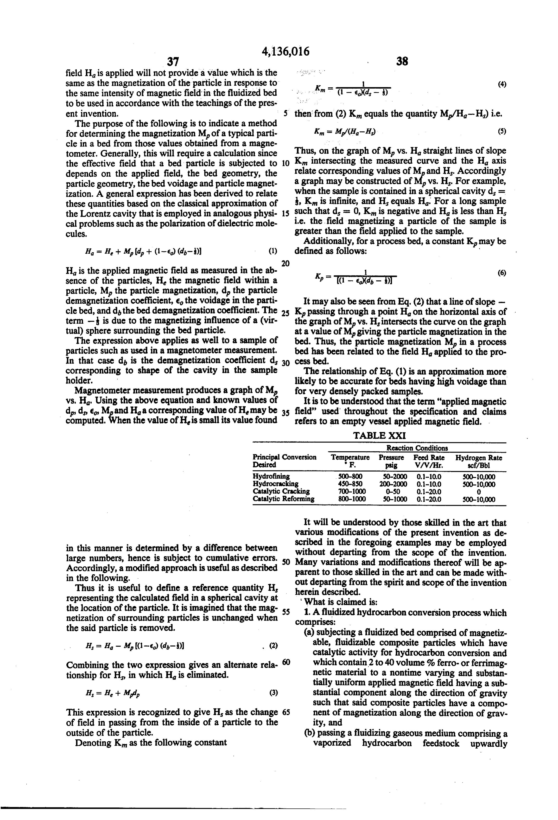
Page 26
through said bed at a superficial gas velocity rang posite particles are catalytically active for the catalytic ing between: desulfurization of said feedstock. (i) at least 10% greater than the normal minimum said4. bed The process of claim 3 wherein at least a portion of is subjected to a substantially uniform applied superficial gas velocity required to fluidize the bed in the absence of said applied magnetic field; and , magnetic field of at least 100 oersteds oriented axially to (ii) less than the superficial gas velocity required to the flow of gas in the fluidized bed zone and wherein cause time-varying fluctuations of pressure differ said magnetizable, fluidizable composite particles have ence through said bed for a 0.1 to 1 second time a magnetization 5. The process of at least 150 gauss.
of claim 1 wherein said fluidized bed is interval during continuous fluidization in the pres 10 at a temperature of 800-1100 F. and said magnetizable, ence of said applied magnetic field.
2. The process of claim 1 wherein said fluidizing fluidizable composite particles are catalytically active gaseous medium includes hydrogen. for the catalytic reforming of said feedstock. 6. The process of claim 1 wherein the uppermost 3. The process of claim 1 wherein said fluidized bed is 20-40% at a temperature of 500-800F, said fluidizing gaseous region or zone of the bed is stabilized by the medium comprises a vaporized petroleum feedstock 15 applied magnetic field. . . k is .
and hydrogen and said magnetizable, fluidizable com
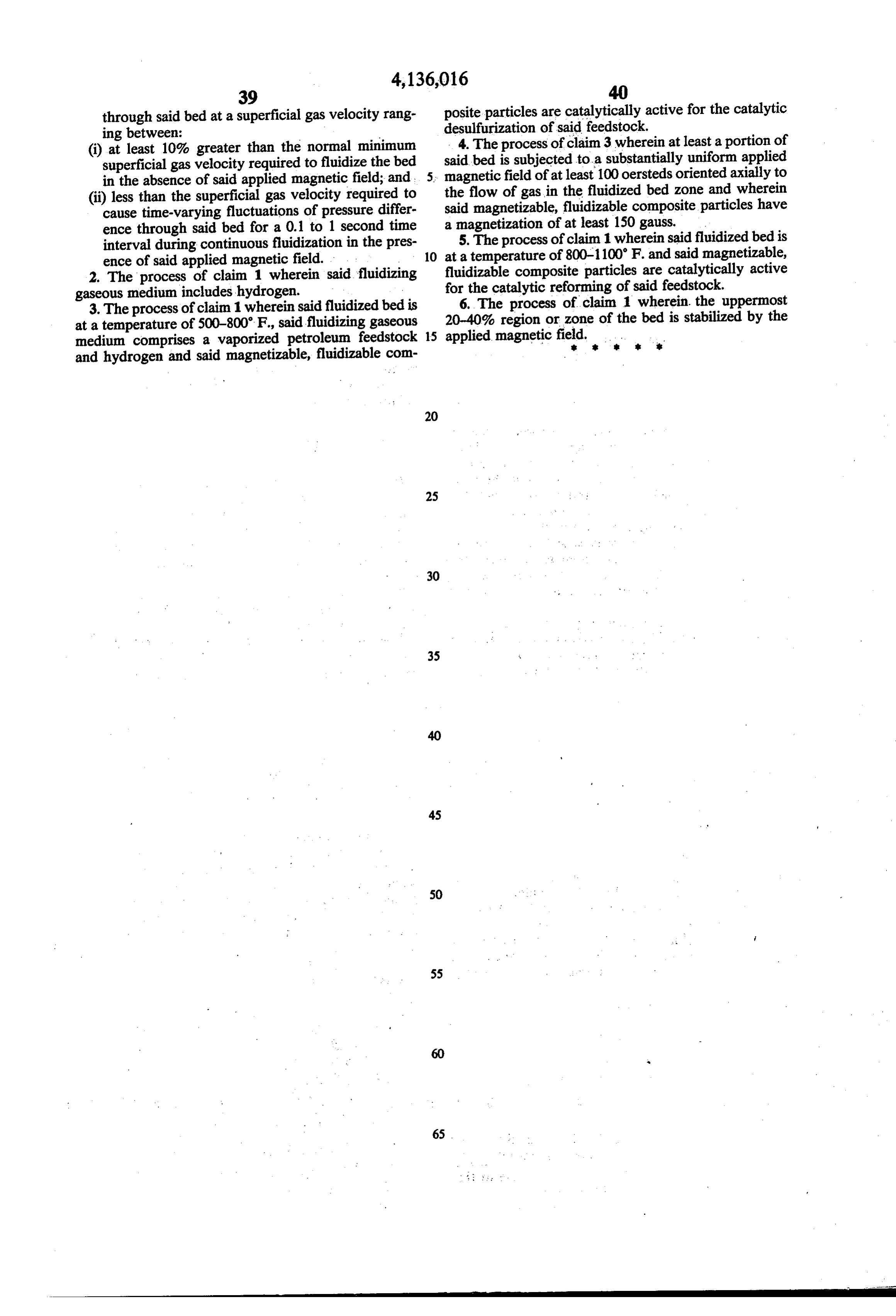
Provenance
- Collection
- Cited prior art
- Original PDF
- patentimages.storage.googleapis.com →
- Filed
- 1978-01-03
- Pages
- 26
- Method
- pdftotext (the PDF's own text layer) + pdftoppm 300dpi page scans
- Source
- Google Patents bibliographic record
- Granted
- 1979-01-23
- Inventors
- Ronald E. Rosensweig; Exxon Research and Engineering Co
- Transcribed from
- patentimages.storage.googleapis.com →