patent · US5641585
Miniature ceramic fuel cell
24 June 1997
Page 1 — bibliographic record
United States Patent 19 11 Patent Number: 5,641,585 Lessing et al. 45 Date of Patent: Jun. 24, 1997 54 MINATURE CERAMC FUEL CELL OTHER PUBLICATIONS 75 Inventors: Paul A. Lessing; Anthony C. International Solar Energy Intelligence Report, Jul. 11, Zuppero, both of Idaho Falls, Id. 1994.
Mechanical Engineering-CIME, Sep.1994.
73 Assignee: Lockheed Idaho Technologies "Developing New Miniature Energy Systems” Mechanical Company, Idaho Falls, Id. Engineering-CIME, vol. 116, No. 9, p. 82 (1994) Sep.). 21 Appl. No.: 408,761 Primary Examiner-John S. Maples Attorney, Agent, or Firm-Thorpe North & Western
(51) Int. Cl. ... H10M 8/04 - 52 U.S. Cl. .............................. 926,429.2042934. A miniature power source assembly capable of providing 58 Field fs rch O. 9 429/26. 24, 34 portable electricity is provided. A preferred embodiment of led O SeaCl .................................. 429.20 13 the power source assembly employing a fuel tank, fuel pump 9 and control, air pump, heat management system, power 56) chamber, power conditioning and power storage. The power References Cited chamber utilizes a ceramic fuel cell to produce the electric
4,650,727 3/1987 Vanderburgh et al. ............. 429/26X NE EE a chemical combustion of 5,342,703 8/1994 Kawasaki et al. ........................ 293 hydrog p 5,364,711 11/1994 Yamada et al. .......................... 429/15 5,470,670 11/1995 Yasumoto et al. .................... 429/26X 52 Claims, 11 Drawing Sheets
2 </ a2<
757 7 2 FUEL
FUEL
EXHAUST 1436 14 Rise ss 90
Page 2
Drawing sheet — no readable text.
Page 3
FUEL PUMP
CONTROL
HEA
MANAGEMENT
SYSTEM
HOT HOT FUEL AND
EXHAUST AIR OUT
CHAMBER
ELECTRICITY
OUT
ONDITIONING
ELECTRICITY
OUT
STORAGE
ELECTRICITY OUT
ON DEMAND
Fig. 2
Page 4
Drawing sheet — no readable text.
Page 5
Drawing sheet — no readable text.
Page 6
Drawing sheet — no readable text.
Page 7
Drawing sheet — no readable text.
Page 8
Drawing sheet — no readable text.
Page 9
Drawing sheet — no readable text.
Page 10
Drawing sheet — no readable text.
Page 11
Drawing sheet — no readable text.
Page 12
Drawing sheet — no readable text.

Page 13
MINATURE CERAMC FUEL CELL The disadvantage of discharge is exhibited by batteries CONTRACTUAL ORIGIN OF THE INVENTION using both dry cells and wet cells. Although some progress has been made in terms of battery life, charging time, and
The United States Government has rights in this invention shelf life, nevertheless most batteries will eventually be disclosed under contract number DE-AC07-94D13223 with discarded. Single use batteries are discarded when they Lockheed Idaho Technologies Company. become discharged. Rechargeable batteries have an advan BACKGROUND tage over disposable batteries in that they can be recharged and used again. The number of times arechargeable battery 1. Field of the Invention may be discharged and recharged is typically limited, This invention relates generally to fuel cells for providing 10 however, and eventually even rechargeable batteries will portable electricity. More specifically, this invention relates require disposal.
to miniature solid oxide fuel cells which are employed to The disadvantages and limitation of supplying power via provide power, typically in the form of direct current batteries, particularly with regard to large applications has electricity, to portable devices such as cellular phones, lead to attempts to develop alternative portable power sup notebook computer, and medical devices. 15 plies. One such alternative is the ceramic fuel cell. Ceramic 2. Background Art fuel cells utilize an electrochemical combustion of hydrogen A commonly employed method for providing electricity to produce direct current electricity. The hydrogen is typi to portable devices is to utilize a battery or batteries. cally derived from a hydrocarbon fuel, alcohol, or coal. Batteries are used in a range of devices from flashlights to Ceramic fuel cells are also commonly known as solid oxide cellular phones. Batteries may be single use or rechargeable. 20 fuel cells due to the predominant use of oxides as the Problems such as discharge have led to attempts to develop electrolyte.
replaceable power sources which would utilize a fuel to Solid oxide fuel cells have enjoyed some success, how create electricity. ever they are also possessed of a number of characteristics Single use batteries are probably the most commonly used which make them unsuitable to provide portable power to battery today. Single use batteries employ a dry cellor series 25 devices such as cellular phones, notebook computers, and of dry cells. Typically each cell produces 1.5 volts. The cells medical instruments. For example, prior art solid oxide fuel are connected in series to achieve the desired voltage. The cells are typically large and somewhat cumbersome. The associated current, and thus the total electrical energy large size of the typical prior art solid oxide fuel cell does not available, is dependent on the size of the cell. lend itself to use in small devices. A typical dry cell well known in the art would employ a 30 In addition, the high operating temperatures at which zinc coated metal container which would enclose all of the solid oxide fuel cells operate make them seemingly unsuit chemical ingredients and which would also serve as the able for incorporation in handheld devices. Further, the time negative electrode. The positive electrode would consist of interval required for a solid oxide fuel cell to begin produc a carbon rod. A paste of ammonium chloride, Zinc chloride, 35 ing direct current electricity is on the order of hours. Clearly and water would serve as the electrolyte. such a lengthy start up time is annoying at best in use with The positive terminal or anode of such a cell would be devices designed for convenience such as cellular phones surrounded with a thin layer of powdered carbon and and notebook computers. Further, such a lengthy start up manganese dioxide. When a load is place across the anode time prohibits the use of solid oxide cells in medical devices and the negative terminal or cathode, ammonium ions gain which may be instantly required for use in medical emer electrons at the carbon rod and zinc ions are formed at the gencies.
cathode. This process results in the formation of ammonia It would, therefore, be an advantage in the art to provide gas and hydrogen. a ceramic fuel cell which would be adapted for incorporation Achemical reaction takes place between the ammonia gas in small, often hand held, portable devices and, accordingly, and the zinc chloride. Additionally, the hydrogen and the 45 which would exhibit the characteristics of quickstartup and manganese dioxide chemically react. These reactions result heat management.
in the output of electricity.
Eventually, the chemical components necessary to pro BRIEF SUMMARY AND OBJECTS OF THE duce electricity are depleted and the cell is no longer usable. INVENTION A battery comprised of dry cells is discarded at this point. 50 The present invention is a system for providing powerfor Another type of battery utilizes what are often referred to portable devices which require a small, direct current elec as wet cells. Lead acid batteries are well known in the art and tricity power supply such as cellular phones, notebook fit into this general category. In this type of battery, it is computers, and medical devices, by incorporating a ceramic possible to reinitialize or recharge the battery upon dis fuel cell. The power supply system of a preferred embodi charge. 55 ment of the present invention typically employs a fuel tank, Some rechargeable batteries also exhibit another undesir a fuel pump, an air pump, a start up device, a power able characteristic known as memory. Memory is a term chamber, a heat management system, a power conditioner, used to describe the effect seen when a rechargeable battery and a power storage device.
is charged prior to becoming fully discharged. Batteries The start up device, typically a heating element, allows susceptible to this effect will remember to what level they the ceramic fuel cell of the power chamber to quickly begin had discharged and will only provide power to that level, full scale operation. The power chamber incorporates a even though power should be available below that level. catalyst for automatically reforming a hydrocarbon based This effect can cause a battery which should have a life of fuel to provide the hydrogen necessary to produce the several hours to be reduced to an effective life of less than electrolyte, via an electrochemical reaction, for the ceramic an hour per recharge. This is a highly undesirable effect 65 fuel cell. Surrounding the power chamber is a superinsulator which can severely curtail the usefulness of a rechargeable which insulates the power chamber, typically operating in battery. the 1000 degrees Celsius range, from the portable device in
Page 14
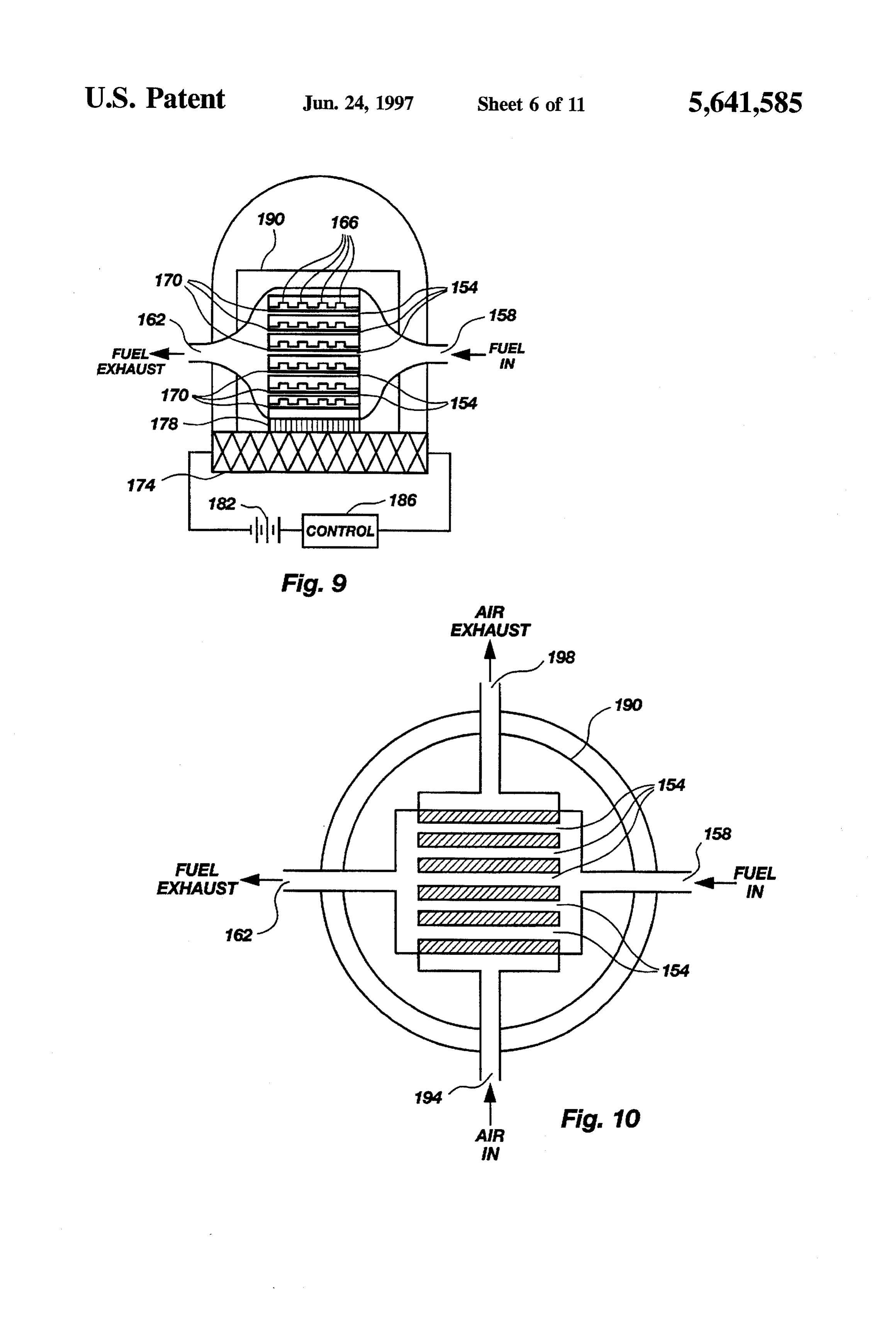
which the inventive power supply system is incorporated FIG.9 depicts across sectional view of an embodiment of thereby preventing damage to other components of the the fuel cell system which incorporates planar fuel cells portable device. The superinsulator and heat management FIG. 10 depicts atop view of the fuel cell system of FIG. system also serve to prevent heat or heated exhaust from 9 which utilizes planar fuel cells coming in contact with the user and causing injury.
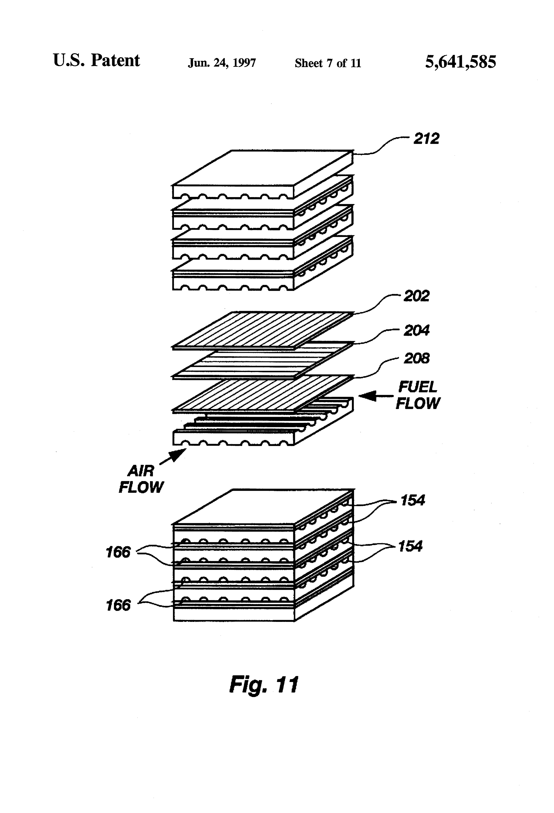
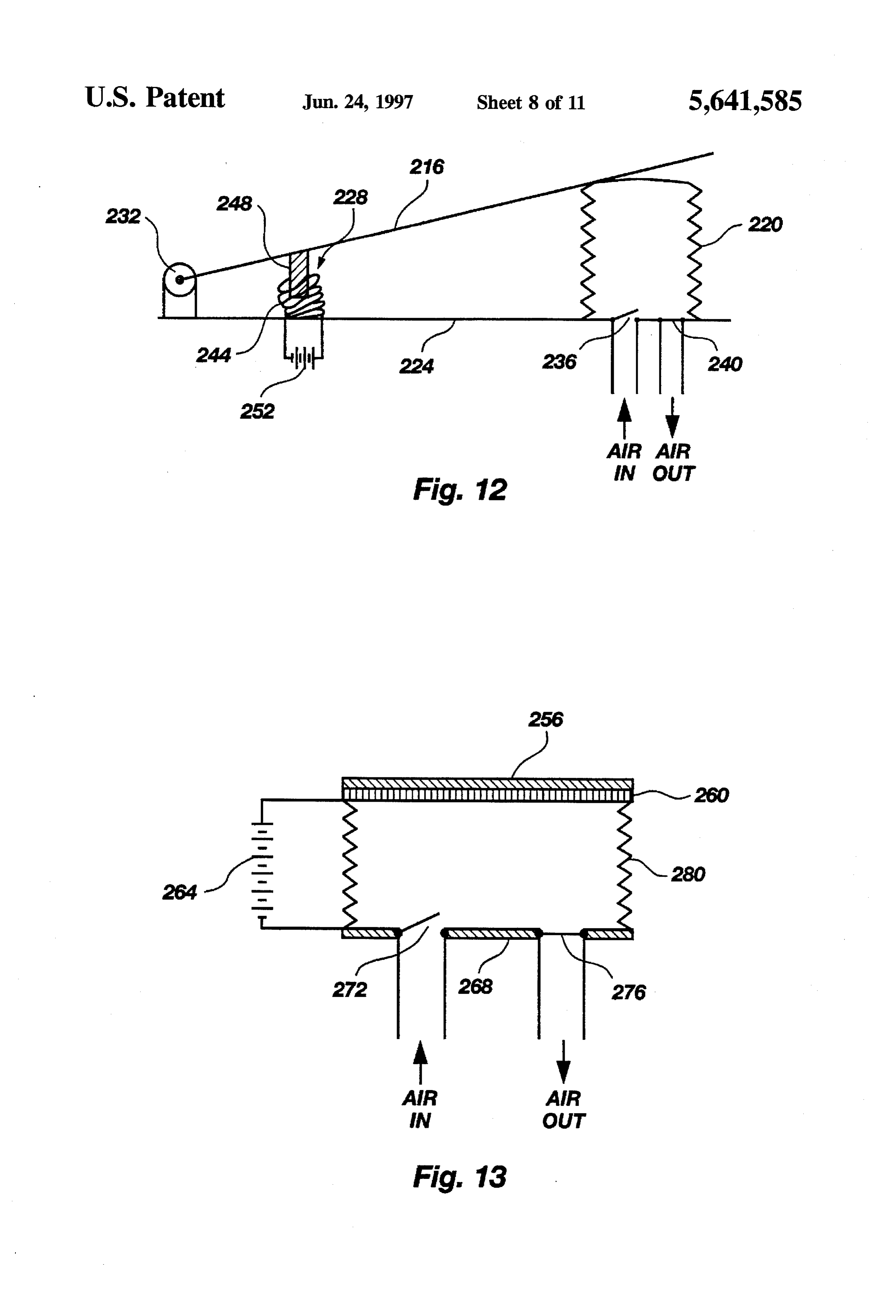
Accordingly, it is a primary object of the presentinvention oneFIG. fuel 11 is a perspective view of the planar fuel cells with cell being shown in exploded form.
to provide a source of direct current electricity which is not FIG. 12 is a cross sectional view of a bellows air pump subject to discharge and is designed for use in devices requiring small portable sources of direct current electricity utilizing a magnetic actuator.
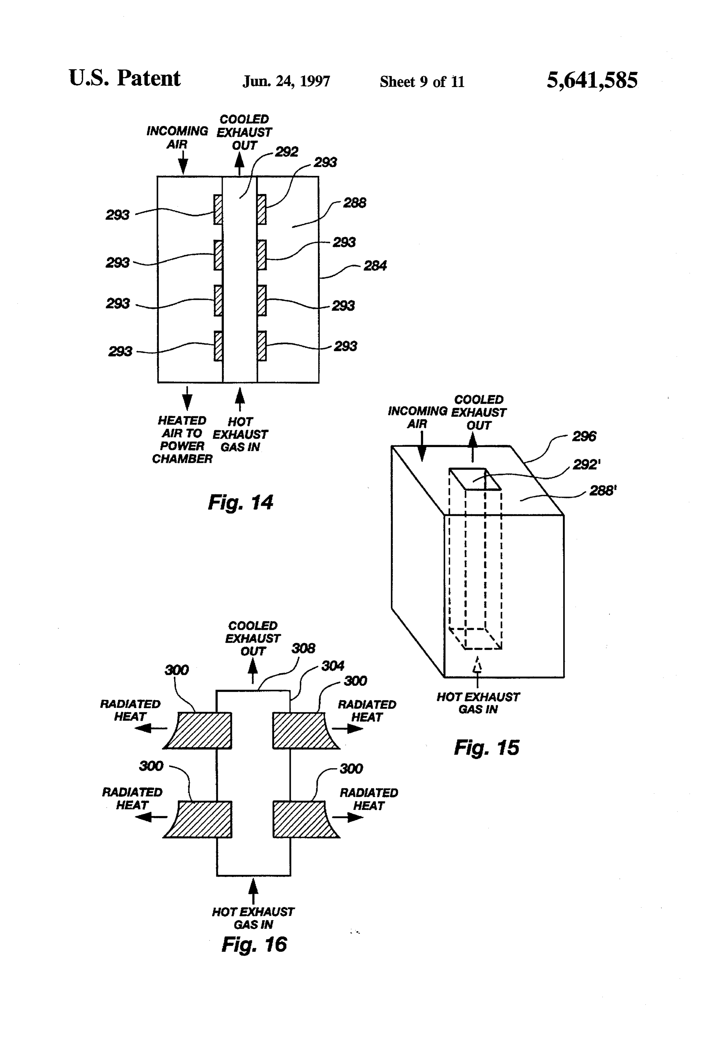
such as cellular phones, notebook computers, medical 10 FIG. 13 is a cross sectional view of a bellows air pump equipment, and the like. employing an electrostatic actuator. It is a further object of the present invention to provide a FIG. 14 is a cross sectional view of a cylindrical heat source of direct current electricity which will begin provid recuperator.
ing power within a relatively small amount of time after FIG. 15 is a perspective view of a rectangular heat operation is initiated. 15 recuperator.
A still further object of the present invention is to provide FIG. 16 is a cross sectional view of heat recuperator a source of direct current electricity which utilizes a system which utilizes highly thermally conductive vanes to replenishable, commonly available, fuel supply. channel heat from the exhaust gases to other areas of the An additional object of the present invention is to provide 20 system.
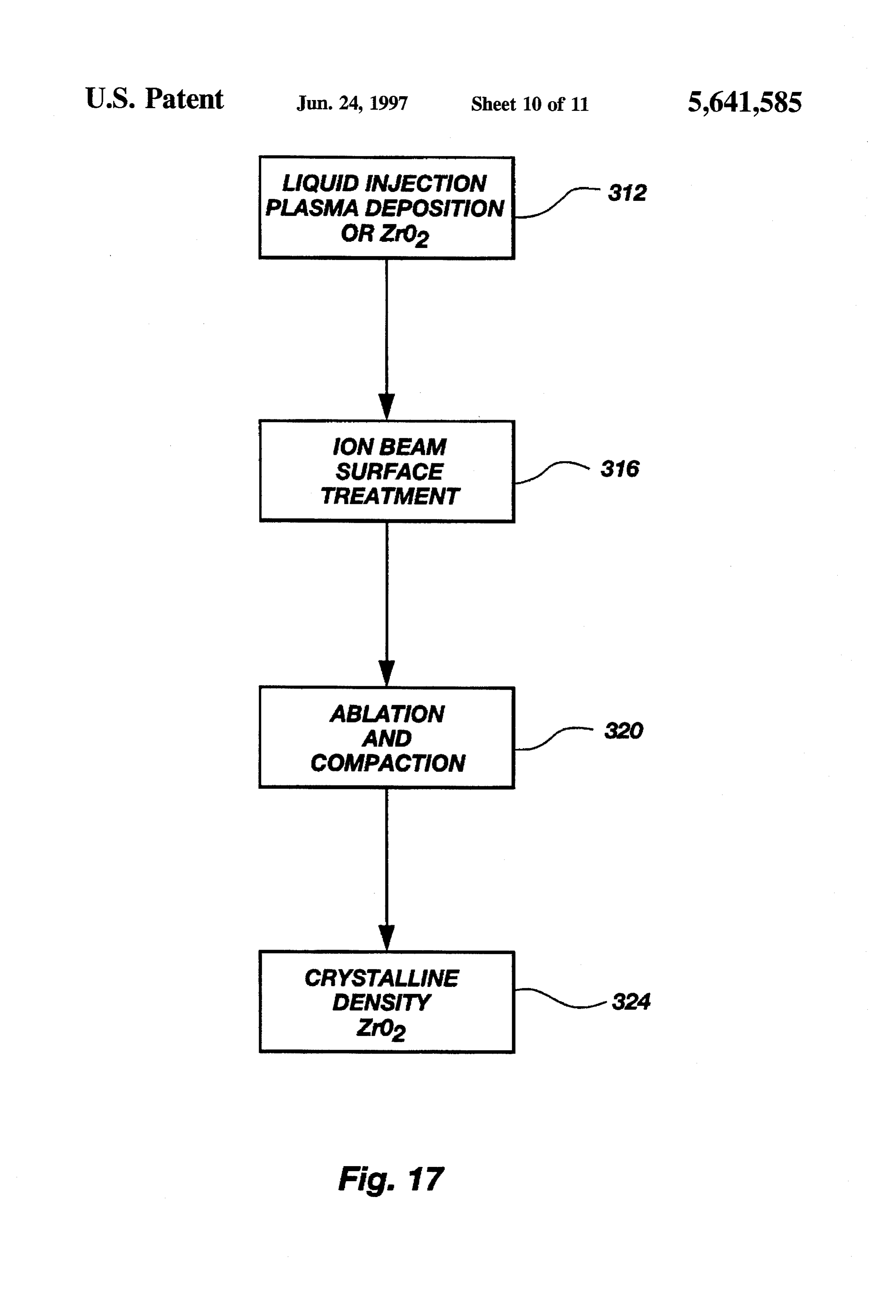
a system which incorporates heat management such that the FIG. 17 is a block diagram of the method of applying high operating temperatures of the ceramic fuel cell do not ZrO using a pulsed ion beam to achieve the desired density. result in damage to the portable device or injury to the user. FIG. 18A through 18C depict the steps used in applying These and other objects of the present invention will ZrO2 become more fully apparent from the following description 25 FIG.to 18A a substrate with a pulsed laser beam. represents the application of the pulsed laser and appended claims or may be learned by the practice of the beam.
invention as set forth herein.
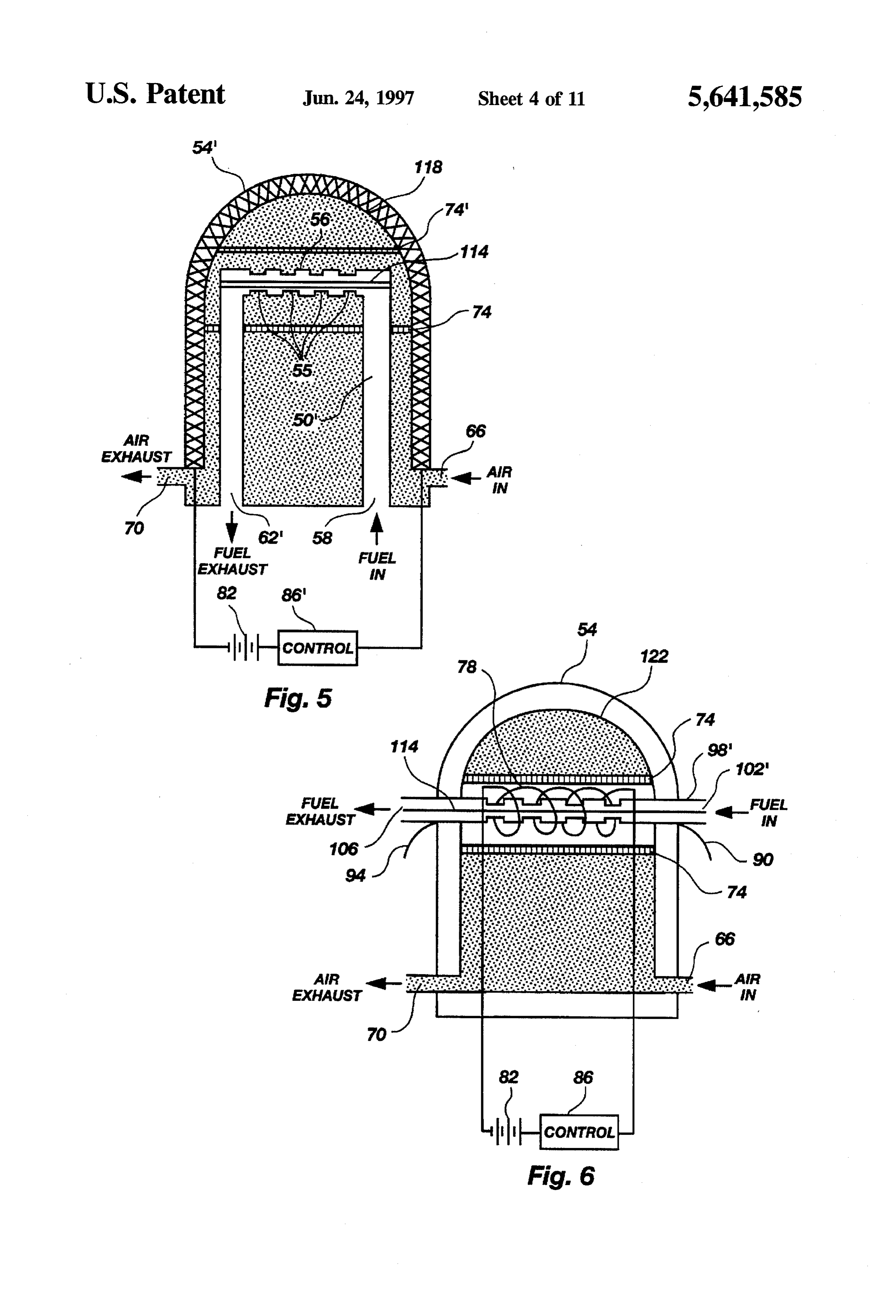
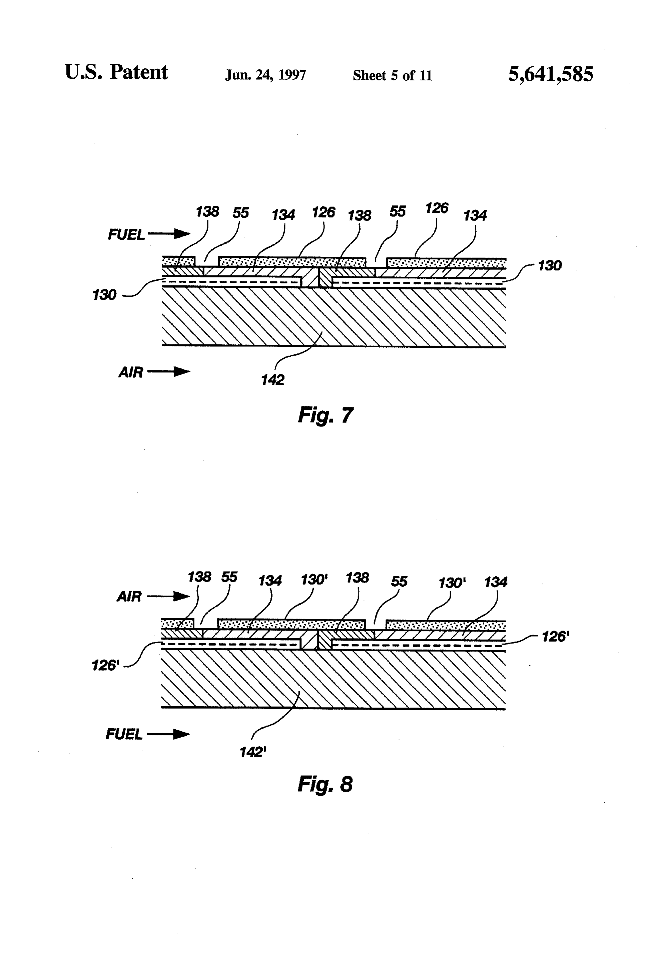
BRIEF DESCRIPTION OF THE DRAWINGS
FIG. 18B depicts the vapor blow off which occurs.
FIG. 18C illustrates the devise layer of ZrO2 achieved.
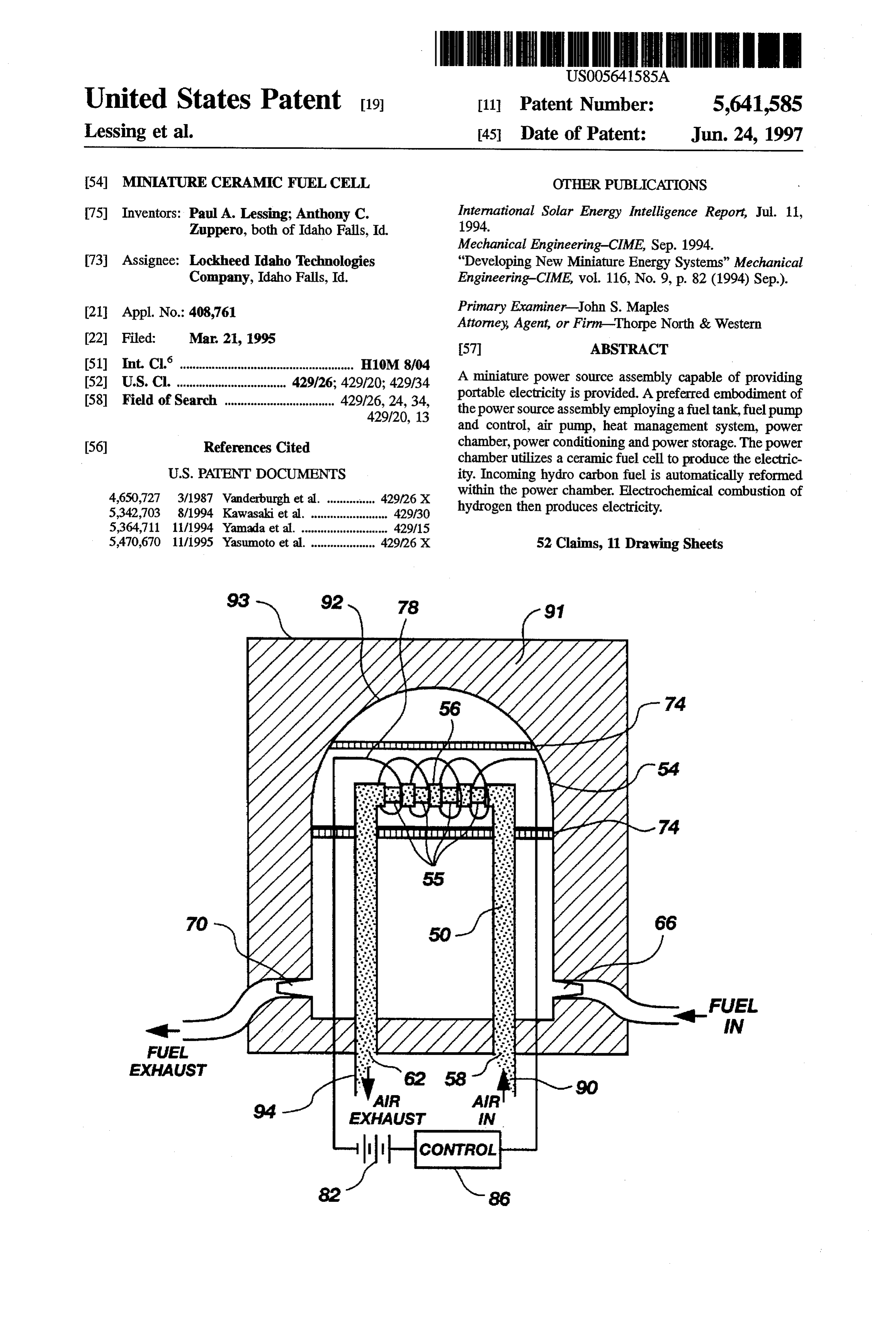
In order to more fully understand the manner in which the 30 above-recited and other advantages and objects of the DETALED DESCRIPTION OF THE presentinvention are obtained, a more particular description INVENTION of the invention briefly described above will be rendered by Reference is now made to the embodiments and methods reference to the presently understood best mode for making illustrated in FIGS. 1 through 18 wherein like numerals are and using the same, as illustrated in the appended drawings. used to designate like parts throughout. In FIG. 1 illustrates Understanding the these drawings depict only typical 35 the power supply system of the present invention, desig embodiments of the invention and are, therefore, not to be nated generally as 10, as it might appear in use with a considered as limiting of its scope, the invention will be cellular phone 14. The housing surrounding power supply described with additional specificity and detail through the system 10 is depicted as being open so as to reveal the use of the accompanying drawings in which: components therein, although in actual use the housing of FIG. 1 depicts the presently preferred embodiment of the cellular phone 14 would completely enclose the components inventive power supply system as it might appear when of power supply.
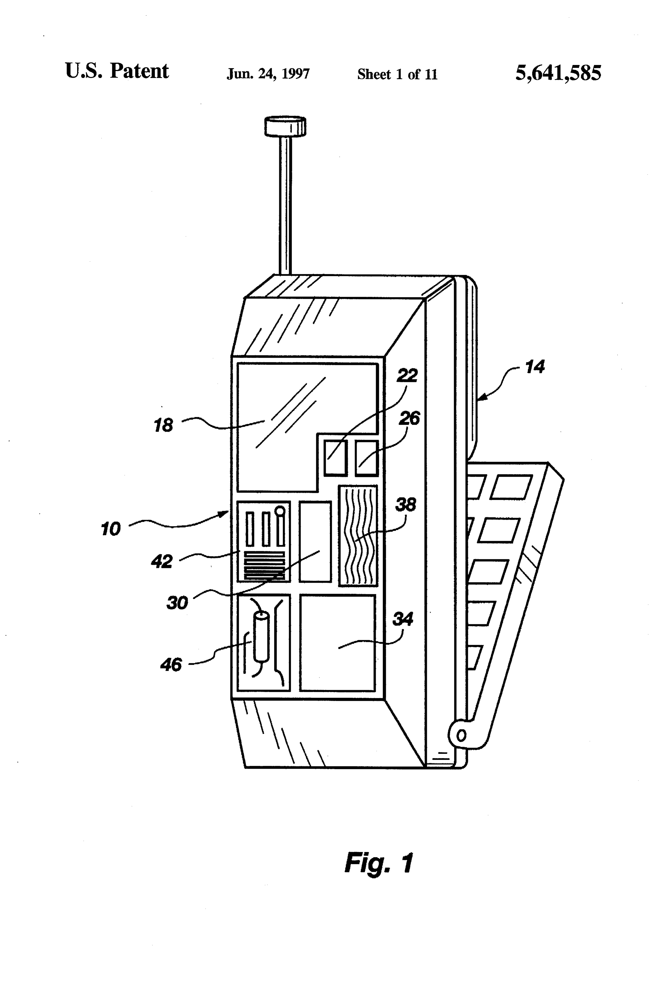
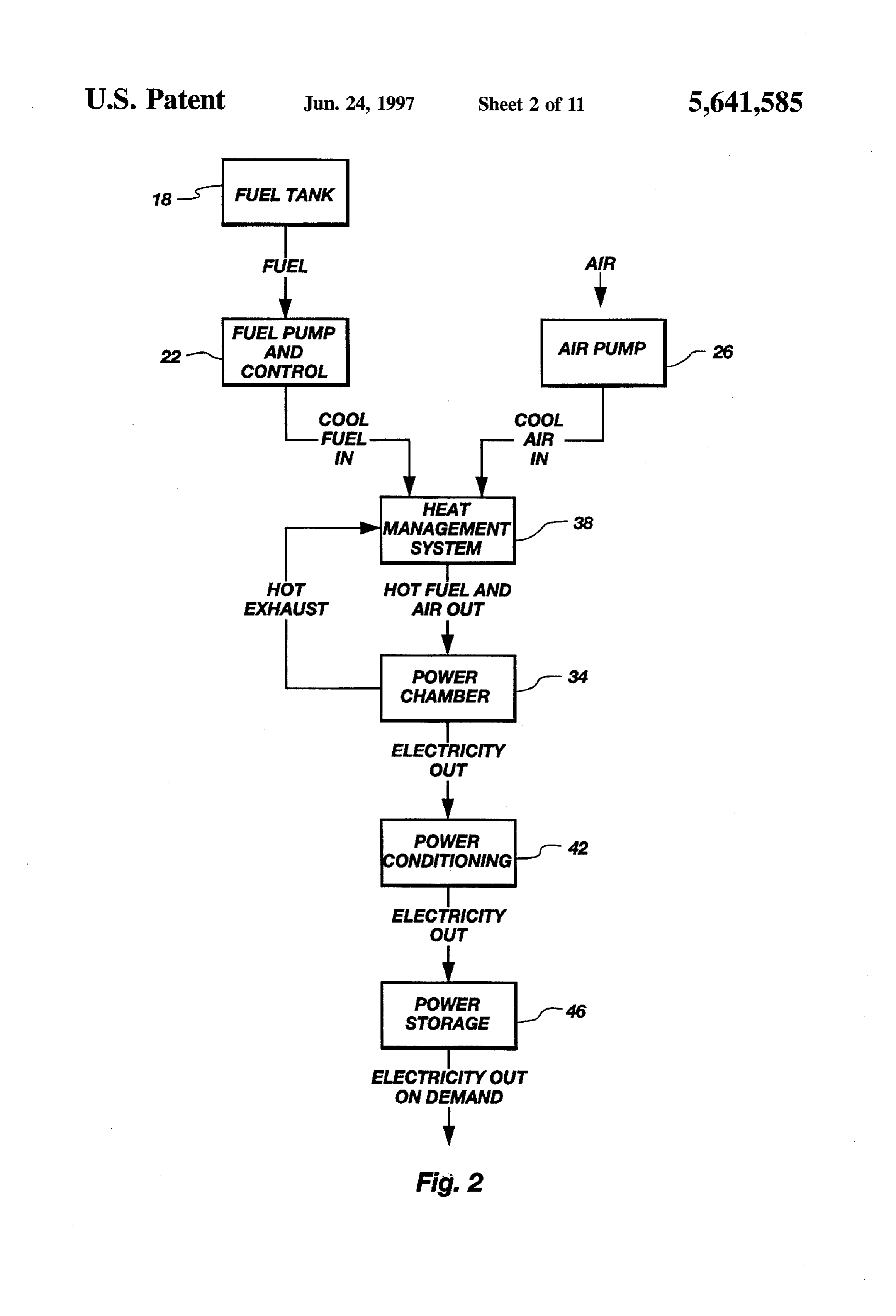
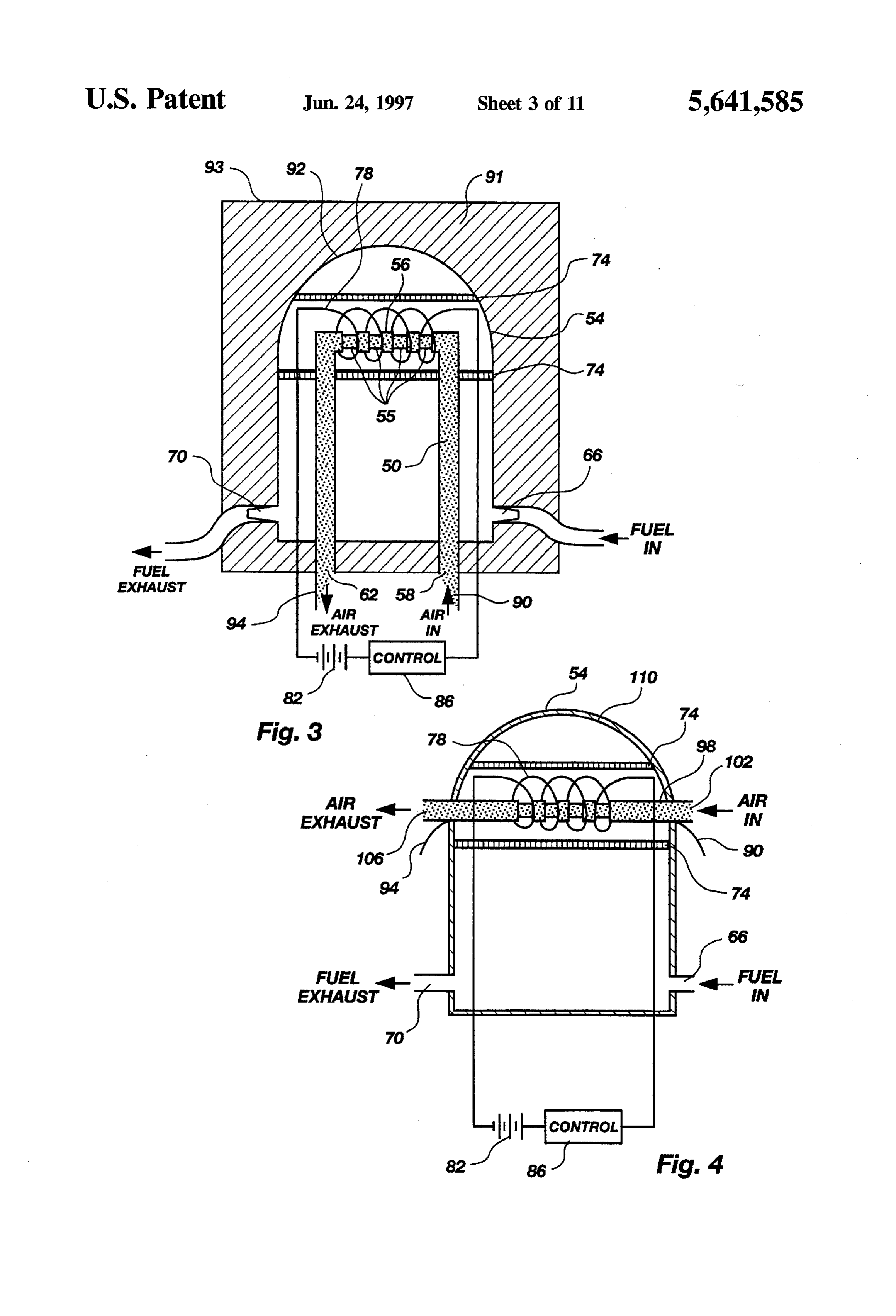
incorporated in a cellular phone. As illustrated, a presently preferred embodiment of the FIG. 2 depicts a preferred embodiment of the present power supply system of the present invention incorporates a invention in block diagram form. fuel tank 18, a fuel pump 22, an air pump 26, a start up FIG. 3 depicts a presently preferred embodiment of the 45 device 30, a power chamber 34, a heat management system inventive miniature cross sectional view of a fuel cell 38, a power conditioner 42, and power storage 46. Various wherein air is circulated through a u-shaped conduit housed embodiments of power chamber 34 are further illustrated in within a fuel filled container. FIGS. 3 through 6 and 9.
FIG. 4 depicts a cross sectional view of another presently 50 As will be appreciated these components could be preferred embodiment of the inventive miniature fuel cell arranged in differing ways to adapt to the existing configu wherein air is circulated through a straight conduit housed ration of the power pack of a variety of devices such as with a fuel filled container. notebook computers, medical devices, and other devices FIG. 5 depicts yet another cross sectional view of an requiring portable sources of power. Thus, the arrangement embodiment of the inventive miniature fuel cell wherein fuel 55 of the components is not critical to the operation of the is circulated through a u-shaped conduit housed within a present inventive power supply system.
container filled with air. In use fuel, from fuel tank 18, and air would be pumped, FIG. 6 depicts another cross sectional view of an embodi by fuel pump 22 and air pump 26 respectively, into power ment of the inventive fuel cell wherein fuel is circulated chamber 34. Typically hydrocarbon fuels would be utilized. through a straight conduit housed within a container filled Startup device 30 would allow the power producing process with air, taking place within power chamber 34 to begin. FIG.7 depicts a cross sectional view of the detail of the Specifically, fuel entering power chamber 34 would be tubular fuel cells disposed on the u-shaped conduit of FIG. reformed to produce hydrogen. Within power chamber 34 3 and the straight conduit of FIG. 4. would be the electrochemical combustion of the hydrogen FIG. 8 depicts a cross sectional view of the detail of the 65 allows for the production of direct current electricity. The tubular fuel cells disposed on the u-shaped conduit of FIG. direct current electricity would then be conditioned, if 5 and the straight conduit of FIG. 6. required, by power conditioner 42. The electricity would
Page 15
then be routed to power storage device 46 where it would be a supply of hydrogen which is then electrochemically com available for use. busted to produce the desired electricity. Porous tube 74 also FIG. 2 better illustrates this process in a flow chart or acts as a radiation shield. In addition, porous tube 74 functional block diagram form. As shown, fuelis supplied to includes a reflection coating 75 which reflects heat back in fuel pump 22 from fuel tank 18. Fuel pump 22 delivers cool on the reaction.
fuel to heat management system 38. Simultaneously, air is Resistance heating element 78 provides heat to begin and, delivered by air pump 26 to heat management system 38. if necessary sustain, the electrochemical reaction. Reflective The air and fuel are heated in heat management system 38 coating of porous tube 74 reflects the energy of resistance prior to being delivered to power chamber 34. The exhaust heating element 78thus maximizing the input power. Resis from power chamber 34 is routed back to heat management 10 tance heating element 78 is supplied with power via power system 38 so as to aid the system in maintaining the heat source 82. Resistance heating element control 86 acts to turn necessary for operation and to allow exhaust gases to be resistance heating element 78 on and off as required and also adequately cooled before being allowed to vent to surround acts to insure that power source 82 remains charged. ing areas. Proper heat management and adequate cooling of Preferably, resistance heating element 78 will be constructed exhaust gases is required to allow operation of the system 15 of Nichrome (NiCr) or Tungsten (W). without damage to the portable device in which it is incor As will be appreciated, the electrochemical combustion of porated or injury to users of the device. hydrogen occurs at a high temperature. Without outside Electricity from power chamber 34 is routed to power input, the level of reaction required to produce electricity in conditioning 42 so that the power being produced can be 20 usable quantity can take hours to reach. With the addition of conditioned, if necessary, so as to be usable by the portable resistance heating element 78, this turn on time can be device it is incorporated into. The power is then routed to substantially reduced or effectively eliminated. power storage 46. Power storage 46 stores powerfor use on As will be further appreciated, the cellular phone, note demand. book computer, or other portable device into which the In FIG. 3, a currently preferred embodiment of power present invention is incorporated must be protected from the chamber 34 of the present invention is illustrated. In opera 25 high temperatures, on the order of 1000 C, involved. In tion power chamber 34 provides for the reformation of an addition, the users of the devices must be protected from input fuel to provide hydrogen. The electrochemical com injury which could result from coming in contact with such bustion of this hydrogen supplies the electrolyte needed thus high temperatures. Super insulator 91 is designed to allow producing direct current electricity to power cellular phones, 30 the internal surface 92 temperature to be extremely high computers, medical equipment or other device requiring a while maintaining the outside surface 93 temperature to be small portable power source. touchable without injury. To achieve this, super insulator 91 As indicated, airflows in and out of u-shaped conduit 50 is constructed of a fibrous ceramic material such as space which is housed in container 54. Container 54 is preferably shuttle tile.
constructed of a metallic material and is on the order of 1 cm 35 Negative power lead 90 and positive power lead 94 allow high by 1 cm wide. Container 54 is thus much smaller than for power to be drawn off from the system and routed to devices previously employed. power conditioning, if necessary and then on to power The preferred diameter of u-shaped conduit 50 is 1 to 2 storage. Electricity is then available on demand to the millimeters. U-shaped conduit provides a single duct which cellular phone, notebook computer, or other portable device. allows for simplicity of manifolding. Only one connection Power available at negative power lead 90 and positive need be made to u-shaped conduit input port 58 and likewise power lead 94 can also be routed to power source 82 by to u-shaped conduit output port 62. control 86 as necessary.
Notches 55 represent power cells which are discussed in FIG. 4 illustrates another embodiment of the present detail in relation to FIGS. 7 and 8. The power cells are invention. This embodimentis similar to the embodiment of placed along cross member 56 of u-shaped conduit 50. The 45 FIG. 3 in that airflows in the conduit and fuel flows in the number of power cells is dependent on the desired voltage. container. In this embodiment, a straight tube 98 is Air flows into u-shaped conduit 50 at u-shaped conduit employed. Air enters straight tube 98 at straight tube input input port 58 and exhaust airflows out of u-shaped conduit port 102 and air exhausts out straight tube output port 106. 50 at u shaped conduit output port 62. Simultaneously, fuel Also depicted in this embodiment is an interior reflective flows into container 54 at container input port 66 and fuel 50 coating 110. Interior reflective coating 110 is applied to the exhaust flows out at container output port 70. The preferred interior surface of container 54 and is designed to act as a fuel will be a hydrocarbon fuel such as butane, propane, or heat shield.
similar hydrocarbon fuels. Turning to FIGS.5 and 6 embodiments whereinfuel flows The utilization of container 54 allows for a number of through u-shaped conduit 50' and straight conduit 98' are advantages. For example, once operation of power chamber 55 illustrated. In these embodiments airflows through container 34 is begun, apartial vacuum may be drawn on container 54. S4.
This can assist in sustaining the heat and other conditions Specifically, FIG. 5 illustrates an embodiment in which necessary for continued operation of power chamber 34 with fuel flows into u-shaped conduit 50' through u-shaped con little or no external inputs. Container 54 can act in many duit input port 58. Fuel exhaust flows out of u-shaped respects as a thermos bottle, containing the heat of the conduit 50' at u-shaped conduit output port 62. electrochemical reaction. It should be noted, however, that Simultaneously, air enters container 54 through container the system will eventually deplete its supply of oxygen if input port 66 and air exhaust exist the system through remaining in the partial vacuum state. Fuel flowing through container output port 70.
container 54 is automatically reformed within container 54 U-shaped conduit 50' contains catalyst element 114. Cata due to the presence of porous tube 74. Porous tube 74 65 lyst element 114 is constructed of Nickel, Aluminum, and contains Nickel, Aluminum, and ceramic. This combination ceramic materialso as to provide for reformation of incom acts to reform the incoming hydrocarbon fuel thus providing ing fuel within u-shaped conduit 50" Reformation of the
Page 16
hydrocarbon fuel is required to provide the hydrogen nec the anode and cathode respectively. Oxygen from the air is essary for the electrochemical reaction which produces the consumed by the cathode and is conveyed via the electrolyte desired electricity. (in the form of negatively charged oxygen ions) to the anode. In this embodiment porous tube 74 need not be made of There, the oxygen combines with hydrogen to produce water Nickel, Aluminum, and ceramic but may employ any sub and with carbon monoxide to produce carbon dioxide. This stance which will provide adequate radiation shielding. flow of oxygen ions results in an accumulation of both Typically porous tube 74 will be constructed of a thin negative charge at the anode and positive charge at the ceramic material. cathode. This flow of charge constitutes DC current and can This embodiment also employs a starter system other than be used to power devices such as cellular phones, notebook a NiCr or W wire resistance heating element. Here an 10 computers, computers, and other portable devices. Oxygen electrical burner 118, similar to burners used in electric ions will flow only when the difference in electric potential ranges, is employed. Heat is radiated from electrical burner between anode and the cathode is less than a certain voltage 118 as needed to start and sustain the electrochemical (about 0.7 to 1.0 Volt); this serves to regulate the voltage of reaction. Power source 82 supplies power to electrical each cell.
burner 118 when in use. Controls 86' turn electrical burner 15 The number of cells utilized in a given application is 118 on and off as needed and insure that power source 82 is dependent on the voltage desired. Each cell produces in the recharged when required. range of 0.7 volts to 1 volt. Cells are added by linking, via Finally, container 54' is preferably constructed of an interconnect 138, until the voltage required for the cellular oxidation resistant material. Oxidation resistant metal alloys 20 phone, notebook computer, or other portable device is or ceramics are acceptable materials for the manufacture of attained.
container 54. Turning to FIG. 9 an alternate embodiment of the current Turning to FIG. 6, an embodiment using straight conduit system is depicted. In this embodiment cells having a planar 98 is employed. Fuel flows through straight conduit 98' and geometry are employed. Plates having a plurality of pas is reformed due to the presence of catalyst element 114. The 25 sageways therethrough are employed. The plates are con resulting hydrogen supplies the electrochemical reaction structed so that the passageways for fuel and passageways which produces the desired electricity. for air are perpendicular to each other on opposite sides of Also depicted in this embodiment is a double walled the plates.
configuration of container 54. Interior wall 122 serves to The passageways allow for the passage of air and fuel provide additional heat shielding and to aid in maintaining 30 necessary for the electrochemical reaction to occur. In the the temperatures necessary for the electrochemical combus embodiment illustrated in FIG. 9, fuel enters the fuel pas tion of hydrogen. sageways 154through input port 158 while exhaust exits the FIG. 7 shows the details of the cells placed along system through output port 162. Simultaneously, air flows u-shaped conduit 50 of FIG. 3 and straight conduit 98 of through air passageways 166. Cells are joined together via FIG. 4. In the embodiments of FIGS. 3 and 4, airflows along 35 planar interconnects 170.
the inside of the conduits while fuel flows along the outside. The planar cells are connected to a plane burner 174 via As illustrated in FIG. 7, the cells placed along the conduits a physical connection 178. Cement, braze, ceramic or other utilize anode 126, cathode 130, electrolyte 134, and inter material or method may be employed to physically connect connect 138 placed along a porous support member 142. the planar cells to plane burner 174. Plane burner 174 Anode 126 is preferably manufactured of a substance 40 provides the initial energy necessary to start up the system. containing Nickel, Aluminum, and ceramic. Cathode 130 is Power to plane burner 174 is provided by burner power preferably manufactured of LaSrMnO as is porous support supply 182. Burner control 186 turns plane burner 174 on member 142. Electrolyte 134 may be ZrO, CO, or similar and off as required to start or maintain the electrochemical material. Interconnect 138 is constructed of LaSrCrO or reaction. Burner controls 186 also insure that burner power similar material. 45 supply 182 stays charged by drawing current off of negative Turning to FIG. 8, the details of the cells placed along power lead 90 and positive power lead 94 as required. Cap u-shaped conduit 50' of FIG. 5 and straight conduit 98 of 190 provides radiation shielding and may employ a reflec FIG. 6 are illustrated. In the embodiments of FIGS. 5 and 6, tive coating on the internal surface which serves to maxi fuel flows along the inside of the conduits while air flows mize the energy reflected back into the system and used to along the outside. As illustrated 22 in FIG. 8, the cells placed 50 maintain the heat for the electrochemical reaction. along the conduits utilize a different configuration of anode FIG. 10 better illustrates the flow of fuel and air through and cathode to accommodate the difference in the air and fuel passageways 154 and air passageways 166. As earlier fuel flow. As shown anode 126 and cathode 130' and placed discussed, fuel enters the system via fuel input port 158 and differently although electrolyte 134 and interconnect 138 spent fuel is exhausted through fuel output port 162. As remain the same. Anode 126 and cathode 130 are, however, 55 illustrated here, air enters the system through air input port made of the same materials as used in the embodiment of 194 and air exhaust exits via air output port 198. FIG. 7. FIG. 11 depicts a number of cells stacked together and Each element is placed along a porous support member shows an exploded view of a single cell. As illustrated, a 142 which maintains the same placement as support mem planar cell utilizes a planar anode 202, a planar electrolyte ber 142 of FIG. 7 but here support member 142 is con 204, a planar cathode 208, and a planar interconnect 212. structed of different materials. Specifically, support member CoNibrazing is typically employed to achieve the desired 142 is made of a composition of Nickel, Aluminum, and joining of the cells. Planar anode 202 is typically manufac ceramic. This combination allows for the automatic refor tured of 250 pum Nickel Oxide or Zirconium Oxide. Planar mation of the hydrocarbon fuel into the hydrogen necessary electrolyte 204 is typically manufactured of 3 m Zirconia for the electrochemical reaction. 65 (ZrO2). Planar cathode 208 is typically manufactured of 250 When a cellis operating, a continuous stream of reformed im Lanthanum Manganese Oxide. Finally planar intercon fuel (hydrogen and carbon monoxide) and air are supplied to nector 212 is typically manufactured of 2500 um Nickel
Page 17
Aluminum. The Nickel Aluminum of the interconnector Another aspect of the present system which requires provides the catalyst required for automatic reformation of management is the production of high heat. Although the hydrocarbon fuels. fibrous insulation serves to protect surrounding components As will be appreciated, the geometry of this type of fuel from damage and the user from injury due to direct contact, cells is not critical. Geometries other than the tubular geometry and planar geometry depicted in the foregoing there is still the issue of gases which are exhausted from the system at high temperatures. Since the chemical reaction embodiments are thus considered to be within the scope of taking place requires maintenance heat it would be highly the present invention. advantageous to use the exhaust gases to the advantage of As discussed above, a substantial amount of air must be the system by recycling the heat back into the system. moved through the power chamber to supply the oxygen for 10 FIG. 14 illustrates one method of heat recuperation which the process. Air flow should be on the order of 10 cc/sec to utilizes a cylindrical chimney 284 having an outer duct 288 achieve adequate power output. Simple convective flow is and an inner duct 292. Athermally conductive material such not sufficient to allow the system adequate oxygen.
Several practical problems arise in moving such quantities as metal or ceramic is employed in inner duct 292 such that of air. For example, when the present inventive system is 15 iscoolheated air entering outer duct 288 of cylindrical chimney 284 incorporated into a cellular phone, any device utilized to cylindricalbychimney hot exhaust gas entering inner duct 292 of
move the air must be quiet and efficient. Devices which create substantially noticeable noise will interfere with the This system forms a counter flow heat exchanger. As user's ability to carry on a conversation. Thus, it is highly illustrated, exhaust gases from the power chamber would desirable oZ reduce the amount of noise associated with air
flow up inner duct 292 while incoming air flowed down movement as much as possible. outer duct 288. As shown, exhaust gases leaving inner duct Although a fan could be utilized in some applications, a 292 of cylindrical chimney 284 have been cooled to a point better approach is to use a bellows device. Bellows are quiet where they can be safely vented.
and efficient and well suited to this application. FIGS. 12 and FIG. 15 illustrates an alternative heatrecuperation system 13 depict various embodiments of belows which can be 25 which is similar to that depicted in FIG. 14. Here a rectan utilized. As will be appreciated numerous other bellows gular chimney 296 is constructed of flatplates. A number of configurations can be employed to achieve the same effect. materials, such as ceramics or metals, could again be In FIG. 12, a bellows utilizing a hinged plate 216, bellows employed as the heat exchanger material. 220, base plate 224, and actuator 228. Hinged plate 216 is An outer duct 288’ and an inner duct 292 are again preferably constructed of a flexible lightweight plastic mate 30 employed with the inner duct 292 incorporating the heat rial or other lightweight material. Hinged plate 216 requires exchanger material. Hot exhaust gases flow up inner duct little strength and can therefore be made of a variety of 292 while cool airflows down outer duct 288 thus being materials. Bellows 220 will preferably be made of a very heated in the process.
thin mylar plastic. FIG. 16 depicts another type of heat management system The hinged plate pivots, to a limited degree, around hinge 35 wherein a number of vanes 300 are inserted into chimney 232 as bellows 220 expands and contracts. Bellows 220 304. Chimney 304 is depicted as rectangular although a expands and contracts as air enters through input valve 236 variety of geometric configuration could be employed. and exits through output valve 240. Airflow is indicated on Exhaust gases travel up shaft308 of chimney 304. Vanes 300 the drawing with the air exiting bellows 220 through output act to conduct heat away into another region. Vanes 300 are valve 240 being returned to the power chamber. composes of a highly thermally conductive material such as Actuator 228 employs a solenoid coil 244 and solenoid diamond film. Although diamond film can be expensive, the rod 256 which are powered by solenoid power source 252 as extremely Small size of the inventive system allows for required. Actuator 228 is magnetic. practical use of such materials. As will be appreciated, other FIG. 13 depicts an electrostatically actuated bellows con highly thermally conductive materials could also be figuration. A wide flat mylar sheet 256 having aluminized 45 employed.
electrically conducting film 260 is connected to a high This technique, employing vanes 300, can be employed to voltage power source 264. A base sheet 268 having a sheet conduct heat to an area where incoming air is contained so input valve 272 and a sheet output valve 276 is also as to heat it. Similarly, vanes 300 can be employed to connected to high voltage power source 264. conduct heat to an area where fuel is contained so as to heat Base sheet 268 and mylar sheet 256 can then be made to 50 it prior to its entry to the power chamber. attain a charged status. If base sheet 268 and mylar sheet 256 The ZrO2 electrolyte layer is critical to the feasibility of have like charge, either positive or negative, base sheet 268 producing the miniature fuel cell of the present invention. and mylar sheet 256 will repel each other and force planar Additionally, the speed of application is an important con bellows 280 to expand thus drawing in air through sheet sideration in terms of manufacturing, particularly mass input valve 272. If base sheet 268 and mylar sheet 256 55 manufacturing. A process which is long increases costs and become oppositely charged base sheet 268 and mylar sheet may make an otherwise viable product non-competitive. 256 then attract each other. This attraction forces bellows One of the keys to producing a miniature fuel cell is the 280 to contract as the sheets are drawn together and expelair production of the key electrolyte layer, as depicted in FIGS. through sheet output valve 276. Air leaving bellows 280 7, 8 and 11. Forbest performance, the electrolyte layer must through sheet output valve 276 is returned to the power have crystalline density and chemical properties and be a gas chamber. As will be appreciated, bellows in otherforms and tight barrier. In addition, to be commercially successful, the using other activation means could be employed to achieve electrolyte layer needs to be capable of manufacture at the same result. For example, a bellows system utilizing a industrially significant rates with industrially acceptable working liquid which turns into a gas at the operating yields per batch.
temperatures of the system thereby actuary the bellows as Methods of applying ZrO typically are slow, but achiev the gas rises. Further, a piezo actuated planar pump could ing the desired density, or fast, but creating a loosely packed also be utilized to achieve the movement of air required. or snow like layer of ZrO2. To be commercially viable, a
Page 18
method of applying the ZrO which can be accomplished catalyst means for reforming the fuel into the chemical quickly while attaining the desired density must be components needed for oxidation; and employed. electric starter means for adding heat to the system Apreferred method of manufacturing the electrolyte layer thereby to initiate oxidation. is depicted in block diagram form in FIG. 17. The ZrO is ity2.asAdefined power source assembly for use in providing electric in claim 1 wherein the fuel cells are cylindrical first applied to a substrate using a liquid plasma deposition process as shown at step 312. This process rapidly lays down having an inner surface and an outer Surface. a layer of ZrO2 and results in a density of ZrO2 which is ity3.asAdefined power source assembly for use in providing electric in claim 2 wherein the anode resides on the approximately half of the desired crystalline density.
10 outer surface of the cylindrical fuel cell and the cathode
At step 316 on the ZrO applied to the substrate in step resides on the inner surface of the cylindrical fuel cell. 312 is treated with an ion beam. This process is accom 4. A power source assembly for use in providing electric plished by utilizing electricity to create a stream of very ity as defined in claim 2 wherein the anode resides on the energetic ions which carry the energy to the surface layer of inner surface of the cylindrical fuel cell and the cathode the target, here the ZrO applied to the substrate in step 312. 15 resides on the outer surface of the cylindrical fuel cell. Apulsed ion beam, is used to deposit energy uniformly into 5. A power source assembly for use in providing electric just the top 2 to 20 micrometers of the ZrO2. The ion beam ity as defined in claim 1 wherein the fuel cells are planar. is typically operated for less than 200 nano-second long 6. Apower source assembly as defined in claim 1 wherein pulses utilizing relatively small energies. This process melts the air pump means comprises a bellows pump. or vaporizes the 2 to 20 micrometer layer. Additional treat 20 7. A power source assembly as defined in claim 1 wherein ment results in the compaction and ablation of step 320. the air pump means comprises a bellows pump having a This process has been used to treat 100 to 200 square magnetic actuator.
centimeters of material per minute when operation in the the air pump source 8. Apower means assembly as defined in claim 1 wherein comprises an electrostatically actuated 100 Kilowatt and above power level. This treatment pro planar air pump.
duces a thin, dense polycrystalline layer of material that is 25 9. A power source assembly as defined in claim3 wherein Substantially crystalline density and provides a substantially the catalyst means comprises a Nickel Aluminum Ceramic sealed barrier as desired and represented by step 324. tube substantially surrounding the cylindrical fuel cells FIGS. 18A, 18B, and 18C depict another method of thereby automatically reforming the incoming fuel into the treating ZrO to produce a dense layer. This method utilizes chemical components required for the electrochemical reac a pulsed laser beam which is applied to loosely packed ZrO. 30 tion which produces electricity.
As shown in FIG. 18A a pulsed laser beam 328 is directed 10. A power source assembly as defined in claim 4 to the non-dense ZrO 332 residing on substrate 336. The wherein the catalyst means comprises a Nickel Aluminum pulsed laser used to produce pulsed laser beams 328 is Ceramic Element disposed at the inner surface of the cylin typically in the range of 10 MW/cm and 1000 MW/cm drical fuel cells.
The surface annealing caused by this process results in the 35 11. A power source assembly as defined in claim 1 dense ZrO layer 344 depicted in FIG. 18C. wherein the starter means comprises a resistance heating The achievement of a density of ZrO, allows for the better element, conduction of ions and allows for the electric power output 12. A power source assembly as defined in claim 11 or power density. Power density is required to make the wherein the resistance heating element comprises a miniature solid oxide fuel cell of the present invention a Nichrome wire.
viable option for replacement of batteries in cellular phones, 13. A power source assembly as defined in claim 11 notebook computers, and other portable devices. wherein the resistance heating element comprises a Tung In FIG. 18B vapor blow off 340 resulting from the sten wire.
application of the pulse laser beam is depicted. 14. A power source assembly as defined in claim 1 The invention may be embodied in other specific forms 45 wherein the starter means comprises a burner. without departing from its spirit or essential characteristics. 15. A power source assembly as defined in claim 1 The described embodiments are to be considered in all wherein the first routing means comprises a container and respects only as illustrative and not restrictive. The scope of the second routing means comprises a conduit. the inventionis, therefore, indicated by the appended claims, 50 16. A power source assembly as defined in claim 15 rather than by the foregoing description. All changes which wherein the container further comprises a reflective coating come within the meaning and range of equivalency of the disposed interior to the container thereby reflecting energy claims are to be embraced within their scope. back into the electrochemical reaction. We claim: 17. A power source assembly as defined in claim 15 1. A self-contained power source assembly for use in 55 wherein the container comprises a double walled container providing electricity, the power source assembly compris thereby containing energy within the container and sustain ing: ing the electrochemical reaction. a plurality of fuel cells connected in series, each fuel cell 18. A power source assembly as defined in claim 15 having an anode, a cathode, and electrolyte for produc wherein the conduit comprises a straight conduit. ing electricity by oxidation of supplied fuel; 19. A power source assembly as defined in claim 15 fuel source means for supplying fuel to the fuel cells; wherein the conduit comprises a u-shaped conduit. 20. A power source assembly as defined in claim 1 first routing means for directing the flow of fuel about thewherein the first routing means comprises a conduit and the anode of the fuel cells; second routing means comprises a container. second routing means for directing the flow of air about 21. A power source assembly as defined in claim 20 the cathode of the fuel cells; 65 wherein the container further comprises a reflective coating air pump means for moving air about the fuel cells disposed interior to the container thereby reflecting energy adequate to produce a desired power output; back into the electrochemical reaction.
Page 19
22. A power source assembly as defined in claim 20 37. A power source assembly as defined in claim 25 wherein the container comprises a double walled container wherein the recuperator means comprises a cylindrical thereby containing energy within the container and sustain chimney having an inner duct and an outer duct, the inner ing the electrochemical reaction. duct having a plurality of thermally conductive elements 23. A power source assembly as defined in claim 20 disposed therein whereby heat is conducted away from hot wherein the conduit comprises a straight conduit. exhaust gases traveling upward through the inner duct while 24. A power source assembly as defined in claim 20 outer duct,air is heated as it travels downward through the incoming wherein the conduit comprises a u-shaped conduit.
25. A power source assembly for use in providing wherein 38. A power source assembly as defined in claim 25 electricity, the power source assembly comprising: 10 the recuperator means comprises a rectangular chimney having an inner duct and an outer duct, the inner a plurality of fuel cells connected in series, each fuel cell duct having a plurality of thermally conductive elements having an anode, a cathode, and electrolyte for produc disposed therein whereby heat is conducted away from hot ing electricity by oxidation of supplied fuel; exhaust gases traveling upward through the inner duct while fuel source means for supplying fuel to the fuel cells; 15 incoming air is heated as it travels downward through the first routing means for directing the flow of fuel about the outer duct.
anode of the fuel cells; 39. A power source assembly as defined in claim 25 second routing means for directing the flow of air about a pluralitytheofrecuperator wherein highly means comprises a chimney having thermally conductive vanes disposed at the cathode of the fuel cells; least partially therethrough, thereby to conduct heat way air pump means for moving air about the fuel cells; from hot exhaust gas traveling upward through the chimney. catalyst means for reforming the fuel into the chemical 40. A power source assembly as defined in claim 25 components needed for oxidation; wherein the super insulator comprises space shuttle tile. electric starter means for adding heat to the system wherein 41. A power source assembly as defined in claim 25 thereby to initiate oxidation; the first routing means comprises a container and 25 the second routing means comprises a conduit.
a superinsulator for insulating the high operating heat of 42. A power source assembly as defined in claim 41 the fuel cells from surrounding components; and wherein the container further comprises areflective coating a recuperator means for recuperating and sending heat disposed interior to the container thereby reflecting energy back into the fuel cells. back into the electrochemical reaction. 26. A power source assembly for use in providing elec 30 43. A power source assembly as defined in claim 41 tricity as defined in claim 25 wherein the fuel cells are wherein the container comprises a double walled container cylindrical having an inner surface and an outer surface. thereby containing energy within the container and sustain 27. A power source assembly for use in providing elec ing the electrochemical reaction.
tricity as defined in claim 26 wherein the anode resides on 44. A power source assembly as defined in claim 41 the outer surface of the cylindrical fuel cell and the cathode 35 wherein the conduit comprises a straight conduit. resides on the inner surface of the cylindrical fuel cell. 45. A power source assembly as defined in claim 41 28. A power source assembly for use in providing elec wherein the conduit comprises a u-shaped conduit. tricity as defined in claim 26 wherein the anode resides on 46. A power source assembly as defined in claim 25 the inner surface of the cylindrical fuel cell and the cathode wherein the first routing means comprises a conduit and the resides on the outer surface of the cylindrical fuel cell. second routing means comprises a container. 29. A power source assembly for use in providing elec 47. A power source assembly as defined in claim 46 tricity as defined in claim 25 wherein the fuel cells are wherein the container further comprises a reflective coating planar. disposed interior to the container thereby reflecting energy 30. A power source assembly as defined in claim 25 back into the electrochemical reaction.
wherein the air pump means comprises a bellows pump. 45 48. A power source assembly as defined in claim 46 31. A power source assembly as defined in claim 25 wherein the container comprises a double walled container wherein the air pump means comprises a bellows pump thereby containing energy within the container and sustain having a magnetic actuator. ing the electrochemical reaction. 32. A power source assembly as defined in claim 25 49. A power source assembly as defined in claim 46 wherein the air pump means comprises an electrostatically 50 wherein the conduit comprises a straight conduit. actuated planar air pump. 50. A power source assembly as defined in claim 46 33. A power source assembly as defined in claim 25 wherein the conduit comprises a u-shaped conduit. wherein the starter means comprises a resistance heating 51. A pump source assembly as defined in claim 27 element. wherein the catalyst means comprises a Nickel Aluminum 34. A power source assembly as defined in claim 33 55 Ceramic tube substantially surrounding the cylindrical fuel wherein the resistance heating element comprises a cells.
Nichrome wire. 52. A power source assembly as defined in claim 28 35. A power source assembly as defined in claim 33 wherein the catalyst means comprises a Nickel Aluminum wherein the resistance heating element comprises a Tung Ceramic Element disposed at the inner surface of the cylin sten wire. 60 drical fuel cells thereby automatically reforming the fuel. 36. A power source assembly as defined in claim 25 wherein the starter means comprises a burner.
Provenance
- Collection
- Cited prior art
- Original PDF
- patentimages.storage.googleapis.com →
- Filed
- 1995-03-21
- Pages
- 19
- Method
- pdftotext (the PDF's own text layer) + pdftoppm 300dpi page scans
- Source
- Google Patents bibliographic record
- Granted
- 1997-06-24
- Inventors
- Paul A. Lessing; Anthony C. Zuppero; Lockheed Idaho Technologies Co
- Transcribed from
- patentimages.storage.googleapis.com →