patent · US4155712
Miniature hydrogen generator
22 May 1979
Page 1 — bibliographic record
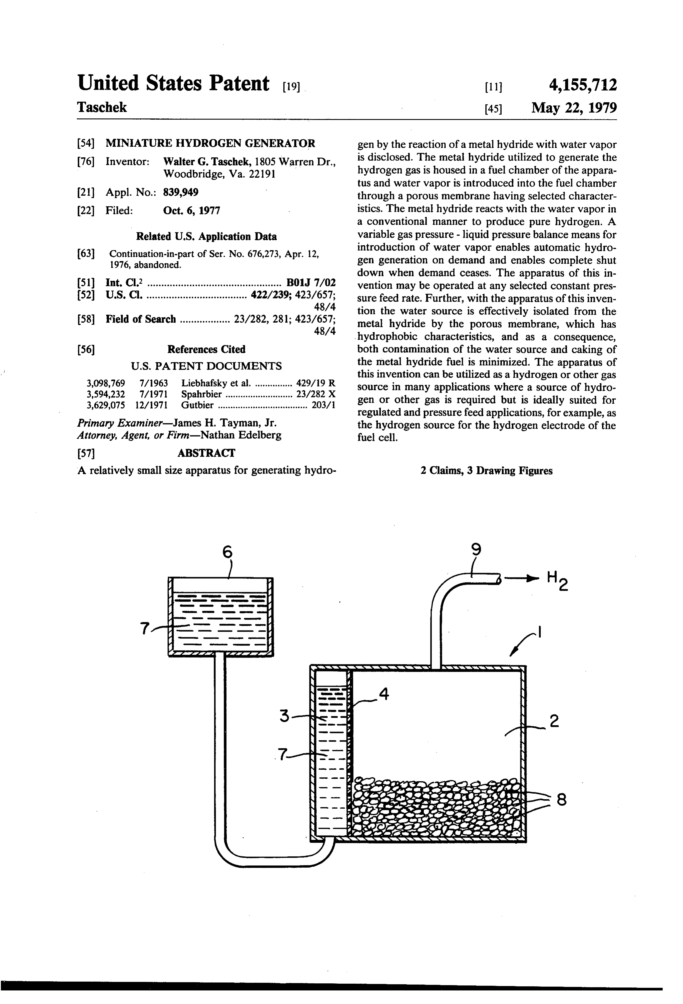
United States Patent (19) 11 4,155,712 Taschek 45) May 22, 1979 54 MINIATURE HYDROGEN GENERATOR gen by the reaction of a metal hydride with water vapor 76) Inventor: Walter G. Taschek, 1805 Warren Dr., is disclosed. The metal hydride utilized to generate the Woodbridge, Va. 22191 hydrogen gas is housed in a fuel chamber of the appara tus and water vapor is introduced into the fuel chamber (21) Appl. No.: 839,949 through a porous membrane having selected character 22) Filed: Oct. 6, 1977 istics. The metal hydride reacts with the water vapor in a conventional manner to produce pure hydrogen. A
Related U.S. Application Data variable gas pressure - liquid pressure balance means for (63) Continuation-in-part of Ser. No. 676,273, Apr. 12, introduction of water vapor enables automatic hydro 1976, abandoned. gen generation on demand and enables complete shut down when demand ceases. The apparatus of this in (51) Int. Cl’................................................ B01J 7/02 vention may be operated at any selected constant pres (52) U.S. Cl. .................................... 422/239; 423/657; sure feed rate. Further, with the apparatus of this inven 48/4 tion the water source is effectively isolated from the 58 Field of Search .................. 23/282,281; 423/657; metal hydride by the porous membrane, which has 48/4 hydrophobic characteristics, and as a consequence, (56) References Cited both contamination of the water source and caking of
this invention can be utilized as a hydrogen or other gas 3,594,232 7/1971 Spahrbier ............... 23/282 X source in many applications where a source of hydro 3,629,075 12/1971 Gutbier .................................... 203/1 gen or other gas is required but is ideally suited for regulated and pressure feed applications, for example, as
Primary Examiner-James H. Tayman, Jr. the hydrogen source for the hydrogen electrode of the Attorney, Agent, or Firm-Nathan Edelberg fuel cell.
A relatively small size apparatus for generating hydro 2 Claims, 3 Drawing Figures
an yaWXXYYaYa YaYa YaYa YaYa YaY NYSSYAYYA
Page 2
Drawing sheet — no readable text.
Page 3
reservoir by means of a specially shaped wick, which is
MINATURE HYDROGEN GENERATOR adapted for capillary action. It will be appreciated that
STATEMENT OF GOVERNMENT INTEREST
with water rather than water vapor as the primary activator, relatively quick action hydrogen gas shutoff
The invention described herein may be manufac 5 is difficult, if not impossible to attain. Moreover, the tured, used, and licensed by or for the Government for wide mouth, funnel shaped, capillary material, wick and Governmental purposes without the payment to me of the requisite lower level disposed reservoir greatly any royalties thereon. complicate a compact design of the generator for porta ble use.
COPENDING APPLICATION STATEMENT 10 As another example of the prior act, the hydrogen This application is a continuation in part of my co generator disclosed in U.S. Pat. No. 3,133,837 also uti pending application Ser. No. 676,273, filed Apr. 12, lizes water as the principal activator and utilizes an 1976 now abandoned. additional element, a pressure controlled pump means
BACKGROUND OF THE INVENTION
to automatically introduce water to the metal hydride, 15 as required. It will be appreciated that the disadvan
This invention relates to hydrogen generators, and tages of the first described prior art device are present in more particularly, to a miniature hydrogen generator. the latter prior art device, as well. There are many applications where a source of hy SUMMARY OF THE INVENTIONS drogen is required. In field applications, the most com mon source of hydrogen utilized today is the well 20 This invention provides a small portable hydrogen known bottles or tanks in which the hydrogen is stored generator utilizing a metal hydride and water vapor in under pressure. It will be appreciated that these hydro which hydrogen can be automatically produced on gen tanks or bottles are generally bulky and rather demand or at a constant pressure feed over widely vary heavy. Further, when a tank or bottle is exhausted it ing hydrogen demand rates without water supply con must be replaced with another tank or bottle. Storage 25 tamination or metal hydride caking complications. tanks or bottles are utilized in field applications because BRIEF DESCRIPTION OF THE DRAWING heretofore hydrogen production facilities have been considered too large, too heavy, too expensive and in A full and complete understanding of the invention many instances, too unsafe, for portable operation. can be obtained from the following detailed description Commonly, the hydrogen is generated at a hydrogen 30 of the invention when read in conjunction with the production plant and is pumped into the tanks or bottles annexed drawing in which:
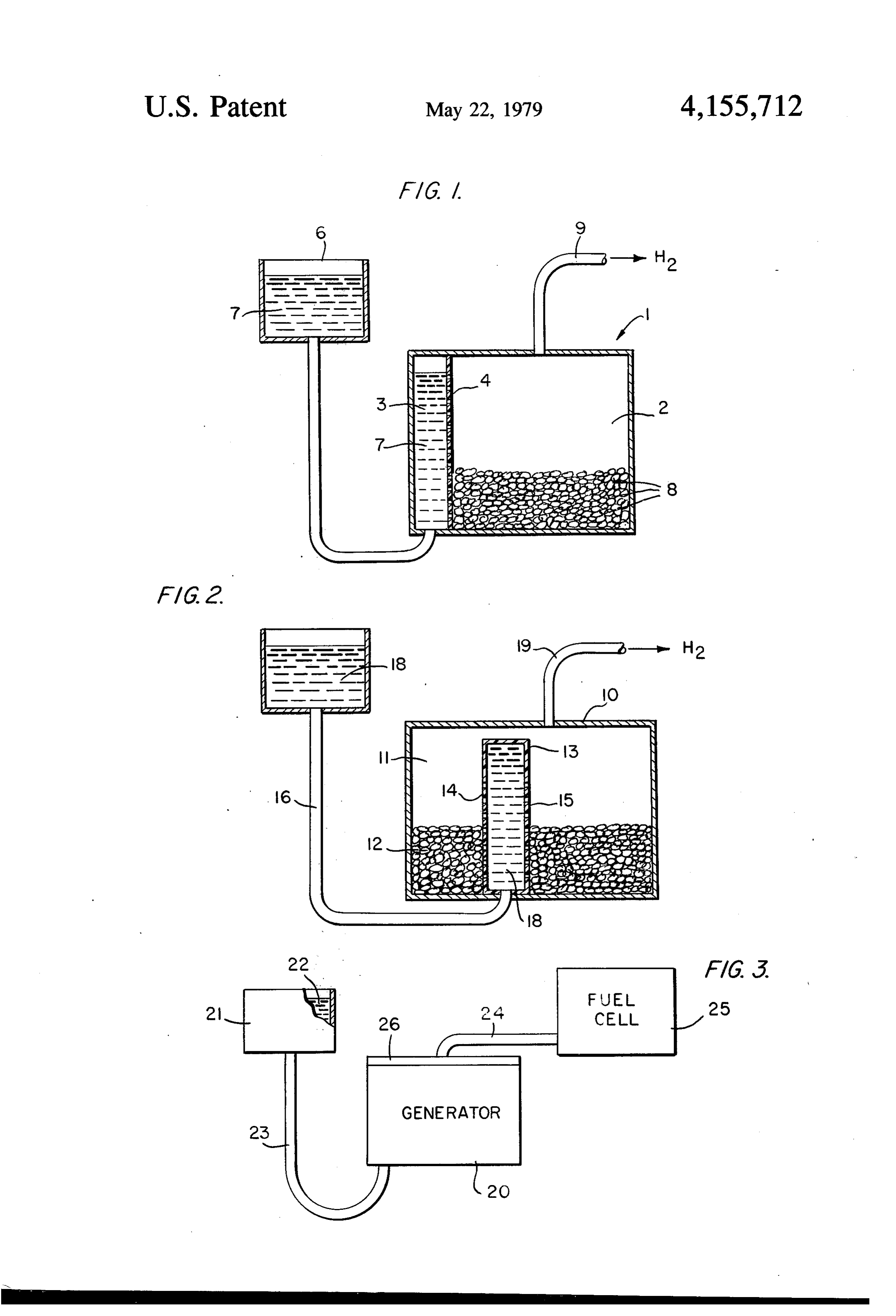
under pressure. FIG. 1 shows a first embodiment of a hydrogen gen There are, of course, many different known ways of erator constructed in accordance with this invention; generating hydrogen. One well-known method of gen FIG. 2 shows a second embodiment of a hydrogen erating hydrogen is to react a metal hydride such as 35 generator constructed in accordance with this inven lithium hydride (Li H) with water or water vapor. tion; and
When the metal hydride chemically reacts with water FIG. 3 shows a fuel cell and a hydrogen generator of or water vapor, hydrogen gas is released from the hy this invention coupled to the fuel cell. dride. It is recognized that prior art portable hydrogen DETAILED DESCRIPTION OF THE generators have not been widely utilized largely due to INVENTION hydride fuel caking if water is applied directly or if the amount of water vapor introduced is not adequately In both disclosed embodiments, FIG. 1 and FIG. 2, a controlled. Further, where the metal is a Group 1A metal hydride 8 is stored in a fuel compartment 2 into metal such as L1, Na or K (as is often the case), the which water vapor is introduced from a water compart reaction with a liquid water often forms caustic (Lye) 45 ment 3a. The water compartment 3a is separated from solutions, i.e., NaOH, KOH, LiOH which may cause the fuel compartment 2 by means of a porous membrane various malfunctions and greatly reduce the lifetime of having selected characteristics that permit water vapor the portable hydrogen generator, especially in intermit but not water in liquid form, to enter the fuel compart tent use, unattended applications. Moreover, prior art ment 2. In both embodiments the water vapor chemi generators generally do not provide a regulated source 50 cally reacts with the metal hydride to produce hydro of hydrogen in which the hydrogen can be automati gen in a conventional manner. To enable the automatic cally shut off and generated on demand over widely introduction of water vapor, water is stored in a first varying hydrogen demand rates with quick response to water compartment and the compartment 3a is coupled change in demand. to a second water compartment 3b by means of a hollow Several hydrogen generators are known which are 55 hose 5, or the like, which readily permits water move intended for use in fuel cell applications but use of these ment there through. In both embodiments, the hydro prior art generators in portable applications may not be gen generated in the compartment 2 containing the feasible in many instances. For example the hydrogen metal hydride 8 may be directly transmitted by gas line generator disclosed in U.S. Pat. No. 3,649,360 to to any device which utilizes hydrogen, for example, a Bloomfield is intended for use in fuel cell applications. fuel cell. Both hydrogen generators embodiments may This prior art device is a self contained system which be relatively small in size, light in weight, and may be utilizes both water and water vapor to activate the readily transported from place to place. metal hydride bed to produce hydrogen gas. In this Referring to the drawing, and particularly to FIG. 1, prior art device the metal hydride is subject to caking as a container or housing 1 shown in cross-section in the the principal electrochemical activator is water. In this 65 drawing has a fuel compartment 2 and water compart prior art device, water vapor, which is a byproduct of ments 3a and 3b, Fuel compartment 2 and water com the fuel cell electrochemical reaction, is provided partment 3a are separated by means of a porous hydro merely as a supplemental means from a gravity fed phobic membrane 4 which is also shown in cross-sec
Page 4
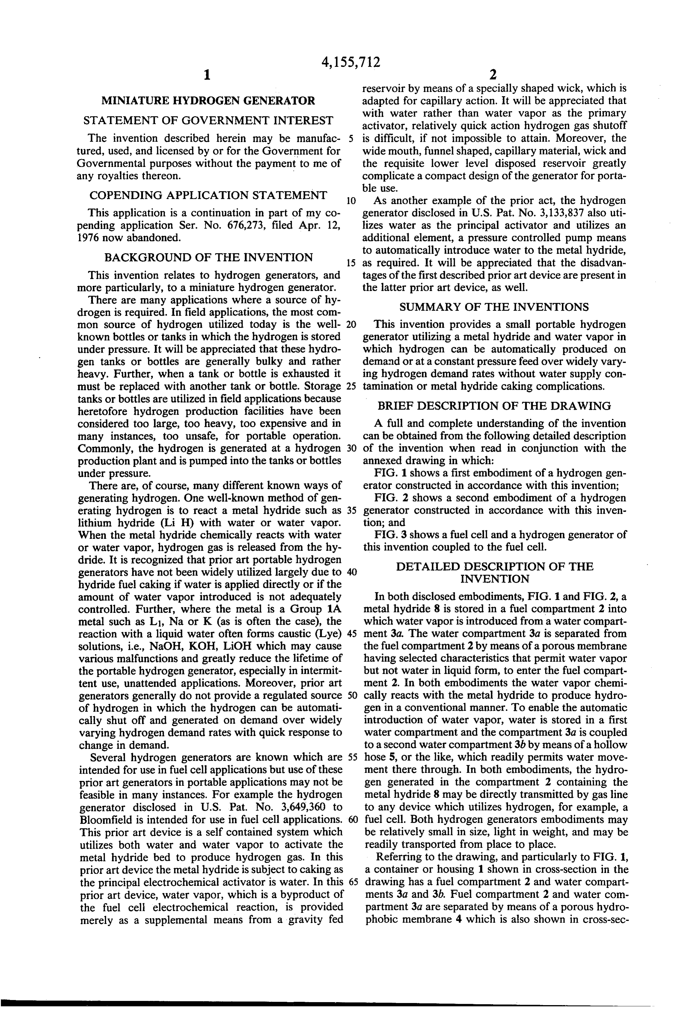
tion in FIG. 1. As mentioned heretofore, the porous minum hydride (LiAlH4). The reactions of these two membrane 4 must permit passage of water vapor but metal hydrides with water are as follows: must not permit passage of water, perse, in liquid form.
It has been found that hydrophobic meterials which possess these pass-no pass characteristics, with a rela tively low pressure differential (i.e.--0.1 psi) across the material, are commercially available with selected po If excess water is present (as in most prior art genera rosity, pore size and material thickness. For example, tors) the reaction is porous "Teflon', commercially available from Chem plast, Inc., and advertized in 1975 and later, Filteration 10
Engineering catalogs as "Zitex' i846B122, 5 mils thickness; #E606-122, 19 mils thickness, may be utilized It will be noted that water disposal requirements are as the porous membrane 4 in this invention when the doubled if excess water is present. Moreover, it has been passage of water vapor and the nonpassage of water is found that Ca(OH)2 is not very soluble, but forms a the requirement in a particular gas generation applica 15 paste with excess water. Obviously, excess water in the tion. gas generation phase is highly undesirable. The present As a general membrane 4 consideration, porosity, is invention which relies solely on water vapor for the not a major material selection consideration within metal hydride reaction minimizes the potential for ex reasonable porosity limits. It will be appreciated that cess water problems.
porosity increases diffusion of vapor through the mem 20 From the foregoing reaction equations it is apparent brane. Porosities of 40 to 75 percent have been found to that calcium hydride and lithium aluminum hydride be acceptable in some water, water vapor embodiments both give off pure hydrogen when these hydrides react of this invention. with water vapor.
It has been found, however, that pore size affects the 25 As previously mentioned, water 7 flows from water liquid bubble pressure characteristic and that this affects storage compartment 3b into water compartment 3a by the pressure differential required to initiate flow of means of hose or conduit 5, as long as pressure inside liquid through the membrane. In this invention, bubble fuel compartment 2 is less than the pressure in water pressure at least 0.1 psi is involved and higher bubble compartment 3a. Water in the form of vapor will flow pressure is preferred. In a typical case, material with a from water compartment 3a into fuel compartment 2 at bubble pressure characteristic over 0.5 psi might be 30 a rate proportional to the liquid water level in water utilized. compartment 3a. This water vapor will react with the The thickness of the porous membrane has been metal hydride fuel 8 and hydrogen (H2) will be gener found to have a relatively small effect on vapor diffu ated. The generated hydrogen will flow out of fuel sion, as well. Of course, the greater the thickness, the compartment 2 through the hose or conduit 9. greater the resistance to passage of the water vapor. 35 The other end of hose or conduit 9 will normally be Container 1 may be constructed from plastic, metal or connected to a device not shown in FIG. 1, that utilizes any other suitable material that is inert to hydrogen and the hydrogen generated in fuel compartment 2. For to the metal hydride fuel 8 which is located in fuel example, as previously stated, hose or conduit 9 may be compartment 2. Hydrogen is withdrawn from fuel com connected to a hydrogen utilizing fuel cell device. partment 2 of container 1 by means of the hose or con 40 For purpose of operational discussion, it is assumed duit 9 which may be constructed of like hydrogen inert that hose on conduit 9 is connected to a conventional material. hydrogen utilizing device, not shown in FIG. 1, that Likewise, the compartment 3b which serves as a requires hydrogen on an intermittent or noncontinuous reservoir in this invention may be constructed from basis.
plastic metal or other suitable material. In this case, of 45 If the hydrogen utilization device suddenly demands course, the material must not be adversely affected by more hydrogen, the gas pressure in both the compart the contained liquid. It will be appreciated hereinafter ment 2, and the compartment 3a, which is substantially that the volume of the liquid and the disposition of the equal to start, will drop, with the greatest drop occur compartment 3b relative to the container 1 provides a 50 ring first in compartment 2, causing the water in the head pressure factor which is utilized when balanced water compartment 3b to flow into compartment 3a to against the increased gas pressure in compartments 2 compensate for the gas pressure differential. As water and 3a when gas demand ceases to move the liquid out indicated at 7, flows into compartment 3a, more of the of the compartment 3a. This head pressure will decline porous membrane 4 surface will be exposed to water as as the volume of the liquid declines with vapor utiliza 55 the water rises in compartment 3a increasing the diffu tion in the metal hydride gas generation reaction. To sion of water vapor into the fuel chamber 2, thereby replenish the volume of liquid in the liquid reservoir increasing the water vapor-metal hydride reaction and, compartment 3b it may be desirable in some applica thus, the hydrogen production rate. Typically, it has tions to provide a level controlled liquid input means as been found, there is a slight delay between hydrogen indicated at 6. Obviously, almost any level control 60 demand and production-resulting in an excess produc means, such as found in a bathroom commode water tion rate for a short period, i.e., until the pressure and closet, may be utilized for this liquid replenishing pur water level stabilize for the increased rate. The same pose. For purposes of simplicity in the drawing, the pattern follows in reverse for a drop in hydrogen de level control means is illustrated in block diagram form mand. There is no excess production, of course, in the
Metal hydride fuel 8 can be any suitable metal hy 65 case of a drop in demand.
When the hydrogen utilization device goes into a dride that freely gives off pure hydrogen (H2) when nonconsuming mode, the gas pressure in compartment 2 exposed to water (H2O) - vapor. Two suitable metal and in compartment3a will increase forcing water com hydrides are calcium hydride (Cah) and Lithium alu
Page 5
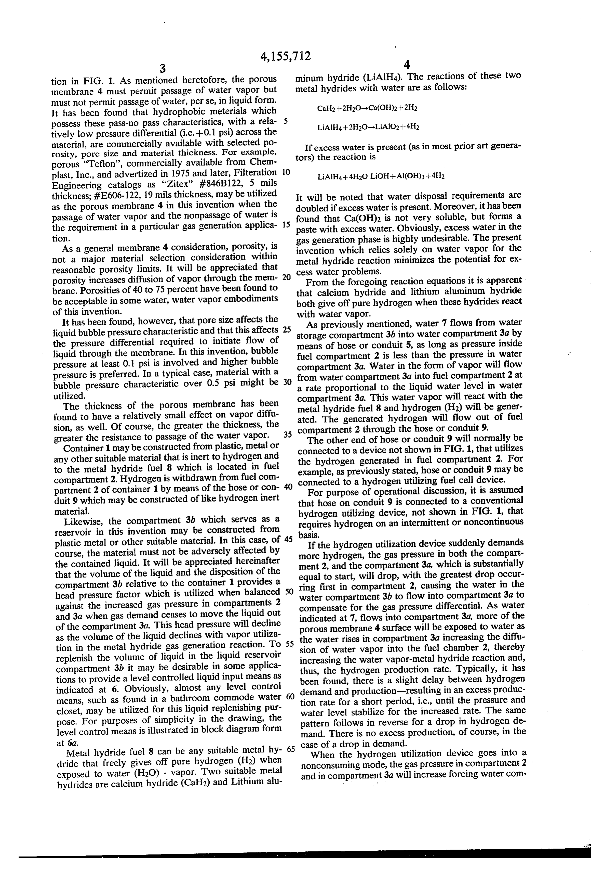
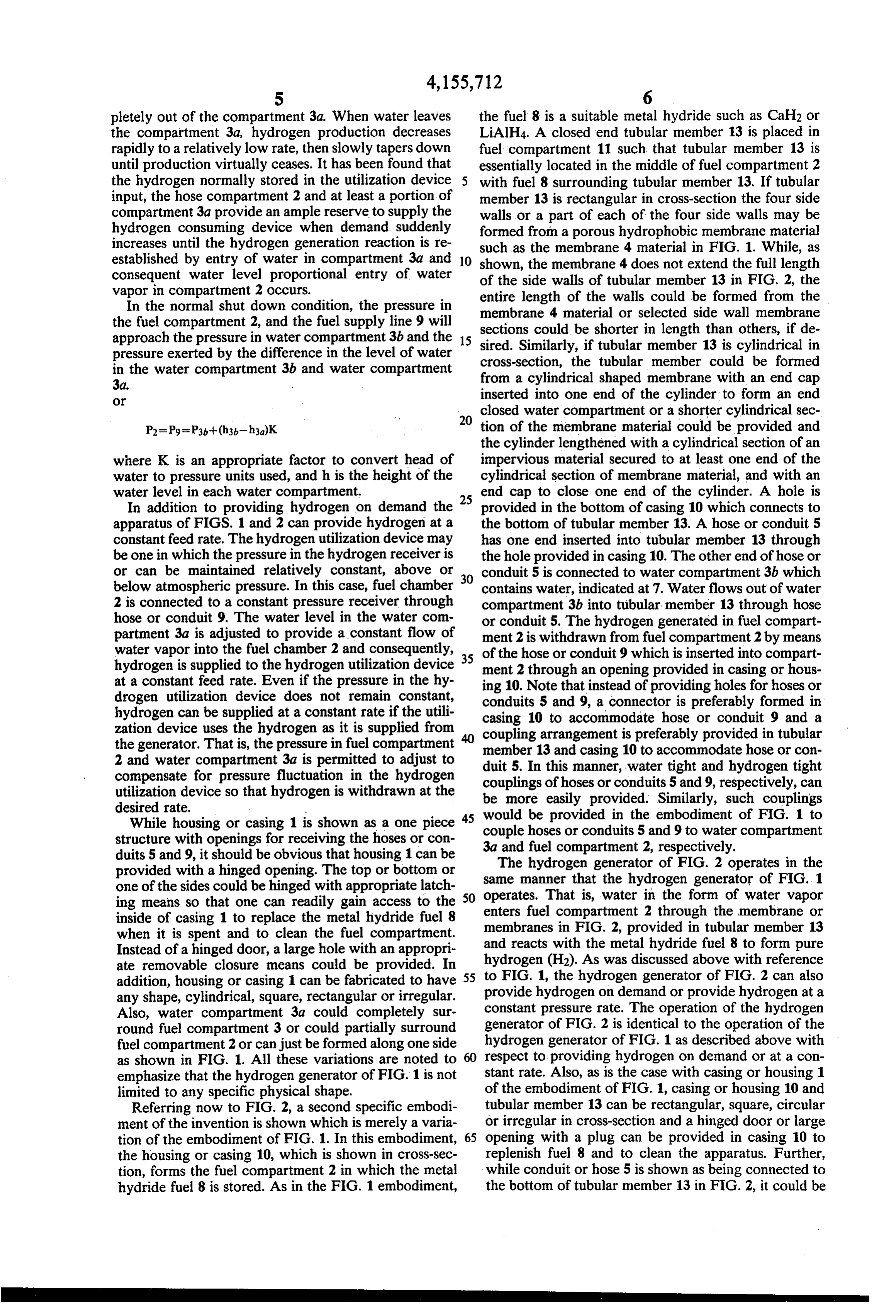
pletely out of the compartment 3a. When water leaves the fuel 8 is a suitable metal hydride such as Calh2 or the compartment 3a, hydrogen production decreases LiAlH4. A closed end tubular member 13 is placed in rapidly to a relatively low rate, then slowly tapers down fuel compartment 11 such that tubular member 13 is until production virtually ceases. It has been found that essentially located in the middle of fuel compartment 2 the hydrogen normally stored in the utilization device 5 with fuel 8 surrounding tubular member 13. If tubular input, the hose compartment 2 and at least a portion of member 13 is rectangular in cross-section the four side compartment3a provide an ample reserve to supply the walls or a part of each of the four side walls may be hydrogen consuming device when demand suddenly formed from a porous hydrophobic membrane material increases until the hydrogen generation reaction is re such as the membrane 4 material in FIG. 1. While, as established by entry of water in compartment 3a and 10 shown, the membrane 4 does not extend the full length consequent water level proportional entry of water of the side walls of tubular member 13 in FIG. 2, the vapor in compartment 2 occurs.
In the normal shut down condition, the pressure in entire length of the walls could be formed from the membrane 4 material or selected side wall membrane the fuel compartment 2, and the fuel supply line 9 will sections could be shorter in length than others, if de approach the pressure in water compartment 3b and the 15 sired. Similarly, if tubular member 13 is cylindrical in pressure exerted by the difference in the level of water cross-section, the tubular member could be formed in the water compartment 3b and water compartment from a cylindrical shaped membrane with an end cap
O inserted into one end of the cylinder to form an end
closed water compartment or a shorter cylindrical sec tion of the membrane material could be provided and the cylinder lengthened with a cylindrical section of an where K is an appropriate factor to convert head of impervious material secured to at least one end of the water to pressure units used, and h is the height of the cylindrical section of membrane material, and with an water level in each water compartment. end cap to close one end of the cylinder. A hole is In addition to providing hydrogen on demand the 25 provided in the bottom of casing 10 which connects to apparatus of FIGS. 1 and 2 can provide hydrogen at a the bottom of tubular member 13. A hose or conduit 5 constant feed rate. The hydrogen utilization device may has one end inserted into tubular member 13 through be one in which the pressure in the hydrogen receiver is the hole provided in casing 10. The other end of hose or or can be maintained relatively constant, above or conduit 5 is connected to water compartment 3b which below atmospheric pressure. In this case, fuel chamber contains water, indicated at 7. Water flows out of water 2 is connected to a constant pressure receiver through compartment 3b into tubular member 13 through hose hose or conduit 9. The water level in the water com or conduit 5. The hydrogen generated in fuel compart partment 3a is adjusted to provide a constant flow of ment 2 is withdrawn from fuel compartment 2 by means water vapor into the fuel chamber 2 and consequently, 35 of the hose or conduit 9 which is inserted into compart hydrogen is supplied to the hydrogen utilization device ment 2 through an opening provided in casing or hous at a constant feed rate. Even if the pressure in the hy ing 10. Note that instead of providing holes for hoses or drogen utilization device does not remain constant, conduits 5 and 9, a connector is preferably formed in hydrogen can be supplied at a constant rate if the utili zation device uses the hydrogen as it is supplied from casing 10 to accommodate hose or conduit 9 and a the generator. That is, the pressure in fuel compartment member 13arrangement coupling is preferably provided in tubular 2 and water compartment 3a is permitted to adjust to duit 5. In this manner, 10water and casing to accommodate hose or con compensate for pressure fluctuation in the hydrogen couplings of hoses or conduits tight 5 and and hydrogen tight 9, respectively, can utilization device so that hydrogen is withdrawn at the be more easily provided. Similarly, such couplings desired rate.
would be provided in the embodiment of FIG. 1 to
While housing or casing 1 is shown as a one piece 45 couple structure with openings for receiving the hoses or con 3a and hoses or conduits 5 and 9 to water compartment fuel compartment 2, respectively.
duits 5 and 9, it should be obvious that housing 1 can be The hydrogen generator of FIG. 2 operates in the provided with a hinged opening. The top or bottom or one of the sides could be hinged with appropriate latch SO same manner that the hydrogen generator of FIG. 1 ing means so that one can readily gain access to the enters fuelThat operates. is, water in the form of water vapor inside of casing 1 to replace the metal hydride fuel 8 membranes compartment 2 through the membrane or when it is spent and to clean the fuel compartment. and reacts with the metal hydridein fuel in FIG. 2, provided tubular member 13
Instead of a hinged door, a large hole with an appropri hydrogen (H2). As was discussed above 8with to form pure reference ate removable closure means could be provided. In addition, housing or casing 1 can be fabricated to have 55 to FIG. 1, the hydrogen generator of FIG. 2 can also any shape, cylindrical, square, rectangular or irregular. provide hydrogen on demand or provide hydrogen at a Also, water compartment 3a could completely sur constant pressure rate. The operation of the hydrogen round fuel compartment 3 or could partially surround generator of FIG. 2 is identical to the operation of the fuel compartment 2 or can just be formed along one side hydrogen generator of FIG. 1 as described above with as shown in FIG. 1. All these variations are noted to respect to providing hydrogen on demand or at a con emphasize that the hydrogen generator of FIG. 1 is not stant rate. Also, as is the case with casing or housing 1 limited to any specific physical shape, of the embodiment of FIG. 1, casing or housing 10 and Referring now to FIG. 2, a second specific embodi tubular member 13 can be rectangular, square, circular ment of the invention is shown which is merely a varia or irregular in cross-section and a hinged door or large tion of the embodiment of FIG. 1. In this embodiment, 65 opening with a plug can be provided in casing 10 to the housing or casing 10, which is shown in cross-sec replenish fuel 8 and to clean the apparatus. Further, tion, forms the fuel compartment 2 in which the metal while conduit or hose 5 is shown as being connected to hydride fuel 8 is stored. As in the FIG. 1 embodiment, the bottom of tubular member 13 in FIG. 2, it could be
Page 6
connected to the top of tubular member 13. Similarly, For example, the principles outlined above with re hose or conduit 5 of FIG. 1 can be connected to the top spect to a water activated metal hydride generator can of water compartment 3a rather than the bottom as be extended to other systems where the principle reac shown in FIG.1. Also, hose or conduit 9 in FIGS. 1 and tants are a non water liquid and an appropriate chemi 2 can communicate with fuel chamber 2 at any point. cally reactive material which produces another gas The apparatus of FIGS. 1 and 2 can each be fabricated when combined with a vapor. The liquid may also be a as a small light weight package with all the components, mixture or solution. It will be appreciated that all liq uids, to different degrees, exhibit a vapor pressure including the hydrogen utilization device, housed in a which would allow transpiration of the vapor through single container or package. Under such conditions, the 10 the porous hoses or conduits, 5 and 9 could be and normally would membrane while holding the liquid. (1) For be replaced by couplers or connectors as should be example, a salt solution would allow water vapor obvious. Thus, while the elements 5 and 9 of FIGS. 1 through but hold the salt and liquid water back; (2) if calcium carbide is the fuel the device could be used to and 2 have been defined above as hoses or conduits, control acetylene production; or (3) the liquid could be these elements are to be considered in the broader sense 15 Bromine and the device used to control reaction of as being any type of suitable coupling arrangement that some desired component.
provides communication between the water storage What is claimed is:
compartment and the water compartment adjacent the 1. An automatic, demand responsive gas generator fuel compartment and between the fuel compartment for producing gas by chemical reaction of a solid fuel and the hydrogen utilization device. 20 upon controlled exposure to a liquid vapor, said genera Referring to FIG. 3, FIG. 3 is presented to show a tor comprising:
typical use of a hydrogen generator of this invention. a compartment for storing solid fuel; As shown in FIG. 3, the hydrogen generator comprises a first compartment adapted to contain a liquid such a housing or casing 20 in which hydrogen is generated as water;
by the reaction of water vapor with a metal hydride fuel 25 a wall common to said fuel compartment and said as described above with reference to FIGS. 1 and 2. liquid compartment, said wall including a porous Housing 20 can be either housing 10 of FIG. 2 or hous hydrophobic membrane of Teflon material of a ing 1 of FIG. 1. A removable sealed lid 26 is provided selected wall thickness adapted to pass gaseous and in the top of housing 20. The water 22 stored in water vaporous mediums and compartment 3b is transmitted to the water compart 30 to restrict free passage of said liquid; ment 3a in housing 20 by means of the hose or conduit a second compartment adapted to contain a second 5. The hydrogen generated in the fuel compartment of portion of said liquid;
housing 20 is transmitted to the hydrogen electrode or a a hollow tubular means interconnecting said first and fuel cell 25. The entire apparatus of FIG. 3 can be fabri second liquid compartments; cated as a small package to form a small light weight 35 said second liquid compartment being disposed above portable DC power supply. As mentioned above, if the said first liquid compartment such that the mass of apparatus of FIG. 3 were fabricated as a small package, liquid in said second compartment exerts a head elements 23 and 24 would be short conventional cou pressure on said first liquid compartment; and a gas outlet connected to said fuel compartment for plers. Of course, elements 23 and 24 could also be very conducting produced gas to a gas utilization means short sections of hose or conduit. The DC voltage sup whereby the gas utilization causes a decrease in gas plied by the fuel cell 25 can be used with, for example, pressure in the fuel compartment and the first liq airport runway lights, warning light systems along uid compartment which causes liquid to flow from highway construction and the like or wherever a low said second liquid compartment into said first liq voltage DC supply is needed. 45 uid compartment and increases the liquid vapor While the invention has been described with refer diffusion into the fuel compartment thereby in ence to two specific embodiments illustrated in FIGS. 1 creasing the gas production rate. - and 2, it will be obvious to those skilled in the art that 2. An automatic, demand responsive, gas generator as various changes and modifications, in addition to those defined in claim 1 wherein said selected wall thickness specifically mentioned, can be made to the two embodi- 50 of said porous membrane is in the general 5 to 19 mils ments described and shown without departing from the region and the bubble pressure characteristic of the spirit and scope of the invention as set forth in the porous membrane material k k is atis least
claims.
Provenance
- Collection
- Cited prior art
- Original PDF
- patentimages.storage.googleapis.com →
- Filed
- 1977-10-06
- Pages
- 6
- Method
- pdftotext (the PDF's own text layer) + pdftoppm 300dpi page scans
- Source
- Google Patents bibliographic record
- Granted
- 1979-05-22
- Inventors
- Walter G. Taschek
- Transcribed from
- patentimages.storage.googleapis.com →