patent · US4744667
Microspectrofluorimeter
17 May 1988
Page 1 — bibliographic record
United States Patent (19) 11) Patent Number: 4,744,667 Fay et al. 45 Date of Patent: May 17, 1988 54 MICROSPECTROFLUORIMETER FOREIGN PATENT DOCUMENTS (75 Inventors: Fredric S. Fay, Worcester; John F. 0.106721 4/1984 European Pat. Off. . Hatch, Framingham; Kevin E. O164680 12/1985 European Pat. Off. . Fogarty, Worcester; Cyril Rodgers, 101984 11/1957 Fed. Rep. of Germany ...... 350/526 Paxton, all of Mass. 2316386 10/1974 Fed. Rep. of Germany ...... 350/526
(73) Assignee: University of Massachusetts, 2532756 3/1984 France .............................. 250/458.1 Worcester, Mass. 001.0035 4/1968 Japan ................................... 350/526 (21) Appl. No.: 900,407 OTHER PUBLICATIONS Chance et al., The Review of Scientific Instruments, vol.
22) Filed: Aug. 26, 1986 42, No. 7, Jul. 1971, pp. 951-957. Zeidler, Laboratory Equipment Digest, vol. 12, No. 7,
Related U.S. Application Data Jul. 1974, pp. 48, 50-5456, 57.
63) Continuation-in-part of Ser. No. 828,766, Feb. 11, 1986, Primary Examiner-F. L. Evans abandoned. Attorney, Agent, or Firm-Hamilton, Brook, Smith & Reynolds (51) Int. Cl." ............................................. G0N 21/64 57 ABSTRACT (52) U.S. Cl. .................................... 356/417; 350/315;
350/318; 250/461.1; 356/418 An accessory is provided to convert a conventional 58) Field of Search ............... 356/301, 317, 318, 416, microscope to a microspectrofluorimeter. The acces 356/417,418, 4.19; 350/523,526, 527, 528, 315, sory includes a filter disc having bandpass filters sepa 318, 317; 250/458.1, 459. 1, 461.1, 461.2 rated by opaque segments. The filter disc is rapidly and continuously rotated to move the filter sequentially into (56) References Cited the optical path between a wideband light source and a
the sample is synchronized to the position of the filters 3,918,793 11/1975 Kraft ................................... 350/527 during rotation by means of synchronization marks on 4,125,828 11/1978 Resnicket al. ..... 250/461.2 the filter disc. The same accessory may be positioned 4,320,970 3/1982 Dowben et al. .... ... 356/317 between the sample and a detector to detect emitted 4,443,108 4/1984 Webster .............. ... 350/315 light of different frequencies. 4,573, 195 2/1986 de France ............................... 382/6 4,586,819 5/1986 Tochigi et al....................... 356/301 48 Claims, 8 Drawing Sheets
Page 2
Drawing sheet — no readable text.
Page 3
Drawing sheet — no readable text.
Page 4
Drawing sheet — no readable text.
Page 5
Drawing sheet — no readable text.
Page 6
Drawing sheet — no readable text.
Page 7
Drawing sheet — no readable text.
Page 8
Drawing sheet — no readable text.
Page 9
Drawing sheet — no readable text.
Page 10
bly. A detector such as a photomultiplier tube with
MICROSPECTROFLUORIMETER photon counter detects light from a microscopic por tion of the sample. Light detection is synchronized with
RELATED APPLICATION the position of the rotating filters. The filter assembly This is a continuation-in-part of U.S. application Ser. 5 may be positioned between the source of illumination No. 828,766, filed Feb. 11, 1986, now abandoned. and the sample in order to sequentially change the
BACKGROUND
wavelengths of the illuminating light. Alternatively, it may be positioned between the sample and the detector
In scientific research, a material can often be charac to detect different frequencies emitted from the sample. terized by the response of a fluorescent probe to radia 10 In a preferred system, the filters are driven by a vari tion. In some procedures, a sample is illuminated alter able speed continuous drive motor. Reference marks nately with light of different wavelengths and the fluo associated with the filter elements are detected to pro rescence of the sample with the different illuminating vide indications of the position and the rate of rotation wavelengths is noted. For example, the calcium ion is of the filter. A filter disc may include fan shaped filter believed to control a variety of cellular processes with 15 regions, for passing light of different passbands, sepa a high degree of spatial and temporal precision. Calcium rated by opaque regions. The opaque regions are only has been measured in single living cells with high spatial sufficiently wide to just block the light path in order to resolution utilizing a miroscope and a highly fluorescent calcium sensitive dye Fura-2. A sample to which the provide maximum duty cycle. The photon counting dye has been added is illuminated alternately with light regions passeach 20 relative to filter is begun and ended as the opaque of 340 and 380 nanometers. The free fluorescent dye pass of eachthefilter light path. The light detected with each is normalized to the speed of the fluoresces at about 500 nanometers maximally in re sponse to the 380 nanometer excitation; whereas, the filters and to the intensity of the wideband light source. A conventional microscope with photomultiplier dye associated with the calcium ion fluoresces at about tube can be quickly converted to a microspectro 500 nanometers maximally in response to the 340 nano 25 meter excitation. The concentration of calcium can then fluorimeter by means of an accessory which connects be calculated from the formula: quickly between a conventional light source and the microscope or between the microscope and the light
Cali=Kd(R-Rimin)/(Rmax-R),3 detector. The accessory includes an optical conduit 30 between a light inlet and a light outlet. An inlet connec
Where Kd is the effective dissociation constant for the tor at the inlet end of the optical conduit mates with the Fura-2-Calcium reaction, R is the ratio of fluorescent conventional microscope light source or the micro intensity at 500 nm with the 340 and 380 nm excitation, scope. An outlet connector at the outlet end of the Rmin is the limiting value of R at a calcium concentra optical conduit mate with the microscope or the detec tion of zero, Rnax is R with fully saturated calcium and 35 tor.
(3 is an optical constant for the system which is a mea A filter assembly is eccentrically mounted relative to sure of the relative quantum yield at 380 nm of the the optical conduit. It includes a filter housing and a calcium free and calcium saturated dye. filter disc within the housing. The filter disc has a plu The use of a photomultiplier tube coupled to a micro rality of filters circumferentially spaced about a filter scope to detect the fluorescent light from a microscopic axis offset from the optical conduit. The accessory in portion of a sample has provided excellent spatial and cludes a drive motor for rotating the filters about the good temporal resolution for spectrofluorimeters. The filter axis. To make the accessory adapted to a wide microscope must be further modified to provide the range of microscopes, the inlet and outlet connectors alternate light sources. One form of dual frequency light are identical to the pinned bayonet connectors typically source separates the light into monochromatic beams 45 found between light sources and microscopes. using interferance gratings and then alternately directs the monochromatic beams to the sample using a rotat BRIEF DESCRIPTION OF THE DRAWINGS ing mirror. The interference gratings are optically inef. The foregoing and other objects, features, and advan ficient and the inefficiency is exacerbated by low duty cycles of these systems. Such systems have not pro 50 tages of the invention will be apparent from the follow vided the high switching speed required for temporal ing more particular description of preferred embodi resolution in the order of typical biological or chemical ments of the invention, as illustrated in the accompany reactions or for avoiding problems due to movement ing drawings in which like reference characters refer to the same parts throughout the different views. The artifacts and the like. Further, the light sources have drawings been difficult to align and maintain and have been very 55 being are not necessarily to scale, emphasis instead expensive. placed upon illustrating the principles of the in vention.
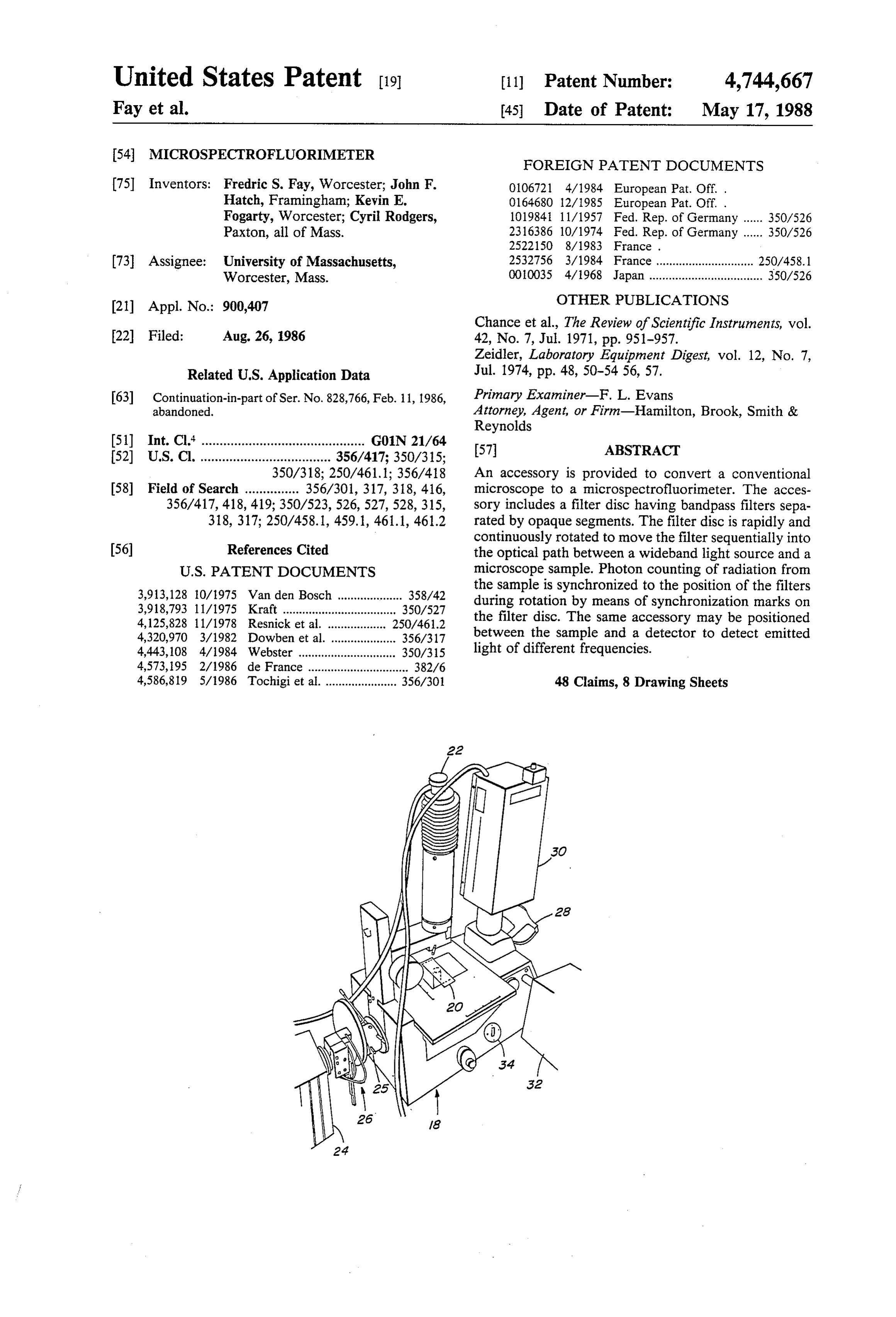
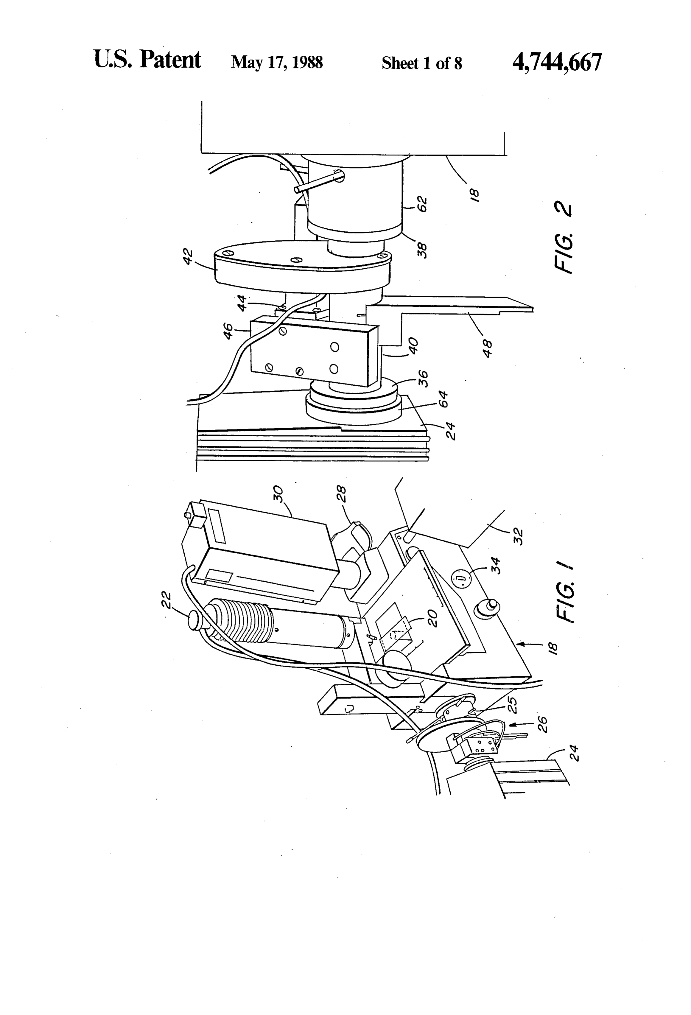
SUMMARY OF THE INVENTION FIG. 1 is a perspective view of a microspectro A microscope is adapted as a microspectrofluorime fluorimeter embodying the present invention; ter. A filter assembly is positioned in an optical path 60 FIG. 2 is an enlarged view of the filter accessory in which includes a source of illumination, a sample on the the system of FIG. 1;
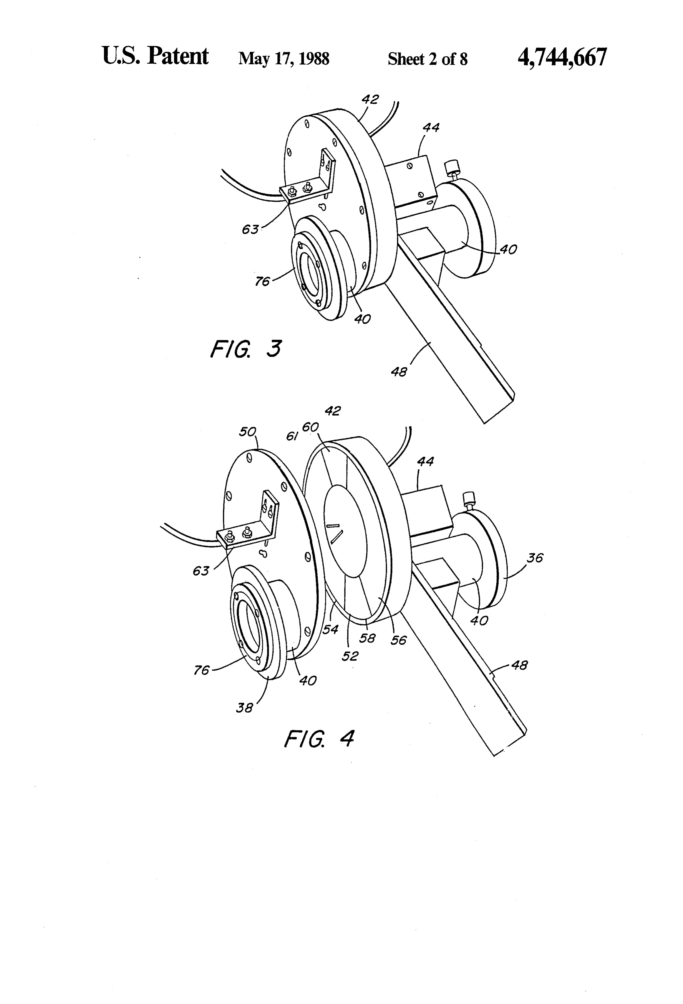
microscope and a detector. The filter assembly includes FIG. 3 is a perspective view of the filter accessory a plurality of bandpass filters having different pass removed from the system of FIG. 1 and shown from the bands which are circumferentially spaced about a filter rear of FIG. 2;
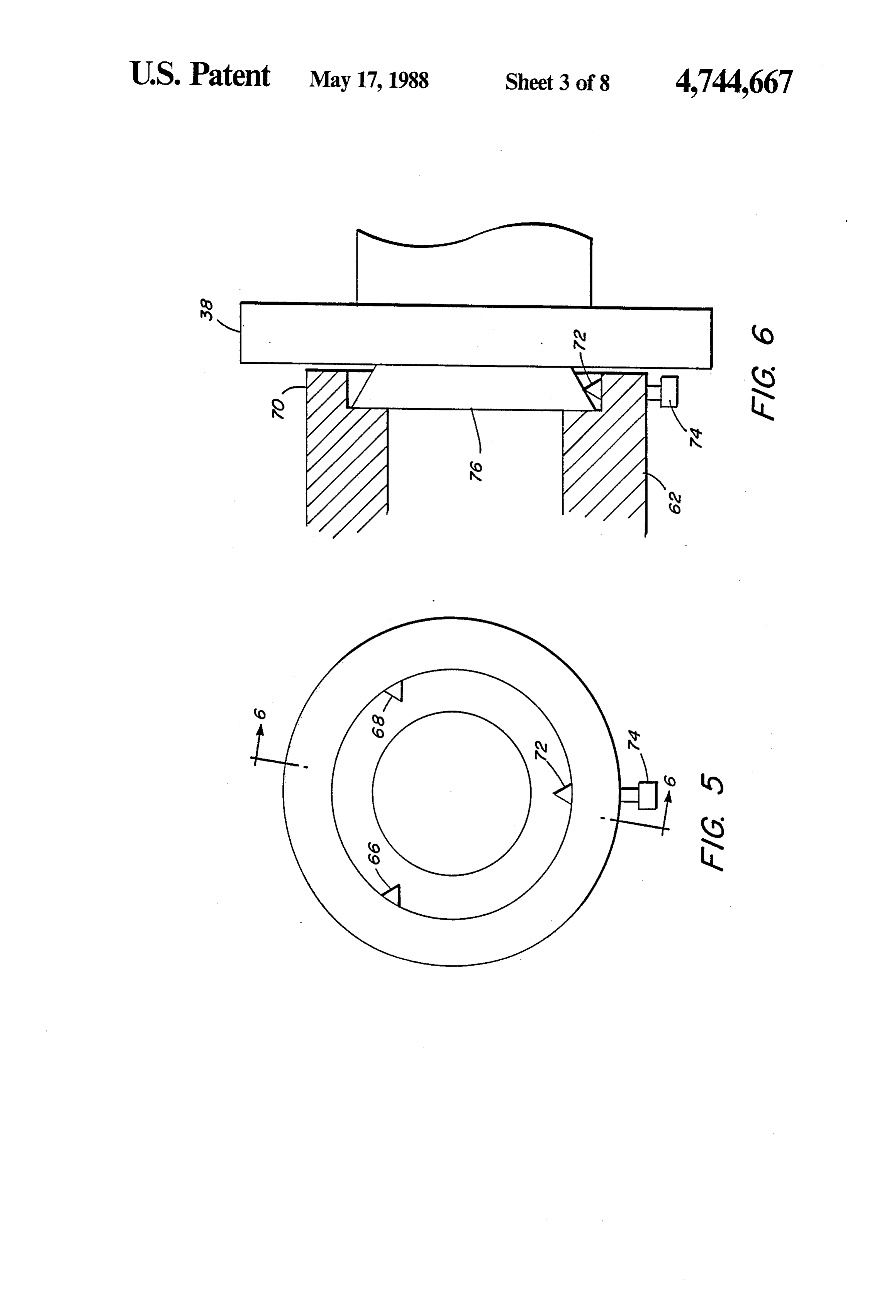
axis offset from the optical path. The filters are driven 65 FIG. 4 is a perspective view of the filter accessory of about the filter axis to sequentially move the plurality of FIG. 3 with the filter housing endcap removed; filter elements into the optical path and thus change the FIG. 5 is an end view of an element of a bayonet wavelengths of light passing through the filter assem optical connector typically mounted to a microscope;
Page 11
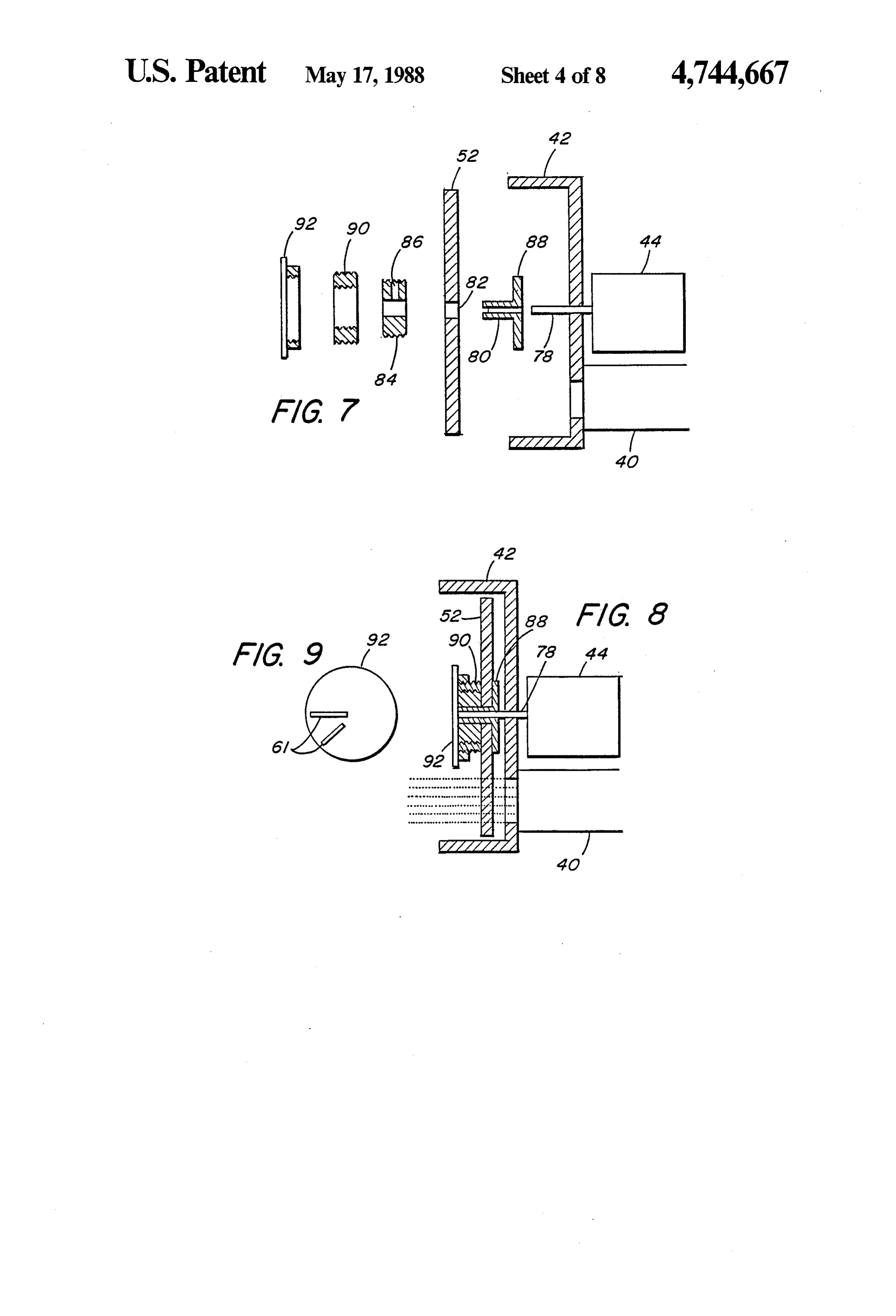
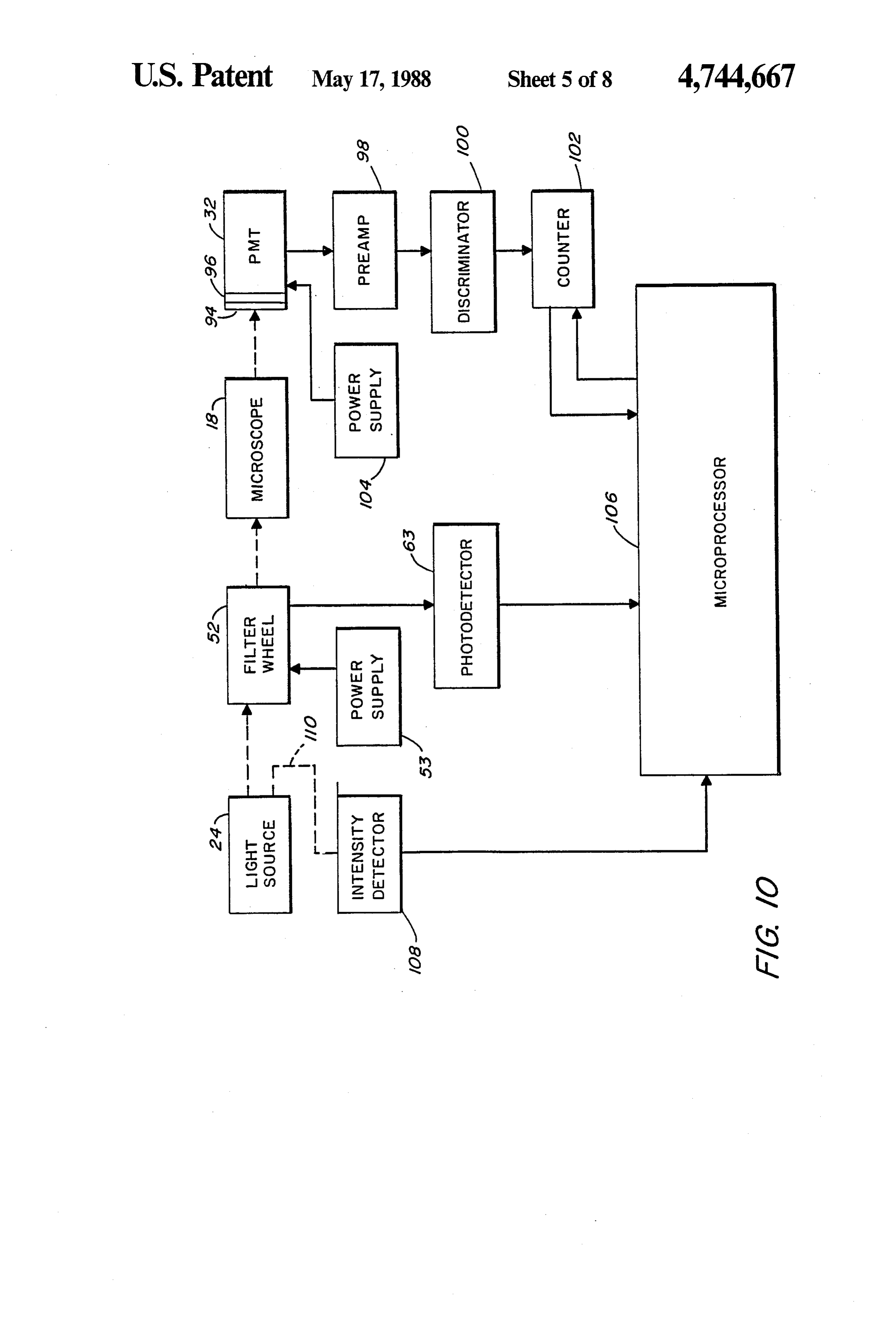
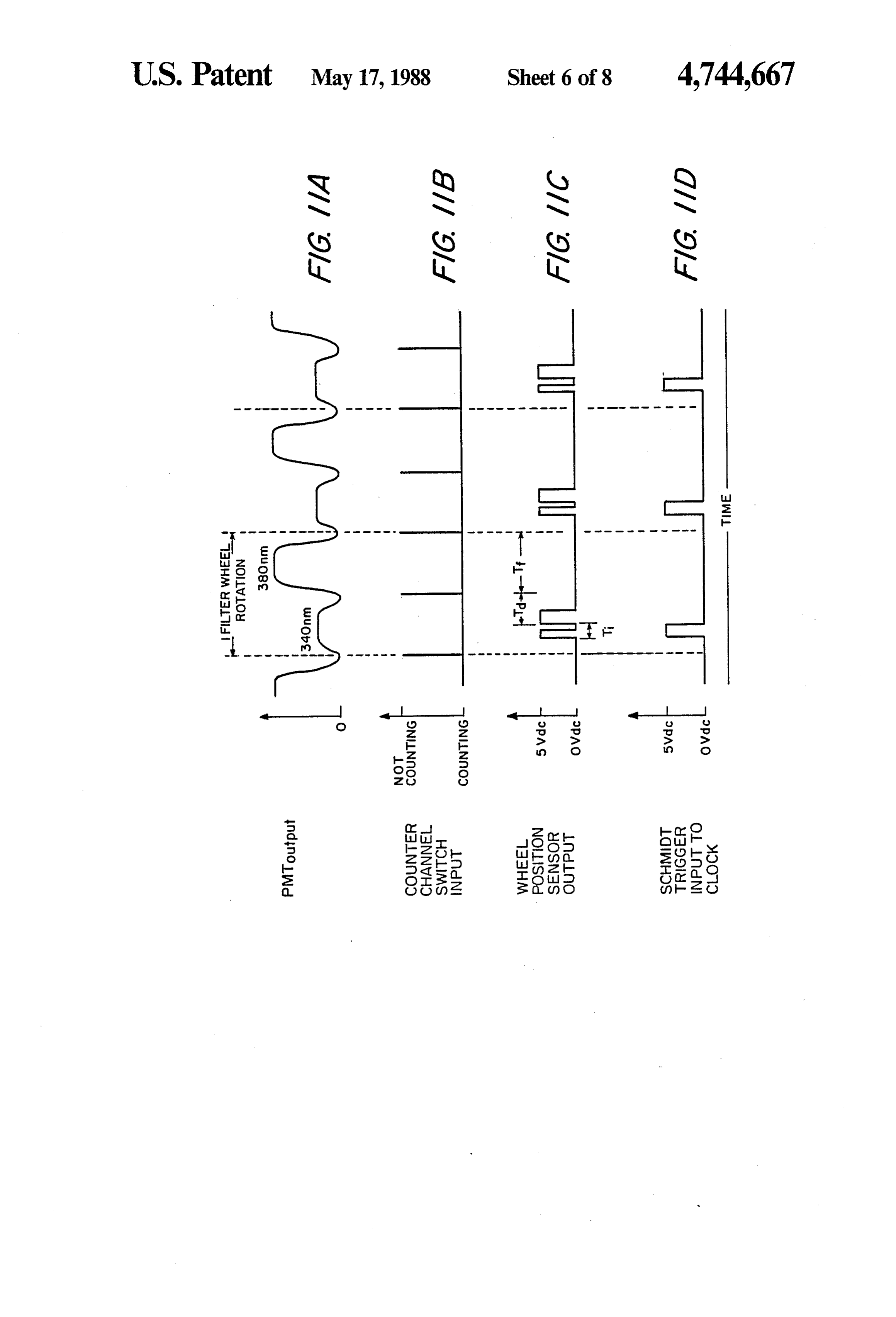
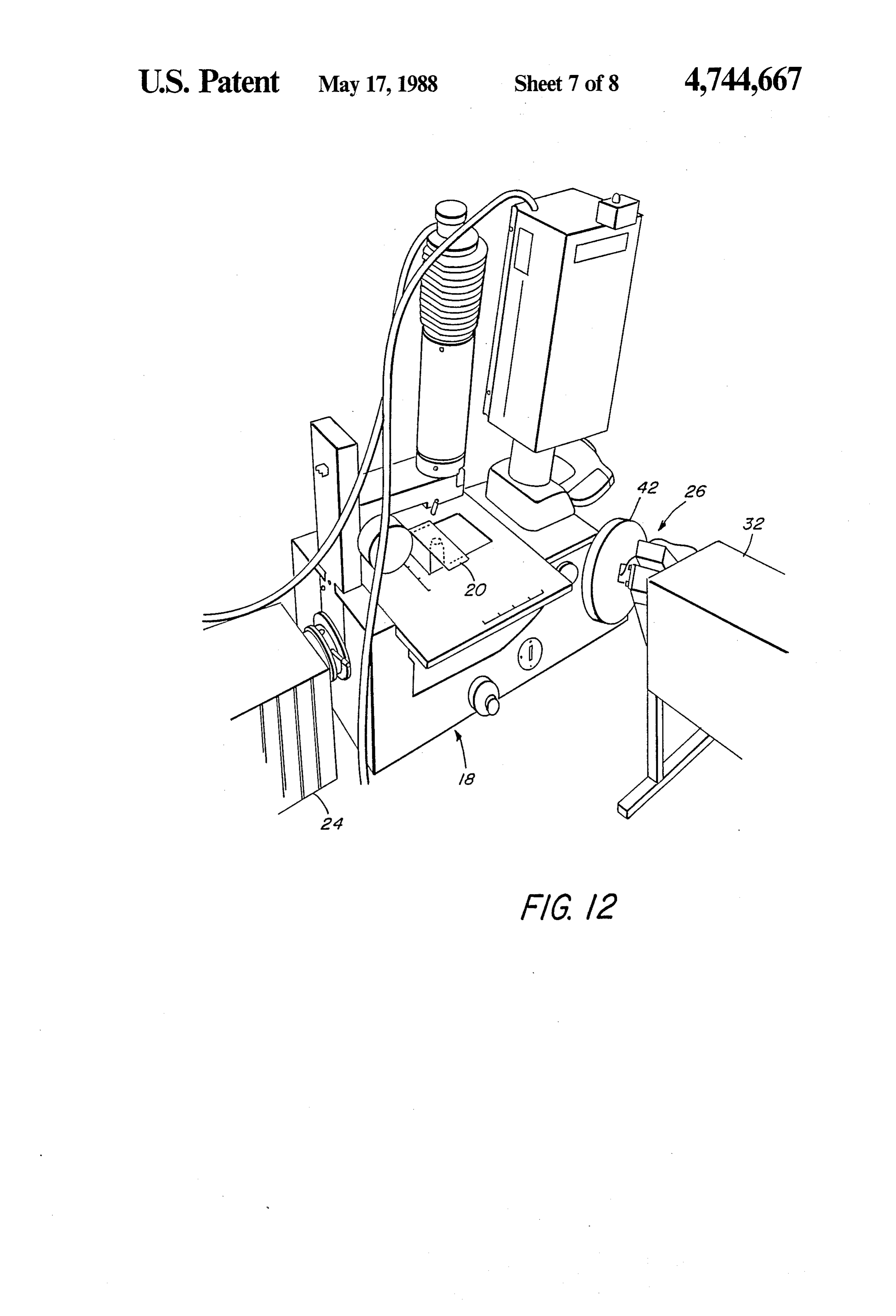
FIG. 6 is a side view, partially in section, of the bayo maximum transmission. As the filter disc is rotated by net optical connector connecting the accessory to the the motor 44, the two filters are sequentially moved into microscope; the optical path through the conduit 40. As will be FIG. 7 is an exploded sectional view of the filter discussed further below, the opaque regions 58 and 60 assembly; 5 are just wide enough to block the light beam in the FIG. 8 is a sectional view of the filter assembly; optical conduit as each is centered at the conduit. FIG. 9 is a view of the synchronizing marks on the A pair of reflective marks 61 are positioned on the filter assembly; filter assembly and those marks are sensed with each FIG. 10 is an optical and electrical block diagram of revolution of the filter disc by a light emitting diode and the microspectrofluorimeter; 10 photodetector assembly 63 mounted to the end plate 50 FIGS. 11 (A-D) are a set of timing charts for the of the housing. The signals from the photo detector microspectrofluorimeter; synchronize photon counting with rotation of the filter FIG. 12 is a perspective view of the filter assembly as will be descibed below.
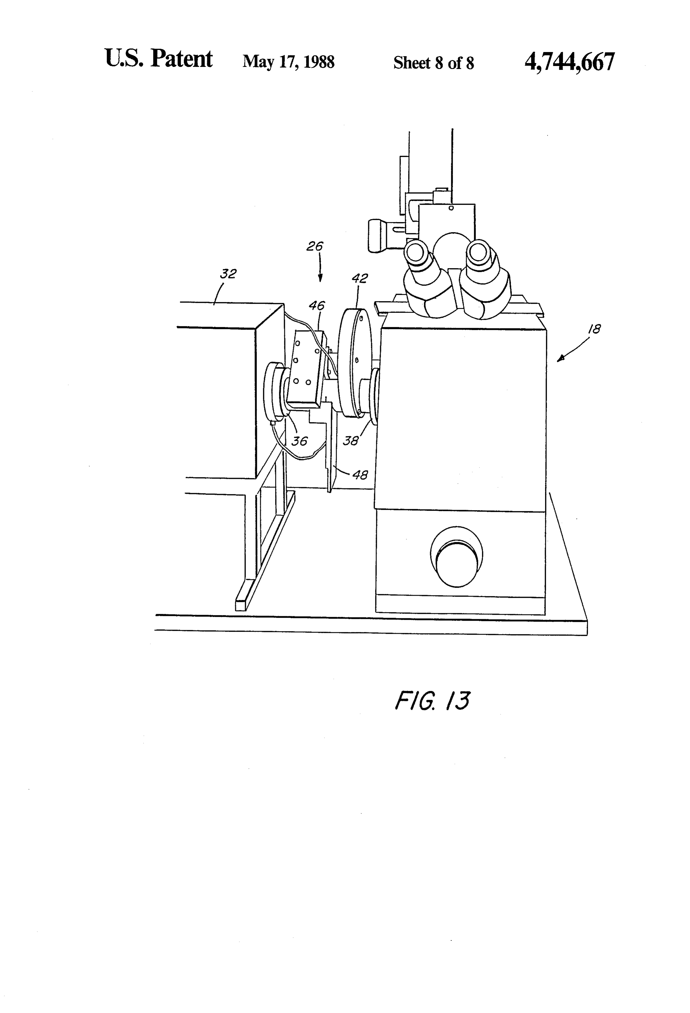
mounted in the optical path between the sample and the In order that the filter accessory can be readily detector. 15 mounted between a conventional microscope and its FIG. 13 is a rear view of the filter assembly in the conventional light source, bayonet optical connectors system of FIG. 12. 36 and 38 as illustrated in FIGS. 5 and 6 are provided.
DESCRIPTION OF A PREFERRED
FIGS. 5 and 6 actually show the female portion 62 of
EMBODIMENT the connector typically found on a microscope and the 20 male portion 38 on the accessory. The connector 64 on
A conventional microscope 18 modified in accor the xenon arc lamp would be substantially the same as dance with the present invention is illustrated in FIG. 1. the connector 38, and the conector 36 of the accessory A sample slide is shown at 20. The sample may be illu would be functionally the same as connector 62 on the minated from above by a light source 22. Alternatively, microscope housing.
a sample may be illuminated from a conventional xenon 25 As shown in FIG. 5, the female portion of the con arc lamp 24 which would typically be connected di nector includes two fixed pins 66 and 68 which extend rectly to the microscope at 25. In accordance with the radially inward from the rim 70 of the connector socket. present invention, however, a filter'assembly 26 is posi A third pin 72 is spring biased so that it can be pulled tioned in the optical path between the light source 24 outward by a pinhead 74. With the pin 72 thus pulled and the sample 20. 30 away from the socket, the frustoconical male portion of Using either light source, the specimen can be viewed the connector on the accessory 76 can be slipped behind through a binocular viewer 28, and a video output can the pins 66 and 68. When the pin 72 is then released, the be provided by a television camera 30. To provide a pin presses against the conical surface to bring the male quantitative indication of the fluorescence from a sam portion tightly into the socket. The pin can then be ple, a photomultiplier tube 32 is coupled to receive most 35 locked into place by manipulating the head 74. of the light from the sample. In a conventional micro The filter assembly is shown in greater detail in scope, a cross-hair assembly extends into the micro FIGS. 7 and 8. A drive shaft 78 extends into the housing scope housing to an image plane of the specimen from a of 42 from the drive motor 44. A filter disc carrier80 is closure 34. For the presen invention that cross-hair is positioned over the drive shaft 70. A clearance of about replaced by a variable field stop aperture which defines one mil is provided between the outer diameter of the the portion of the sample viewed by the photomultiplier carrier80 and the inner diameter of a hole 82 in the filter tube. disc 52 so that the filter can be slid onto the hub of the An enlarged view of the filter accessory is shown in carrier 80. The hub of the carrier 80 protrudes through FIG. 2. It includes the female portion 36 of a connector the filter disc and a brass retainer 84 is slid over the hub. for coupling the accessory to the xenon arc lamp 24. 45 The retainer 84 is fixed to the carrier 80 by a set screw The accessory also includes a male portion 38 of a con 86. The set screw also clamps the carrier 80, which is nector for connecting it to the microscope 18. A beam split along its length, onto the drive shaft 78. of light from the light source 24 is transmitted through The filter disc 52 is pressed snuggly against the flange an optical conduit 40 between the connectors. A filter 88 of the carrier 80 by means of an internally and exter housing 42 is eccentrically mounted relative to the opti 50 nally threaded brass sleeve 90 which is threaded onto cal conduit and houses a rotating filter disc to be de the retainer 86. The sleeve 90 is also fixed by a set scribed. The filter disc is rotated by a motor 44 which is screw. Each of the retainer 84 and sleeve 90 has a pair mounted to the optical conduit by means of a block 46. of holes in the front face thereof for tightening by a two A guide 48 is provided for a manual shutter for blocking pin wrench. Finally, an end plate 92 is positioned on the the light source from the filter assembly. 55 assembly and retained by a set screw. The end plate 92 The filter accessory removed from the microscope is is blackened as shown in FIG. 9 and carries the reflec illustrated in FIGS. 3 and 4. In these figures the acces tive synchronizing marks 61.
sory is viewed from the rear of FIG. 2. In FIG. 4 the FIG. 10 is a block diagram of the overall system by end plate 50 of the filter housing is shown removed. A which microspectrofluorimeter readings are obtained. rigid filter disc 52 is mounted within the housing for Light from the light source 24 is directed through the rotation about a center axis. The filter disc includes two rotating filter disc 52 to illuminate a sample on the mi fanshaped filter regions 54 and 56 separated by opaque croscope 18. Light emitted by the specimen in the mi regions 58 and 60 in a unitary construction. In a system croscope 18 is directed to the photomultiplier tube 32. for determining the calcium ion concentration of the The photomultiplier tube includes a bandpass filter 94 sample using Fura-2 dye, one filter has a pass band 65 which has a center frequency at 500 nanometers when centered at 340 nanometers and the other has a pass measuring calcium concentration with Fura-2. The band centered at 380 nanometers. The specific filters . filter passes the light of interest but blocks any light of used have a 10 nanometer full bandwidth at half the the excitation wavelengths which may have been re
Page 12
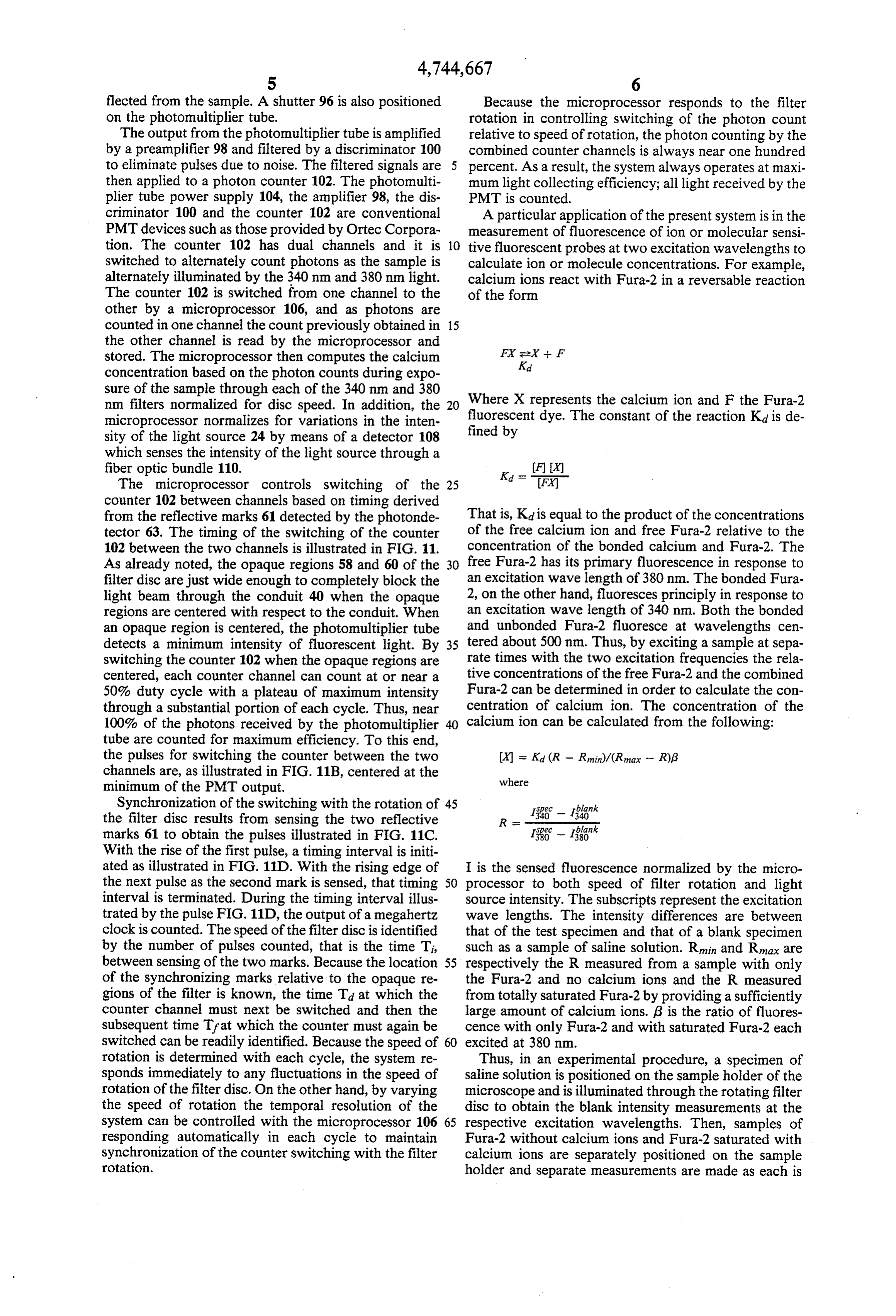
flected from the sample. A shutter 96 is also positioned Because the microprocessor responds to the filter on the photomultiplier tube. rotation in controlling switching of the photon count The output from the photomultiplier tube is amplified relative to speed of rotation, the photon counting by the by a preamplifier 98 and filtered by a discriminator 100 combined counter channels is always near one hundred to eliminate pulses due to noise. The filtered signals are percent. As a result, the system always operates at maxi then applied to a photon counter 102. The photomulti mun light collecting efficiency; all light received by the plier tube power supply 104, the amplifier 98, the dis PMT is counted.
criminator 100 and the counter 102 are conventional A particular application of the present system is in the PMT devices such as those provided by Ortec Corpora measurement of fluorescence of ion or molecular sensi tion. The counter 102 has dual channels and it is 10 tive fluorescent probes at two excitation wavelengths to switched to alternately count photons as the sample is calculate ion or molecule concentrations. For example, alternately illuminated by the 340 nm and 380 nm light. calcium ions react with Fura-2 in a reversable reaction The counter 102 is switched from one channel to the of the form other by a microprocessor 106, and as photons are counted in one channel the count previously obtained in 15 the other channel is read by the microprocessor and stored. The microprocessor then computes the calcium FX seX -- F
Kad concentration based on the photon counts during expo sure of the sample through each of the 340 nm and 380 nm filters normalized for disc speed. In addition, the 20 Where X represents the calcium ion and F the Fura-2 microprocessor normalizes for variations in the inten fluorescent fined by dye. The constant of the reaction Kd is de sity of the light source 24 by means of a detector 108 which senses the intensity of the light source through a fiber optic bundle 110. FX
The microprocessor controls switching of the 25 Ka = tri counter 102 between channels based on timing derived from the reflective marks 61 detected by the photonde That is, Kid is equal to the product of the concentrations tector 63. The timing of the switching of the counter of the free calcium ion and free Fura-2 relative to the 102 between the two channels is illustrated in FIG. 11. concentration of the bonded calcium and Fura-2. The As already noted, the opaque regions 58 and 60 of the 30 free Fura-2 has its primary fluorescence in response to filter disc are just wide enough to completely block the an excitation wave length of 380 nm. The bonded Fura light beam through the conduit 40 when the opaque 2, on the other hand, fluoresces principly in response to regions are centered with respect to the conduit. When an excitation wave length of 340 nm. Both the bonded an opaque region is centered, the photomultiplier tube and unbonded Fura-2 fluoresce at wavelengths cen detects a minimum intensity of fluorescent light. By 35 tered about 500 nm. Thus, by exciting a sample at sepa switching the counter 102 when the opaque regions are rate times with the two excitation frequencies the rela centered, each counter channel can count at or near a tive concentrations of the free Fura-2 and the combined 50% duty cycle with a plateau of maximum intensity Fura-2 can be determined in order to calculate the con through a substantial portion of each cycle. Thus, near centration of calcium ion. The concentration of the 100% of the photons received by the photomultiplier calcium ion can be calculated from the following: tube are counted for maximum efficiency. To this end, the pulses for switching the counter between the two X = Kai (R - Rmin)/(Rmax - R)(3 channels are, as illustrated in FIG. 11B, centered at the where minimum of the PMT output.
Synchronization of the switching with the rotation of 45 blank
the filter disc results from sensing the two reflective R marks 61 to obtain the pulses illustrated in FIG. 11C. 1; -- 1:3k
With the rise of the first pulse, a timing interval is initi ated as illustrated in FIG. 11 D. With the rising edge of I is the sensed fluorescence normalized by the micro the next pulse as the second mark is sensed, that timing 50 processor to both speed of filter rotation and light interval is terminated. During the timing interval illus source intensity. The subscripts represent the excitation trated by the pulse FIG. 11D, the output of a megahertz wave lengths. The intensity differences are between clock is counted. The speed of the filter disc is identified that of the test specimen and that of a blank specimen by the number of pulses counted, that is the time Ti, such as a sample of saline solution. Rimin and Rimax are between sensing of the two marks. Because the location 55 respectively the R measured from a sample with only of the synchronizing marks relative to the opaque re the Fura-2 and no calcium ions and the R measured gions of the filter is known, the time Tai at which the from totally saturated Fura-2 by providing a sufficiently counter channel must next be switched and then the large amount of calcium ions. (3 is the ratio of fluores subsequent time Tfat which the counter must again be cence with only Fura-2 and with saturated Fura-2 each switched can be readily identified. Because the speed of 60 excited at 380 nm.
rotation is determined with each cycle, the system re Thus, in an experimental procedure, a specimen of sponds immediately to any fluctuations in the speed of saline solution is positioned on the sample holder of the rotation of the filter disc. On the other hand, by varying microscope and is illuminated through the rotating filter the speed of rotation the temporal resolution of the disc to obtain the blank intensity measurements at the system can be controlled with the microprocessor 106 65 respective excitation wavelengths. Then, samples of responding automatically in each cycle to maintain Fura-2 without calcium ions and Fura-2 saturated with synchronization of the counter switching with the filter calcium ions are separately positioned on the sample rotation. holder and separate measurements are made as each is
Page 13
excited through the rotating filter disc. Finally, a speci 3. A microscope as claimed in claim 1 wherein the men of interest is positioned on the sample holder and is drive means comprises a variable speed continuous excited through the rotating filter wheel to complete drive motor.
the measurements. All of the data is stored by the mi 4. A microscope as claimed in claim 1 wherein the croprocessor and is used to compute the calcium ion filter assembly further comprises a synchronizing mark concentrations. fixed relative to the rotating filters and means for de In many studies it is important to follow the dynamic tecting the mark as it passes a predetermined position. changes in calcium ion concentration over short time prising 5. A microscope as claimed in claim 4 further com periods. For example, while the calcium concentration 10 sor means two synchronizing marks and electronic proces in a muscle cell is being monitored, the cell may be filters fromforthecomputing the speed of rotation of the time between detection of the two electrically or chemically stimulated to contract, and marks.
the change in calcium ion concentration during the 6. A microscope as claimed in claim 1 wherein the contraction can be measured. Because the process oc filter assembly comprises a disc having fan shaped filter curs in the order of milliseconds, it is important that the 15 segments separated by fan shaped opaque segments. measurements at both excitation wave lengths be made in the order of milliseconds. To that end, the filter disc filter segments and as 7. A microscope claimed in claim 6 wherein the opaque segments are formed in a is rotated at a rate of up to 12,000 revolutions per min unitary filter disc.
ute. With the microscope, the rerevolutions action may be monitored with such rapid response in regions of a 20 ing8.electronic
A microscope as claimed in claim further compris processor means for controlling cumula sample as small as 0.0625 square microns. tive measurement of detected radiation from the sample FIGS. 12 and 13 illustrate an alternative position of with illumination of the sample through the respective the filter accessory 26. The accessory is coupled be filters, and the processor terminating the cumulative tween the microscope and the detector 32 using the measurement relative to one filter and beginning the optical connectors 36 and 38 as before. The light source 25 cumulative measurement relative to the other filter as 24 is coupled directly to the microscope. This arrange the opaque segments block the radiation. ment may be used to detect different emission wave 9. A microscope as claimed in claim 8 wherein the lengths from molecules with a given excitation wave cumulative measurement is by means of a plural channel length. An example of the systems' use would be in the photon counter and the counter is switched between detection of Indo-1 which also binds to calcium. 30 channels when the opaque segments block the radiation. The system of FIG. 10 would be unchanged but for 10. A microscope as claimed in claim 8 further com the position of the filter wheel 52. Detection through prising means for sensing the speed of rotation of the the photon counting photomultiplier tube 32 would be filter assembly, the processor including means for nor synchronized to the continuously rotating filter as be malizing the cumulative measurements to the speed of fore. The photon counts could be normalized to the 35 the filters.
speed of the rotating filters and to the intensity of the 11. A microscope as claimed in claim 10 further com radiation source. prising means for monitoring the intensity of the source While the invention has been particularly shown and of radiation and wherein the processor includes means described with reference. to preferred embodiments for normalizing the cumulative measurements to the thereof, it is understood by those skilled in the art that 40 intensity of the radiation.
various changes in form and details may be made 12. A microscope as claimed in claim 1 wherein the therein without departing from the spirit and scope of filter assembly is a microscope accessory removably the invention as defined by the appended claims. mounted to the microscope.
We claim: 13. A microscope as claimed in claim 12 wherein the 1. A microscope comprising: 45 filter assembly accessory is connected to the source of means for locating a sample; radiation and to a microscope housing which includes a source of radiation for illuminating the sample; the means for locating a sample by means of comple a detector for detecting radiation from a microscopic mentary pinned bayonet connectors.
portion of the sample; 14. A microscope as claimed in claim 12 wherein the a filter assembly in an optical path between the source 50 filter assembly accessory is connected to the micro and the detector, the filter assembly comprising a scope housing and the detector by means of complimen plurality of bandpass filters having different pass tary pinned bayonet connectors.
bands circumferentially spaced about a filter axis 15. A microscope as claimed in claim 1 wherein the offset from said optical path and opaque segments filter assembly is positioned in the optical path between between the filters, the width of each opaque seg 55 the source and the sample.
ment being such that the opaque segment just 16. A microscope as claimed in claim 1 wherein the blocks a beam of the radiation as the opaque seg filter assembly is positioned in the optical path between ment is centered on that beam of radiation, and the sample and the detector.
drive means for continuously rotating the filters 17. A microscope as claimed in claim 12 wherein the about the filter axis to sequentially move the plural filter assembly accessory is connected to the source of ity of filter elements into said optical path to radiation and a microscope housing which includes the change the wavelengths of radiation passed means for locating a sample by means of complemen through the filter assembly; and tary pinned bayonet connectors.
means for synchronizing the radiation detection with 18. A microscope as claimed in claim 12 wherein the the position of the rotating filters. 65 filter assembly accessory is connected to a microscope 2. A microscope as claimed in claim 1 wherein the housing which includes the means for locating a sample detector comprises a photomultiplier tube and means and the detector by means of complementary pinned for photon counting. bayonet connectors.
Page 14
19. A microscope comprising: 26. A microscope accessory as claimed in claim 20 means for locating a sample; wherein the filters and opaque segments between the a source of radiation for illuminating the sample; filters ae formed in a unitery filter disc. a photomultiplier tube and means for photon count 27. A microscope accessory as claimed in claim 20 ing for detecting radiation from a microscopic 5 wherein the inlet connector and outlet connector are portion of the sample; complementary pinned bayonet connector elements. a filter assembly in an optical path between the source 28. A filter accessory comprising: and the detector, the filter assembly comprising a an optical conduit between a light inlet and a light plurality of bandpass filters having different pass outlet;
bands circumferentially spaced about a filter axis O an inlet connector at the inlet end of the optical con offset from said optical path, the filters being sepa duit for coupling the conduit into an optical sys rated by opaque regions of sufficient width for just tem;
blocking the radiation; an outlet connector at the outlet end of the optical a variable speed continuous drive motor, for rotating 15 conduit for coupling the conduit into an optical the filters about the filter axis to sequentially move system;
the plurality of filter elements into said optical path a filter assembly eccentrically mounted relative to the to change the wavelengths of light passed through optical conduit, the assembly including a filter the filter assembly; housing and a filter disc within the filter housing, means for sensing the position and speed of rotation 20 the filter disc having a plurality of filters circum of the rotating filters; and ferentually spaced about a filter axis offset from the electronic processor means for controlling photon optical conduit, the filters being separated by counting of detected radiation from the sample, the opaque segments each of which just blocks a beam processor terminating the photon counting relative of light through the optical conduit as the opaque to one filter and beginning the photon counting 25 a variable segment is centered on that beam of light; relative to the other filter as an opaque segment speed continuous drive motor for rotating blocks the source of radiation, the processor in the filters about the filter axis; and cluding means for normalizing the photon counts means for detecting a synchronizing mark fixed rela relative to the speed of the filters. tive to the rotating filters as the mark passes a pre 20. A microscope accessory comprising: determined position.
an optical conduit between a light inlet and a light ple29.inAresponse method of measuring the radiation from a sam
outlet; to excitation by radiation of distinct wavelengths comprising:
an inlet connector at the inlet end of the optical con positioning a filter assembly between a source of duit for coupling the conduit into a microscope wideband radiation and the sample, the filter as system; 35 sembly comprising a plurality of bandpass filters an outlet connector at the outlet end of the optical having different pass bands circumferentially conduit for coupling the conduit into a microscope spaced about a filter axis;
system; continuously rotating the filters about the filter axis to a filter assembly eccentrically mounted relative to the sequentially move the plurality of filters into the optical conduit, the assembly including a filter 40 optical path between the source and the sample; housing and a filter disc within the filter housing, and the filter disc having a plurality of filters circum counting photons emitted from the samples by begin ferentually spaced about a filter axis offset from the ning and ending photon counting in synchroniza optical conduit; and tion with the position of the filters to sequentially drive means for rotating the filters about the filter 45 count photons emitted as the sample is excited by aXS.
light through the respective filters.
21. A microscope accessary as claimed in claim 20 30. A method as claimed in claim 29 wherein the wherein the drive means comprises a variable speed filters are separated by opaque segments which block continuous drive motor. the source of wideband radiation and photon counting 22. A microscope accessary as claimed in claim 20 50 is switched between channels associated with the re wherein the filter assembly further comprises a syn spective filters as the opaque regions block the source of chronizing mark fixed relative to the rotating filters and wideband radiation such that the duration of photon means for detecting the mark as it passes a predeter counting is dependent on the speed of rotation of the mined position. filters.
23. A microscope accessary as claimed in claim 22 55 31. A method as claimed in claim 30 further compris further comprising two synchronizing marks and elec ing normalizing the photon counts to the speed of the tronic processor means for computing the speed of rotating filters.
rotation of the filters from the time between detection 32. A method as claimed in claim 31 further compris of the two marks. ing normalizing the photon counts to the intensity of the 24. A microscope accessory as claimed in claim 20 wideband radiation.
comprising opaque segments between the filters, the 33. A method as claimed in claim 30 wherein each width of each opaque segment being such that it just opaque segment just blocks a beam of the radiation as blocks a beam of light through the optical conduit as the the opaque segment is centered on that beam of radia opaque segment is centered on that beam of light. tion.
25. A microscope accessory as claimed in claim 24 65 34. A method of measuring the radiation of distinct wherein the filter assembly comprises a disc having fan wavelengths from a sample comprising: shaped filter segments separated by fan shaped opaque positioning a filter assembly between the sample and segments. a photon counting detector, the filter assembly
Page 15
comprising a plurality of band pass filters having the filters of sufficient width for blocking the different pass bands circumferentially spaced about source of radiation; and a filter axis; electronic processor means for synchronizing the continuously rotating the filters about the filter axis to radiation detection with the position of the rotating sequentially move the plurality of filters into the 5 filters, the electronic processor means controlling optical path between the sample and the detector; cumulative measurement of detected radiation and from the sample with illumination of the sample counting photons emitted from the sample by begin through the respective filters, and the processor ning and ending photon counting in synchroniza 10 terminating the cumulative measurement relative tion with the position of the filters to sequentially to one filter and beginning the cumulative measure count photons emitted by the sample through the ment relative to the other filter as the opaque seg respective filters. ments block the radiation.
35. A method as claimed in claim 34 wherein the 41. A microscope as claimed in claim 40 wherein the filters are separated by opaque segments which block 15 cumulative measurement is by means of a plural channel the radiation and photon counting is switched between photon counter and the counter is switched between channels when the opaque segments block the radiation.
channels associated with the respective filters as the 42. A microscope as claimed in claim 40 further com opaque regions block the radiation such that the dura tion of photon counting is dependent on the speed of prising means for sensing the speed of rotation of the filter assembly, the processor including means for nor rotation of the filters.
36. A method as claimed in claim 35 further compris 20 the malizing the cumulative measurements to the speed of filters.
ing normalizing the photon counts to the speed of the 43. A microscope as claimed in claim 42 further com rotating filters. prising means for monitoring the intensity of the source 37. A method as claimed in claim 36 further compris of radiation and wherein the processor includes means ing normalizing the photon counts to the intensity of the 25 for normalizing the cumulative measurements to the radiation. intensity of the radiation. 38. A method as claimed in claim 35 wherein each 44. A microscope comprising:
opaque segment just blocks a beam of the radiation as means for locating a sample; the opaque segment is centered on that beam of radia a source of radiation for illuminating the sample; tion. 30 a detector for detecting radiation from a microscopic 39. A microscope comprising: portion of the sample;
means for locating a sample; a filter assembly in an optical path between the source a source of radiation for illuminating the sample; and the detector, the filter assembly being an acces a detector for detecting radiation from a microscopic sory removably mounted to the microscope by portion of the sample; 35 means of complementary pinned bayonet connec a filter assembly in an optical path between the source tors and comprising a plurality of bandpass filters and the detector, the filter assembly comprising a having different pass bands circumferentially plurality of bandpass filters having different pass spaced about a filter axis offset from said optical bands circumferentially spaced about a filter axis path and drive means for rotating the filters about offset from said optical path and drive means for the filter axis to sequentially move the plurality of rotating the filters about the filter axis to sequen filters into said optical path to change the wave tially move the plurality of filter elements into said lengths of radiation passed through the filter assem optical path to change the wavelengths of radiation bly; and passed through the filter assembly, the filter assem means for synchronizing the radiation detection with bly further comprising two synchronizing marks 45 the position of the rotating filters. fixed relative to the rotating filters and means for 45. A method of measuring the radiation from a sam detecting the marks as they pass a predetermined ple in response to excitation by radiation of distinct position; wavelengths comprising:
means for synchronizing the radiation detection with positioning a filter assembly between a source of the position of the rotating filters; and 50 wideband radiation and the sample, the filter as electronic processor means for computing the speed sembly comprising a plurality of bandpass filters of rotation of the filters from the time between having different pass bands circumferentially detection of the two marks. spaced about a filter axis, the filters being separated 40. A microscope comprising: by opaque segments which block the source of means for locating a sample; 55 wideband radiation;
a source of radiation for illuminating the sample; continuously rotating the filters about the filter axis to a detector for detecting radiation from a microscopic sequentially move the plurality of filters into the portion of the sample; optical path between the source and the sample; a filter assembly in an optical path between the source counting photons emitted from the samples by begin and the detector, the filter assembly comprising a ning and ending photon counting in synchroniza plurality of bandpass filters having different pass tion with the position of the filters to sequentially bands circumferentially spaced about a filter axis count photons emitted as the sample is excited by offset from said optical path and drive means for light through the respective filters, the photon rotating the filters about the filter axis to sequen counting being switched between channels associ tially move the plurality of filter elements into said 65 ated with the respective filters as the opaque re optical path to change the wavelengths of radiation gions block the source of wideband radiation such passed through the filter assembly, the filter assem that the duration of photon counting is dependent bly further comprising opaque segments between on the speed of rotation of the filters; and
Page 16
normalizing the photon counts to the speed of the optical path between the sample and the detector; rotating filters. and 46. A method as claimed in claim 45 further compris counting photons emitted from the sample by begin ning and ending photon counting in synchroniza ing normalizing the photon counts to the intensity of the tion with the position of the filters to sequentially wideband radiation. count photons emitted by the sample through the 47. A method of measuring the radiation of distinct respective filters, the photon counting being wavelengths from a sample comprising: switched between channels associated with the positioning a filter assembly between the sample and 10 respective filters as the opaque regions block the radiation such that the duration of photon counting a photon counting detector, the filter assembly is dependent on the speed of rotation of the filters; comprising a plurality of bandpass filters having and different pass bands circumferentially spaced about normalizing the photon counts to the speed of the a filter axis, the filter being separated by opaque 15 rotating filters.
segments which block the radiation; 48. A method as claim in claim 47 further comprising normalizing the photon counts to the intensity of the continously rotating the filters about the filter axis to radiation.
sequentially move the plurality of filters into the : : : ak
Provenance
- Collection
- Cited prior art
- Original PDF
- patentimages.storage.googleapis.com →
- Filed
- 1986-08-26
- Pages
- 16
- Method
- pdftotext (the PDF's own text layer) + pdftoppm 300dpi page scans
- Source
- Google Patents bibliographic record
- Granted
- 1988-05-17
- Inventors
- Fredric S. Fay; John F. Hatch; Kevin E. Fogarty; Cyril Rodgers; University of Massachusetts Amherst
- Transcribed from
- patentimages.storage.googleapis.com →