patent · US5587827
Apparatus for compensating chromatic and polarization dispersion and frequency chirp in fiber optics and for pulse compression in laser systems
24 December 1996
Page 1 — bibliographic record
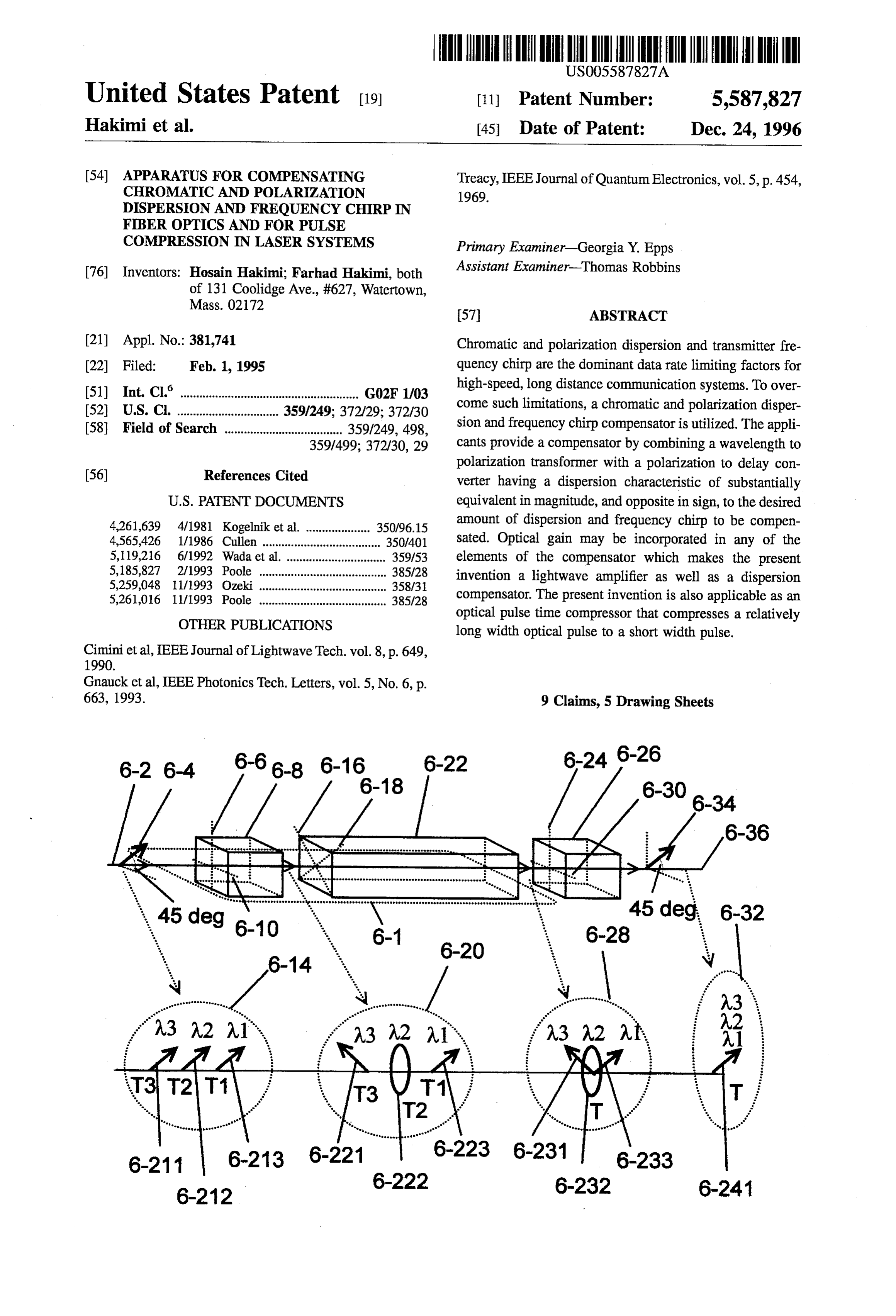
United States Patent (19) 11) Patent Number: 5,587,827 Hakimi et al. 45 Date of Patent: Dec. 24, 1996 54). APPARATUS FOR COMPENSATING Treacy, IEEE Journal of Quantum Electronics, vol. 5, p. 454, CHROMATIC AND POLARIZATION 1969.
DISPERSION AND FREQUENCY CHIRPIN
FIBER OPTICS AND FOR PULSE
COMPRESSION IN LASER SYSTEMS Primary Examiner-Georgia Y. Epps 76) Inventors: Hosain Hakimi, Farhad Hakimi, both Assistant Examiner-Thomas Robbins of 131 Coolidge Ave., #627, Watertown,
21 Appl. No.: 381,741 Chromatic and polarization dispersion and transmitter fre 22 Filed: Feb. 1, 1995 quency chirp are the dominant data rate limiting factors for (51) Int. Cl. .................... G02F1/03 high-speed, long distance communication systems. To over 52 U.S. Cl. ................. ... 359/249; 372/29; 372/30 come such limitations, a chromatic and polarization disper 58 Field of Search ..................................... 359/249, 498, sion and frequency chirp compensator is utilized. The appli 359/499; 372/30, 29 cants provide a compensator by combining a wavelength to polarization transformer with a polarization to delay con (56) References Cited verter having a dispersion characteristic of substantially
4,261,639 4/1981 Kogelnik et al. .................... 350/96.15 amount of dispersion and frequency chirp to be compen 4,565,426 1/1986 Cullen....... 350/401 sated. Optical gain may be incorporated in any of the 5,119,216 6/1992 Wada et al. ............................... 359/53 elements of the compensator which makes the present 5,185,827 2/1993 Poole ........................................ 385/28 invention a lightwave amplifier as well as a dispersion 5,259,048 11/1993 Ozeki ... ... 358/31 5,261,016 11/1993 Poole ........................................ 385/28 compensator. The present invention is also applicable as an optical pulse time compressor that compresses a relatively
OTHER PUBLICATIONS long width optical pulse to a short width pulse. Ciminietal, IEEE Journal of Lightwave Tech. vol. 8, p. 649,
Gnaucket al, IEEE Photonics Tech. Letters, vol. 5, No. 6, p.
663, 1993. 9 Claims, 5 Drawing Sheets
Page 2
Drawing sheet — no readable text.
Page 3
Drawing sheet — no readable text.
Page 4
Drawing sheet — no readable text.
Page 5
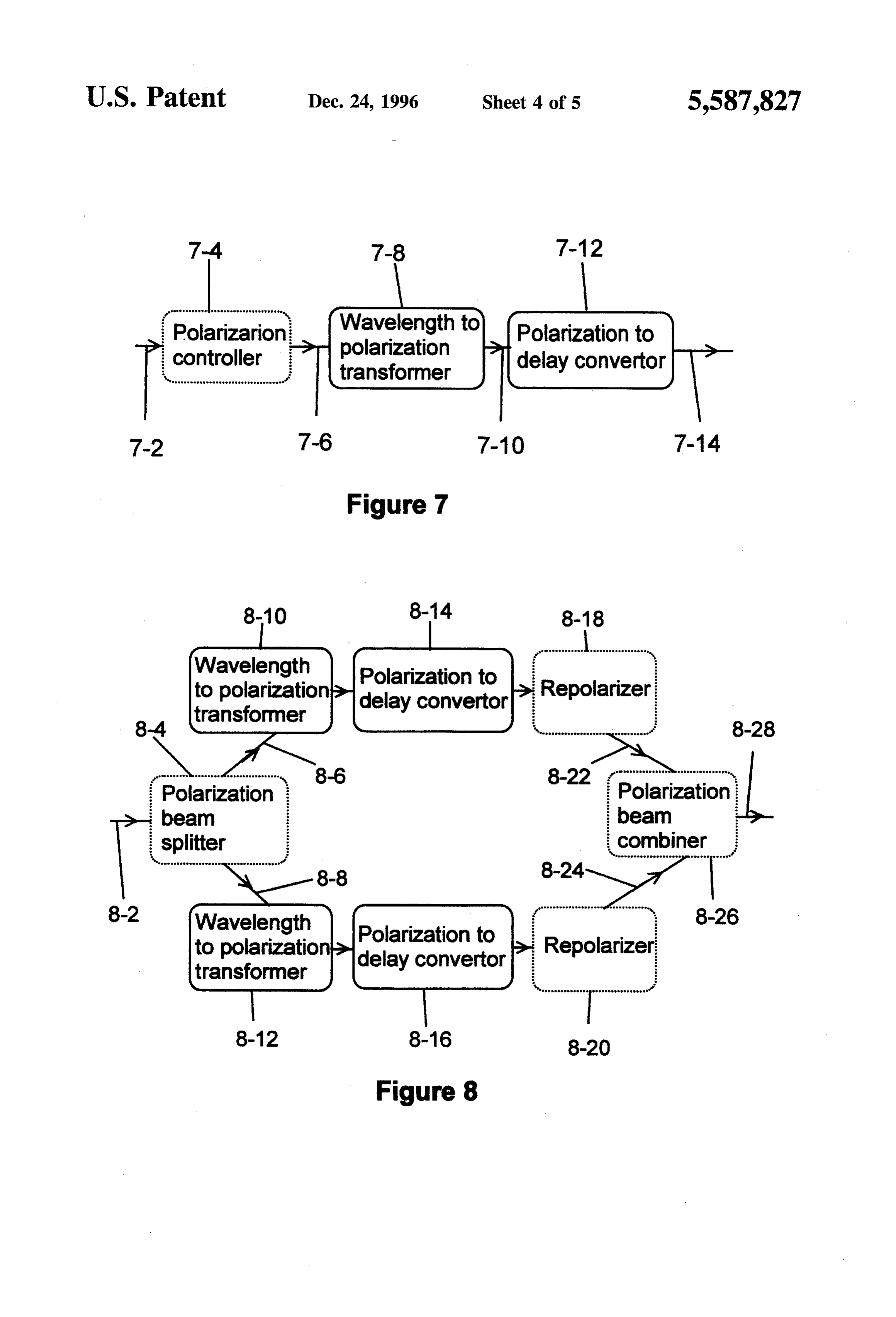
7-4 7-8 7-12 ise reserve posseverview ouvre.
7-2 7-6 7-10 7-14
Wavelength to polarization Repolarizer 8-4 transformer i 8-28 Nwaakrum. 8-6 8-22 gsd&disk messess Polarization Polarization beam beam splitter lcombiner
Wavelength - 8-26 to polarization transformer
Page 6
Drawing sheet — no readable text.
Page 7
APPARATUS FOR COMPENSATING appropriate lengths and having opposite group velocity CHROMATIC AND POLARIZATION dispersion characteristic so that the total dispersion in one DISPERSION AND FREQUENCY CHIRPIN fiber is substantially matched and canceled by the total FIBER OPTICS AND FOR PULSE dispersion in the connected fiber. While this is a possible COMPRESSION IN LASER SYSTEMS 5 solution, the length of compensating fibers are impractically BACKGROUND OF THE INVENTION long.
Use of Fabry-Perot etalon in transmissive and reflective
The present invention relates to compensation of chro structure for dispersion compensation is discussed in a paper matic and polarization dispersion and transmitter frequency by L. J. Cimini, I.J. Greenstein, and A. M. Saleh, "Optical chirp in fiber optical communication systems in order to 10 Equalization to Combat the Effects of Laser Chirp and Fiber increase the data rate. The invention is applicable to optical Dispersion", IEEE J. of Lightwave Tech. LT-8, Page 649 pulse time compression for producing short pulses from a (1990). The authors' technique requires continuous moni long chirped pulses. The invention is also relevant to stretch toring and tuning and appropriate means of feedback for ers and compressors for distortionless amplification of short dispersion compensation and optical equalization. optical pulses. 15
A. H. Gnauck, R. M. Jopson, and R. M. Derosier, "10-Gb
One of the major applications of single-mode fiber con /s 360-km transmission over dispersive fiber using midsys cerns telecommunication, particularly, for trunk networks, tem spectral inversion', IEEE Photonics Technology Letters where long-haul high-data-rate links predominate. Millions Vol. 5 No. 6 Page 663 (1993) utilize mid-point spectrum of kilometers of single-mode optical fibers are already inversion technique by means of the nonlinear optical effects installed throughout the world. Most of the single-mode 20 in fibers to compensate for pulse distortion. Gnaucketal and fibers installed have high chromatic dispersion which limits Cimini et al methods are complicated and do not lend itself the speed of intensity-modulated direct-detection optical to reliable practical commercial systems. fiber communication links. There are, currently, single-mode The present invention compensator has several advan fibers available with less chromatic dispersion suitable for tages over prior arts. Unlike others, the present compensator ultrahigh-speed long distance optical communication sys 25 corrects polarization as well as chromatic dispersion. The tems. However, the cost of removing the old fiber cables and discussed prior arts either are too complicated to implement installing new ones is prohibitive. Therefore, it is highly or have excessively high loss or impractically long lengths. economical to increase the usable bandwidth of existing The present invention is simple, low cost, compact, broad installed fibers without installing new ones.
30 band, and low loss which lends itself to commercial utili
Fiber loss and dispersion are two fundamental limiting zation. A second application of the present invention is factors in bandwidth of intensity-modulated direct-detection related to optical pulse compression. Optical pulse compres optical fiber communication system. With recent advent of sion for producing picosecond and subpicosecond laser rare earth optical amplifiers, dispersion of single-mode fiber pulses has become of great interest in recent years. A has become the dominant limitation for ultrahigh-speed long 35 traditional method to compress optical pulses is to employ a distance optical communication systems. There are two pair of diffraction gratings. E. B. Treacy. "Optical Pulse major contributions to dispersion, chromatic and polariza Compression with Diffraction Gratings", IEEE Journal of tion. Chromatic dispersion causes pulse broadening due to unequal speed of different wavelength components of light controllableElectronics
group delay of a grating pair to overcome the pulse in the fiber. Polarization mode dispersion arises in 40 inherent negative chirp of the picosecond pulses from a single-mode fiber when the combined effects of non-sym passively mode locked Nd-Glass laser. While grating pair metric internal stresses and noncircularity of the waveguide method is effective, it suffers from high loss that may be geometry created during manufacture cause the two polar unacceptable penalty for many practical applications. ization modes of the waveguide to propagate with different As a pulse compressor for laser systems, unlike other group velocities. Polarization mode dispersion like chro 45 methods, the present invention is low loss and simple and matic dispersion broadens the optical pulse in optical fibers. can compress positively chirped as well as negatively Diode lasers may produce a frequency chirped optical chirped optical pulses.
pulse upon pulsed excitation. Each wavelength (frequency) In some applications, such as shod optical pulse ampli components of a chirped optical pulse are emitted in differ ent time, hence, causing different delays for every wave 50 frequencya chipping.
fication, pulse is intentionally broadened by means of
The frequency chirped pulse is ampli length. Therefore, a chirped optical pulse resembles a dis fied and, subsequently, time compressed. The reason for persion broadened optical pulse where every wavelength component has experienced different delays. In long dis initial broadening of the pulse is to obviate the saturation tance optical communication systems, dispersion degrades effects power in the optical amplifier, due to high optical pulse density. The present invention is relevant in both system performance by either limiting the maximum data 55 initial pulse broadening and subsequent pulse compression rate or by requiring a shorter distance between repeaters. in optical amplifiers.
To upgrade existing networks based on standard single mode fiber, several all-optical dispersion compensation techniques have been proposed. Approaches described in SUMMARY OF THE INVENTION
mode converter with a dispersive waveguide having an It is accordingly a primary object of the present invention opposite dispersive characteristic to balance the unwanted to provide a method and means of compensation of chro chromatic dispersion. Disadvantage of these techniques is matic and polarization dispersion and laser frequency chirp excessive loss due to mode conversion and long length of in optical fibers in order to increase data rate in fiber optic dispersive waveguide for commercial systems. 65 communication systems.
Another method as described in U.S. Pat. No. 4,261,639, It is another object of the present invention to provide a involves the interconnection of two optical fibers having method and means of optical pulse compression.
Page 8
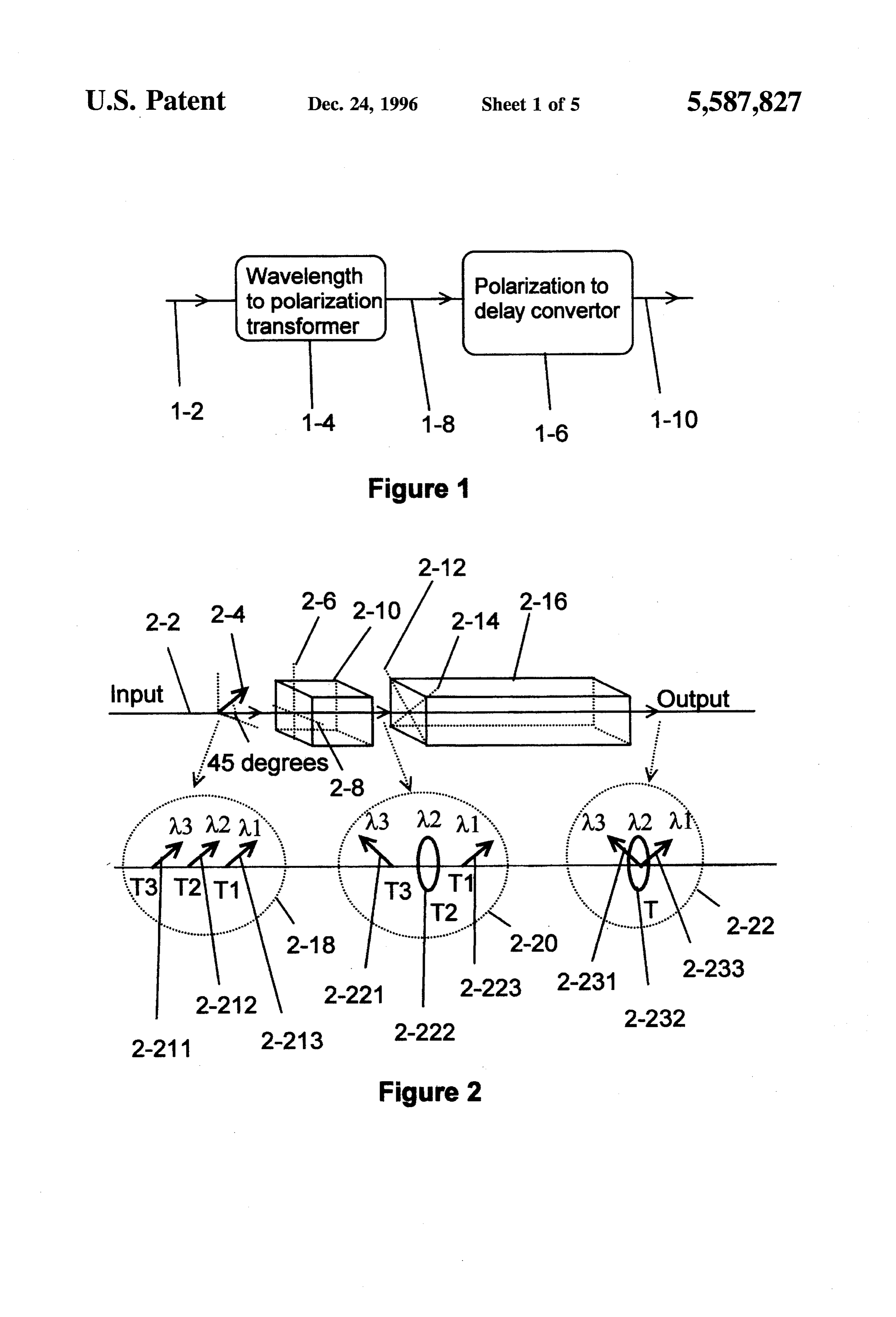
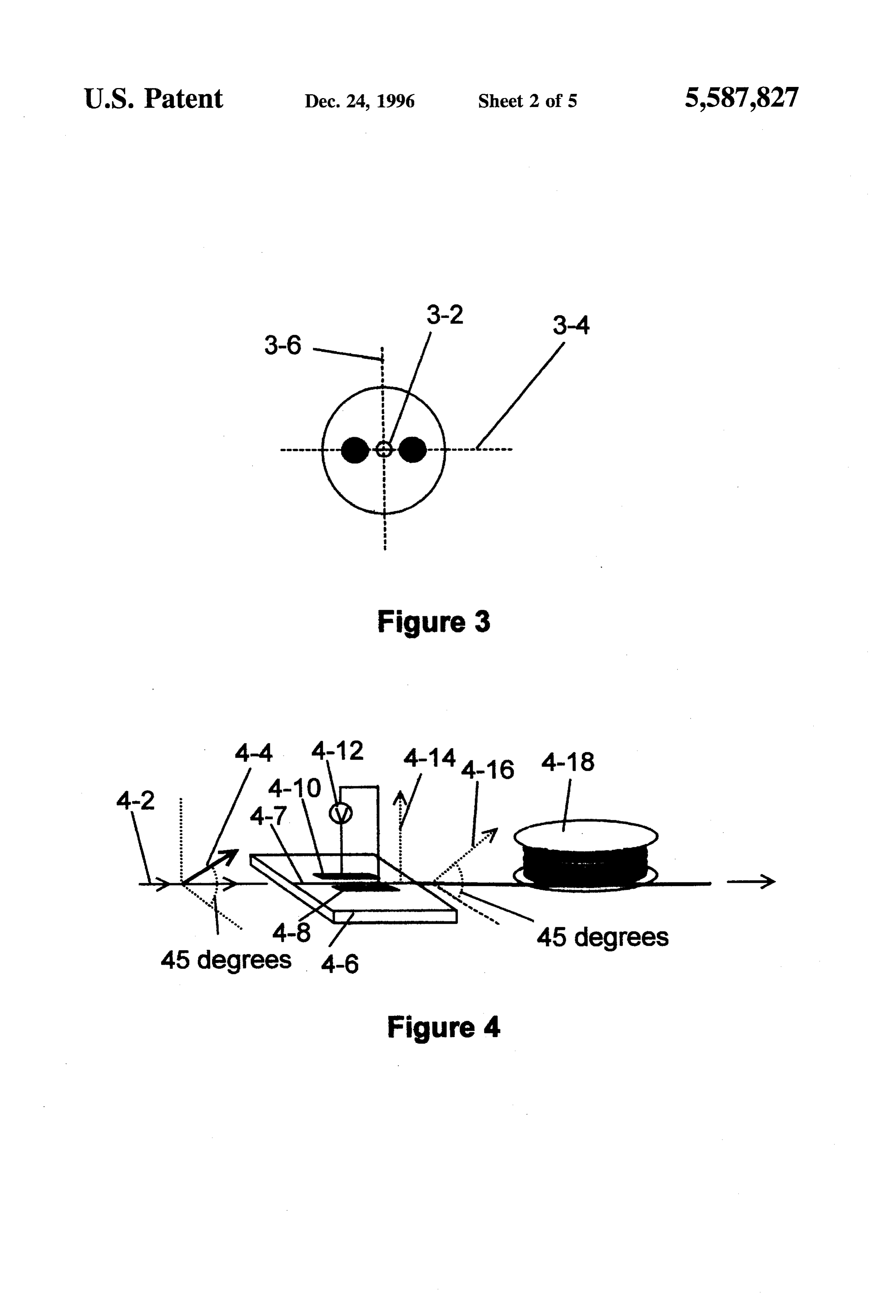
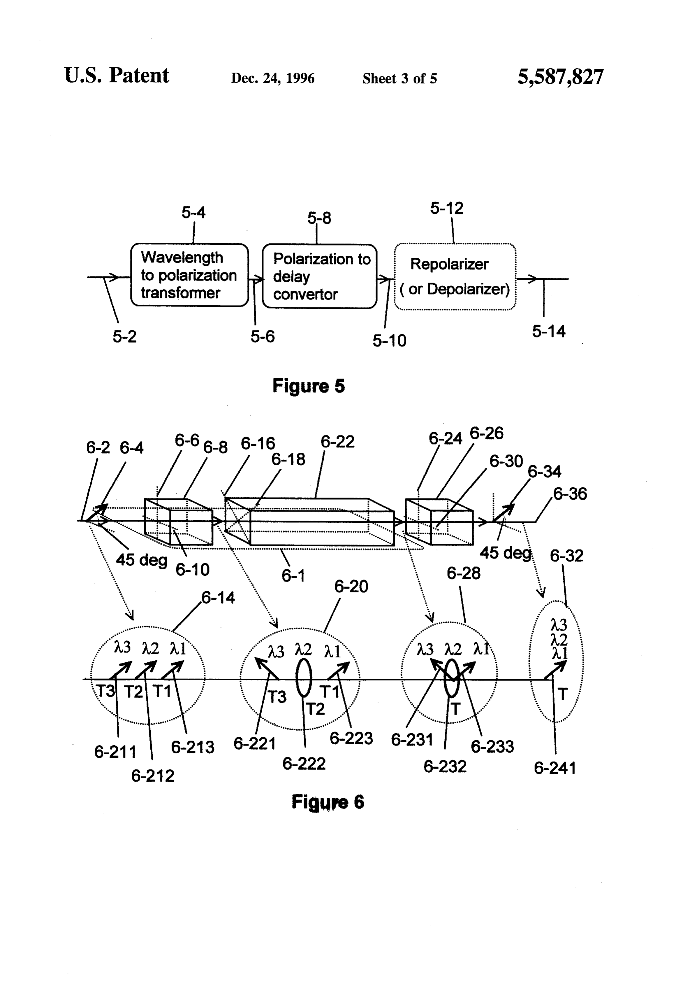
It is also object of the present invention to provide a FIG. 2 shows an embodiment of the present invention chromatic and polarization dispersion and laser chirp com with birefringent elements, pensator with optical gain for fiber optics applications. FIG. 3 depicts a cross section and principal axes of a Yet another object of the present invention to provide a birefringent fiber, light pulse compressor which has optical gain. FIG. 4 shows a birefringent integrated optics waveguide pigtailed
To increase information capacity of a fiber optic commu approximately to a birefringent fiber with their principal axes nication link, a chromatic and polarization dispersion and birefringence 45 degrees from each other and means of laser frequency chirp compensator is utilized. The applicants adjustment of the integrated optics waveguide provide a chromatic dispersion and frequency chirp com 0 in accordance with the principles of the present invention, pensator by combining a wavelength to polarization trans FIG. 5 schematically illustrates another block diagram former element with a polarization to delay converter ele embodiment of the present invention, ment having a dispersion characteristic of substantially FIG. 6 shows an embodiment of the dispersion and equivalent in magnitude, and opposite in sign, to the desired frequency chirp compensator with a repolarizer (or depo amount of dispersion and frequency chirp to be compen larizer) stage in accordance with the principles of the present sated. The wavelength to polarization transformer element 15 invention, alters each wavelength component of an input light pulse to FIGS. 7-9 schematically illustrate various block diagram different state of polarization. By performing the polariza embodiments of the present invention, tion transformation, it is possible to exploit the larger FIG. 10 shows an embodiment of the chromtic dispersion opposite dispersion in the polarization to delay converter 20 and frequency chirp compensator where optical gain is element to counteract the chromatic dispersion and trans incorporated in the present invention. mitter frequency chirp. It is noted that the compensation of dispersions and laser chirp may be done before, during, or after exposure to the undesirable effects. Optical gain may DETALED DESCRIPTION be incorporated in any of the elements of the compensator 25 Optical fibers present themselves as potentially high data which makes the present invention a light amplifier as well as a compensator. Any elements of the present invention rate as communication links. However, deleterious effects such chromatic and polarization dispersion and laser frequency may be of bulk optics or guided wave type. Furthermore, any chirp may diminish elements of the present invention may be of passive or active information capacity the of usefulness of this potential large the optical fiber links.
in nature. The present invention is also applicable as an 30 optical pulse time compressor that compresses a relatively Semiconductor lasers are used in pulsed mode in tele long width optical pulse to a short width pulse. communications to transmit data over fiber optic cables. Pulsed lasers may suffer from frequency chirp. Frequency
The light pulse leaving the polarization to delay converter chirp element of the compensator is partially depolarized. In one sourceoccurs when the frequency (or wavelength) of the embodiment a repolarizer (or depolarizer) is placed follow 35 tion. Invaries as a function of time during the pulse excita ing the polarization to delay converter element in order to components in words, other some frequencies (or wavelengths) the pulse are emitted earlier than the others have a polarized (or depolarized) compensated output. in the light pulse. Chromatic dispersion in fiber has the effect In other embodiment, a polarization controller is placed of delaying certain wavelengths (or frequencies) compo before the wavelength to polarization transformer in order to nents of an input beam with respect to the other components. convert an input lightwave to a linearly polarized light of 40 In effect, a light pulse suffering from chromatic dispersion is proper orientation to substantially eliminate any dispersion similar to frequency chirped pulse because each wavelength and frequency chirp distortions. component is delayed differently with respect to each other. Yet other embodiment of the present invention includes For this reason, the present invention treats the frequency the use of a depolarizer before the wavelength to polariza chirp and chromatic dispersion in the same way. These tion transformer element and a repolarizer after the polar 45 deleterious effects in communication systems limit the band ization to delay converter element in order to substantially width of the fiber links by broadening the optical pulses exclude the effects of depolarization in an input light pulse. thereby reducing the bit rate of data signals. This embodiment of the invention balances the undesirable In some applications, like short optical pulse amplifica polarization dispersion in addition to unwanted chromatic tion, a short pulse is intentionally broadened through fre dispersion and frequency chirp of an input lightwave. 50 quency chirping and then amplified in order to avoid satu
Still another embodiment of this invention includes a ration effects of the optical amplifier. The amplified polarization beam splitter and a polarization beam combiner frequency chirped optical pulse is subsequently compen on the ends of two compensators operating in parallel. This sated (compressed) to produce the short optical pulse. The embodiment of the present invention compensates polariza 55 present invention is applicable as a pulse stretcher as well as tion dispersion as well as chromatic dispersion and fre a pulse compressor.
quency chirp of an input pulse. In accordance with the principles of the present invention, Optical gain may be included in any stages of the com fiber chromatic and polarization dispersion and source fre pensators of the present invention. In addition, the nature of quency chirp may be substantially compensated. The present any elements of the present invention may be passive 60 invention transforms (conditions) each wavelength compo (birefringent fiber) or active (Ti:LiNbO3 waveguide with nent of a linearly polarized beam to different states of electrodes and voltage source). polarization. Different states of polarization experience dif ferent delay in such a fashion that slow components catch up with fast components, hence, causing the pulse to compress.
BRIEF DESCRIPTION OF THE DRAWINGS 65 FIG. 1 illustrates in block diagram form an embodiment FIG. 1 schematically illustrates a block diagram embodi of the compensator of the present invention. The compen ment of the present invention, sator consists of two stages 1-4 and 1-6. A linear polarized
Page 9
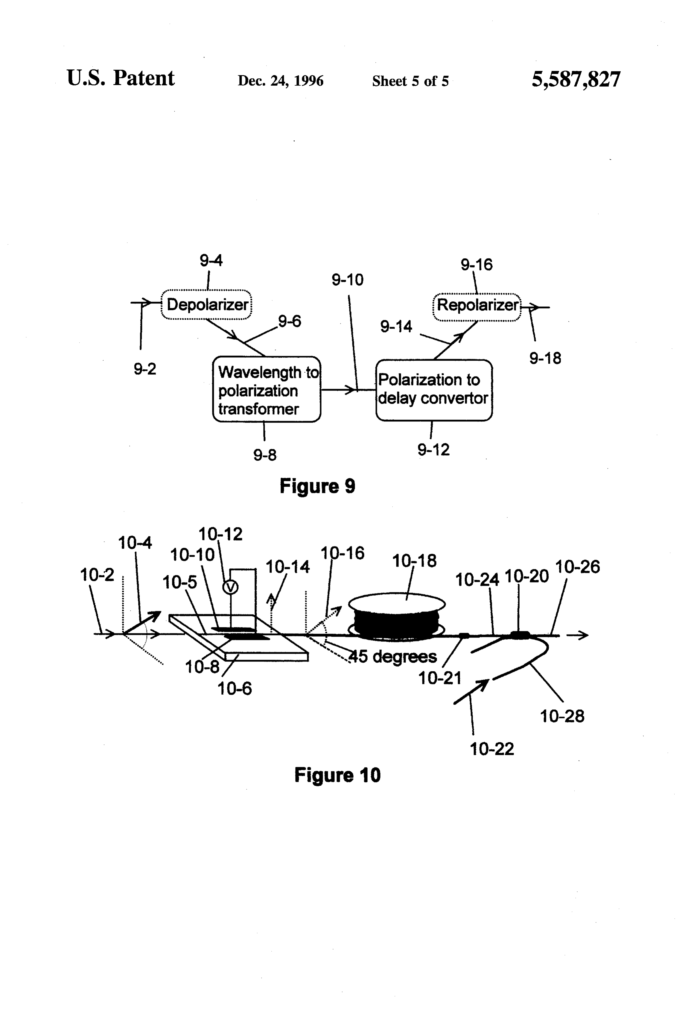
S 6 light 1-2 suffering from chromatic dispersion and frequency gent fiber 4-18. The planar waveguide 4-7 is formed on a die chirp is conditioned in the first stage 1-4 of the compensator of LiNbO3 4-6. The polarization axis 4-4 of a beam 4-2 in such a way that each wavelength component of the input makes an angle approximately 45 degrees from the principal beam is converted into different states of polarization. The axis 4-14 of the birefringent planar waveguide 4-7. The second stage of the compensator 1-6 has different time delay planar waveguide 4-7 is used as wavelength to polarization for each state of polarization. The time delay in the second transformer. Electrodes 4-8 and 4-10 and a voltage source stage of the compensator is selected (or adjusted) so that the 4-12 provide a means for adjustment of the polarization slow wavelength components in the lightwave overtake the mode delay of the waveguide 4-7. Abirefringent fiber 4-18 fast components of the beam, thereby compressing the input is used as the polarization to delay converter. The fiber 4-18 pulse. FIG. 2 illustrates an embodiment of the present 10 is pigtailed to the planar waveguide 4-7 as shown in the FIG. invention. A polarized input beam 2-2 suffering from fre 4. The principal axis 4-16 of birefringent fiber 4-18 is quency chirp and chromatic dispersion is illustrated in 2-18. approximately 45 degrees from the principal axis 4-14 of For simplicity and better illustration, with no loss of gen planar waveguide 4-7 in the neighborhood of the pigtail. erality, only three wavelength components of the input pulse In all discussed embodiments of the present invention, as are shown. W1 is the least delayed wavelength and 3 is the 15 described in the FIGS. 1, 2, and 4, the output pulse has been most delayed wavelength while A2 has a delay equal to compressed (compensated), however, partially depolarized. average of Al and A3. Some applications demand either totally polarized or totally Wavelength components 1, 2, and 23, shown in 2-18, depolarized output pulse. To address these applications, a are delayed differently in time due to chromatic dispersion repolarization or depolarization stage is added to the two in a fiber or frequency chirp of a laser source. The input 20 aforementioned stages of the compensator of the present beam 2-2 is linearly polarized with its polarization axis 2-4 invention. FIG. 5 shows in block diagram form of yet making an angle approximately 45 degrees from the prin another embodiment of the compensator of the present cipal axes 2-6 and 2-8 of a birefringent element 2-10. The invention where a repolarizer or depolarizer stage 5-12 is birefringent element 2-10 transforms each wavelength com placed after the polarization to time delay converter element. ponent (of the same polarization) of the input beam into 25 A polarized output beam is desirable when the outputs of different states of polarization. This is depicted in the bubble two compensaters are to be combined by means of a 2-20 where 1 is linearly polarized in the original polariza polarization beam combiner. The depolarizer stage may be tion state while A2 is circularly polarized and A3 is linearly useful in applications where polarization sensitive elements polarized orthogonal to 1. Although, the state of polariza are involved.
tion of each wavelength component has changed, the time 30 FIG. 6 illustrates an embodiment of the compensator of delay between them remains essentially unchanged as the present invention with a repolarizer (or depolarizer) shown in the bubble 2-20. This conditioned light enters a stage 6-26. The compensator 6-1 (as described in FIG.2) has birefringent element 2-16. The principal axes of the element the wavelength to polarization transformer element 6-8 and 2-16 are angled approximately 45 degrees from the principal polarization to delay converter element 6-22. The polariza axes of the birefringent element 2-10. The birefringent 35 tion to delay element 6-22 is followed by a birefringent element 2-16 causes each state of polarization (hence each element 6-26. The principal axes of the element 6-26 are wavelength component) to experience different delays in approximately parallel to the principal axes of the element such a way that slow wavelength components can catch up 6-8. Furthermore, the polarization mode delay of the ele with the fast components, thereby compressing the pulse. ments 6-26 is substantially equal to polarization mode delay This may be achieved, as shown in FIG. 2, by orienting the 40 element 6-8. In the case that the element 6-26 to be used as slow (higher index of refraction) axis of the birefringent repolarizer, the principal slow axis of the element 6-26 is element 2-16 along with the least delayed wavelength com parallel to the fast principal axis of the element 6-8. The ponent 1. The most delayed wavelength component A3 is output beam 6-36 would emerge as polarized radiation as oriented along the fast axis (lower index of refraction) of shown in the bubble 6-32 if the repolarization element is birefringent element 2-16 so that it can catch up with 1, 45 employed. In the case that the element 6-26 to be used as provided that the length of element 2-16 is selected properly. depolarizer, the slow principal axis of the element 6-26 is The intermediate delayed wavelength 2 is circularly polar approximately parallel to the slow principal axis of the ized and experiences an average of A1 and A2 delays. element 6-8.
Consequently, A2 and A3 are caught up with 1 upon going In the case that the input beam to be compensated is through the birefringent element 2-16, as depicted in the 50 polarized but not linearly polarized, a polarization controller bubble 2-22, and the input pulse is compressed. It is essen may be employed. FIG.7 shows another embodiment of the tial, for pulse compression, that the slow axis of the bire present invention. A polarization controller 7-4, as shown in fringent element 2-16 to be oriented along the polarization FIG.7, changes a polarized (elliptically) input beam 7-2 to axis of the least delayed wavelength component. It is equally a linearly polarized beam 7-6 of proper orientation for the important that the fast axis of the birefringent axis 2-16 be 55 element 7-8 to achieve the pulse compensation. oriented along the polarization axis of the most delayed The compensators described so far allow one to compress wavelength components of the light pulse. (compensate) a polarized beam. However, the compensator Birefringent fibers and planar waveguides constitute of FIG. 8, still another embodiment of the present invention, excellent media to realize the compensator of the present provides the compensation regardless of the polarization invention. An example of birefringent waveguide is planar state of an input beam (elliptical or partially polarized). An optical waveguides made from a die of LiNbO3 (Lithium input beam of light 8-2 is split by apolarization beam splitter Niobate) having diffused Ti (titanium) waveguide 8-4 into two orthogonally polarized beams 8-6 and 8-8. The (Ti:NbO3) which exhibit linear birefringent. FIG. 3 shows a polarized beam 8-6 is compensated into polarized beam 8-22 cross section of a birefringent fiber with the core 3-2 and through compensator repolarizer stages 8-10, 8-14, and principal axes 3-4 and 3-6. 65 8-18. Similarly, the polarized beam 8-8 is compensated into FIG. 4 illustrates an embodiment of the present invention polarized beam 8-24 through stages 8-12, 8-16, and 8-20. utilizing a Ti:LiNbO3 planar waveguide 4-7 and a birefrin The two orthogonally polarized and compensated beams
Page 10
8-22 and 8-24 are combined into a single beam 8-28 by an output of the first transforming means for compen means of polarization beam combiner 8-26. The output sating chromatic dispersion and frequency chirp of the beam 8-28 is polarized and compensated. This embodiment lightwave by inducing an amount of chromatic disper (FIG. 8) of the present invention has the advantage (over sion substantially equal in magnitude, and opposite in FIGS. 1, 2, 4, 5, 6, and 7) that it can compensate polarization sign, to the predetermined amount of chromatic disper dispersion in addition to chromatic and frequency chirp. sion and polarization dispersion and frequency chirp. FIG. 9 illustrates yet another embodiment of the present 2. The apparatus as defined in claim 1 further comprising: invention relevant for polarization and chromatic dispersion a means for amplifying the lightwave signal. and frequency chirp compensation. A beam 9-2 is depolar 3. The apparatus as defined in claim 1 further comprising: ized into beam 9-6 by a depolarizer element 9-4. The 10 depolarized beam 9-6 consists of two orthogonally polarized a means for controlling the polarization of the lightwave pulses with no correlation between them. The two compo signal in order to produce a specific state of polariza nents in 9-6 are compensated into a beam 9-14 by means of tion and wherein said means for controlling the polar elements 9-8 and 9-12, as shown in FIG. 9. The Beam 9-14 ization is coupled to an input of the first means for consists of two compensated orthogonally polarized light 15 transforming each wavelength component of the light pulses with no correlation between them. A repolarizer stage wave to different polarization state. 9-16 of proper delay can repolarize the depolarized beam 4. The apparatus as defined in claim 1 further comprising: 9-14 into a polarized beam 9-18. a means for repolarizing the lightwave signal and wherein Any elements of the present invention may be of passive said means for repolarization is connected to an output or active type. Furthermore, optical gain may be incorpo 20 of the second means to convert each polarization state rated into any stages of the compensator or repolarization to a different respective time delay. (depolarization) stage of the present invention. FIG. 10 5. The apparatus as defined in claim 1 further comprising: shows an exemplary embodiment of the present invention a means for depolarizing the lightwave signal and wherein where optical gain is incorporated in the polarization to 25 said means for depolarization is connected to an input delay stage of the compensator. A linearly polarized beam of the first means for transforming each wavelength 10-2 with polarization axis 10-4 is coupled into a birefrin component of the lightwave to different polarization gent integrated waveguide 10-5 which is formed on a State.
substrate 10-6. The principal axis 10-14 of waveguide 10-5 6. Apparatus for compensating a predetermined amount of is approximately 45 degrees from the polarization axis 10-4. 30 chromatic dispersion and polarization dispersion and fre The electrodes 10-8 and 10-10 and the voltage source 10-12 quency chirp in a lightwave signal comprising: provide a means for adjustment of the polarization mode first means to depolarize the lightwave signal; and delay of the waveguide 10-5. The birefringent waveguide second means for transforming each wavelength compo 10-5 is the wavelength to polarization transformer element. ments of the lightwave to different respective polariza A birefringent fiber 10-18 is used as polarization to delay 35 tion states and wherein said second means for trans converter element. The fiber 10-18 is pigtailed to the forming is connected to an output of the first waveguide 10-5. The principal axis 10-16 of the birefringent depolarizer means; and fiber 10-18 is approximately 45 degrees from the principal axis 10-14 of the waveguide 10-5 in the neighborhood of the third means to convert each polarization state to a differ pigtail. The birefringent fiber 10-18 may include impurities ent respective time delay for compensating chromatic where upon excitation provide optical gain for the compen dispersion and polarization dispersion and frequency sated pulse. Examples of impurities are ions such as Erbium chirp of the lightwave by inducing an amount of or Praseodymium or Neodymium. These ions produce opti dispersion and frequency chirp substantially equal in cal gain in the fiber 10-18 when they are optically excited. magnitude, and opposite in sign, to the predetermined A wavelength sensitive coupler 10-20 is connected to the 45 amount of dispersion and frequency chirp and wherein output end of the birefringent fiber via a fiber splice 10-21. said third means to convertis connected to an output of The coupler 10-20 is selected so that pump excitation 10-22 the second means for transforming; and is coupled into the birefringent fiber 10-18 from coupler port fourth means to repolarize the lightwave to a polarized 10-28 to coupler port 10-24 while the output compensated light and wherein said fourth means to repolarize is pulse is coupled from coupler port 10-24 into coupler port 50 connected to an output of the third means to convert 10-26. The output light pulse, exiting the port 10-26, is each polarization state to a different respective time compensated and has experienced optical gain. Therefore, delay.
the compensator with optical gain constitutes a novel appa 7. The apparatus as defined in claim 6 further comprising: ratus that addresses the two foremost limiting factors in a means for amplifying the lightwave signal. telecommunications, namely, fiber loss and dispersion dis 55 8. Apparatus for compensating a predetermined amount of tortion. chromatic dispersion and polarization dispersion and fre What is claimed is: quency chirp in a lightwave signal comprising: 1. Apparatus for compensating a predetermined amount of a means to split the lightwave signal into two orthogonal chromatic dispersion and polarization dispersion and fre polarization components; and couple each said polar quency chirp in a lightwave signal, the apparatus compris 60 ization components into inputs of two compensators of 1ng: the claim 4; and a means to combine two orthogonal first means for transforming each wavelength component polarization components connected to the outputs of of the lightwave to different respective polarization two said compensators.
states; and 9. The apparatus as defined in claim 8 further comprising: second means to convert each different respective polar 65 a means for amplifying the lightwave signal. ization state to a different respective time delay and wherein said second means to convert is connected to ck k is k k
Provenance
- Collection
- Cited prior art
- Original PDF
- patentimages.storage.googleapis.com →
- Filed
- 1995-02-01
- Pages
- 10
- Method
- pdftotext (the PDF's own text layer) + pdftoppm 300dpi page scans
- Source
- Google Patents bibliographic record
- Granted
- 1996-12-24
- Inventors
- Hosain Hakimi; Farhad Hakimi
- Transcribed from
- patentimages.storage.googleapis.com →