patent · US4461278
Apparatus for collecting and transmitting solar energy
24 July 1984
Page 1 — bibliographic record
550 - 36.1 Six
United States Patent (19) 11 Patent Number: 4,461,278 Mori (45) Date of Patent: Jul. 24, 1984 (54). APPARATUS FOR COLLECTING AND 3,885,879 5/1975 Louder et al. ...................... 356/49 TRANSMITTING SOLAR ENERGY 4,257,401 3/1981 Daniels .............
76 Inventor: Kei Mori, 3-16-3-501, Kaminoge,
Setagaya-ku, Tokyo, Japan FOREIGN PATENT DOCUMENTS (21) Appl. No.: 361,892 14031 2/1979 Japan ................................... 126/440 (22 Filed: Mar. 25, 1982 Primary Examiner-Larry Jones Assistant Examiner-Helen A. Odar 30 Foreign Application Priority Data Attorney, Agent, or Firm-Burgess, Ryan & Wayne Apr. 2, 1981 JP Japan .................................. 56-49797
51 Int. Cli................................................ G02B 5/14 An apparatus for collecting and transmitting solar en 52 U.S. C. .................................... 126/440; 126/417; ergy, which has lenses for collecting beams of sunlight 350/96.10; 350/96.15; 350/96.18 and light guide cables or optical fiber cables for trans 58 Field of Search ............................... 126/440, 417; mitting the collected beams. Light-receiving end faces 350/96.18, 96.15, 96.10, 258, 259 of the light guides or the optical fibers are aligned with (56) References Cited focal positions of light components of desired colors, respectively.
3,185,021 5/1965 Thompson .......................... 356/332 2 Claims, 7 Drawing Figures
yATAT, AA
NKN NN NNNNNN
Page 2
Drawing sheet — no readable text.
Page 3
Drawing sheet — no readable text.
Page 4
Drawing sheet — no readable text.
Page 5
component is selected to be correctly focused on a
APPARATUS FOR COLLECTING AND light-receiving end face of the light guide.
TRANSMITTING SOLAR ENERGY Therefore, if all the light components of sunlight focused with the lens system and directed to the light
BACKGROUND OF THE INVENTION 5 guide are transmitted, a beam of sunlight which con The present invention relates to an apparatus for tains desired light components cannot be obtained. collecting and transmitting solar energy and, more par SUMMARY OF THE INVENTION ticularly, to an apparatus for collecting with a lens sys tem light beams including light components for a prede 10 It is an object of the present invention to provide an termined purpose and transmitting these light beams apparatus for collecting a beam of sunlight which in through a light guide to a desired place so as to utilize cludes desired light components in a relatively great the solar energy for the predetermined purpose. amount and for transmitting the beam of sunlight to a Recently, effective utilization of solar energy has desired place.
received great attention and extensive studies and fur It is another object of the present invention to pro ther developments have been made in various fields. 15 vide an apparatus for collecting and transmitting solar The mainstream of these developments is represented energy wherein desired light components of various by conversion of solar energy to another form of energy colors can be selectively transmitted in greater such as thermal energy, electrical energy or the like and amounts.
utilization of the energy in the converted form. How According to the present invention, a lens system is ever, it is also proposed that solar energy be directly 20 used to focus the beam of sunlight. In order to transmit utilized for a certain purpose. For example, the beam of the focused beam, an optical fiber cable is used and one sunlight may be focused with a lens system and led to a end thereof is positioned at a focal position of the lens. light guide, so that the light guide transmits the light In order to select desired light components, one end of beam to a desired place for illumination. the optical fiber cable is positioned at the focal position When sunlight is used for a special purpose, light 25 of the lens which corresponds to the selected light com components necessary for this purpose are preferably ponent.
selectively collected and transmitted. For example, In order to selectively transmit light components of when solar energy is to be utilized for illuminating natu various colors with a single apparatus, a structure is ral colors of clothes, white light which contains all 30 adopted wherein one end of the optical fiber cable can components is preferably used.
Further, solar energy may be utilized for growing be moved along an optical axis of light focused by the lens, and at the desired position can be fixed.
plants at the bottom of the sea. As a matter of fact, only Further, when light components of a plurality of bluish greenlight components reach the deep sea (100m selected colors are to be transmitted simultaneouly, a deep or more), and plants which grow with bluish green light components grow in the deep sea. On the other 35 cable which comprises a plurality of optical fibers is hand, since red light components are transmitted to the aused. Each end face of the optical fibers is positioned at corresponding focal position of the light component shallow sea (less than 100 m. deep), the plants which of the corresponding selected color. grow with red light components grow in the shallow sea. Therefore, if light which mainly includes more red invention Other objects, features, and advantages of the present light components is transmitted to the deep sea, shallow will be apparent from the following descrip sea plants can be grown in the deep sea. On the other drawings. tion when taken in conjunction with the accompanying hand, if light which mainly contains bluish green light components is transmitted to the bottom of the shallow BRIEF DESCRIPTION OF THE DRAWINGS sea, deep sea plants can be grown there.
Further, artificial culture of spirula and chlorella with 45 collecting1 isand
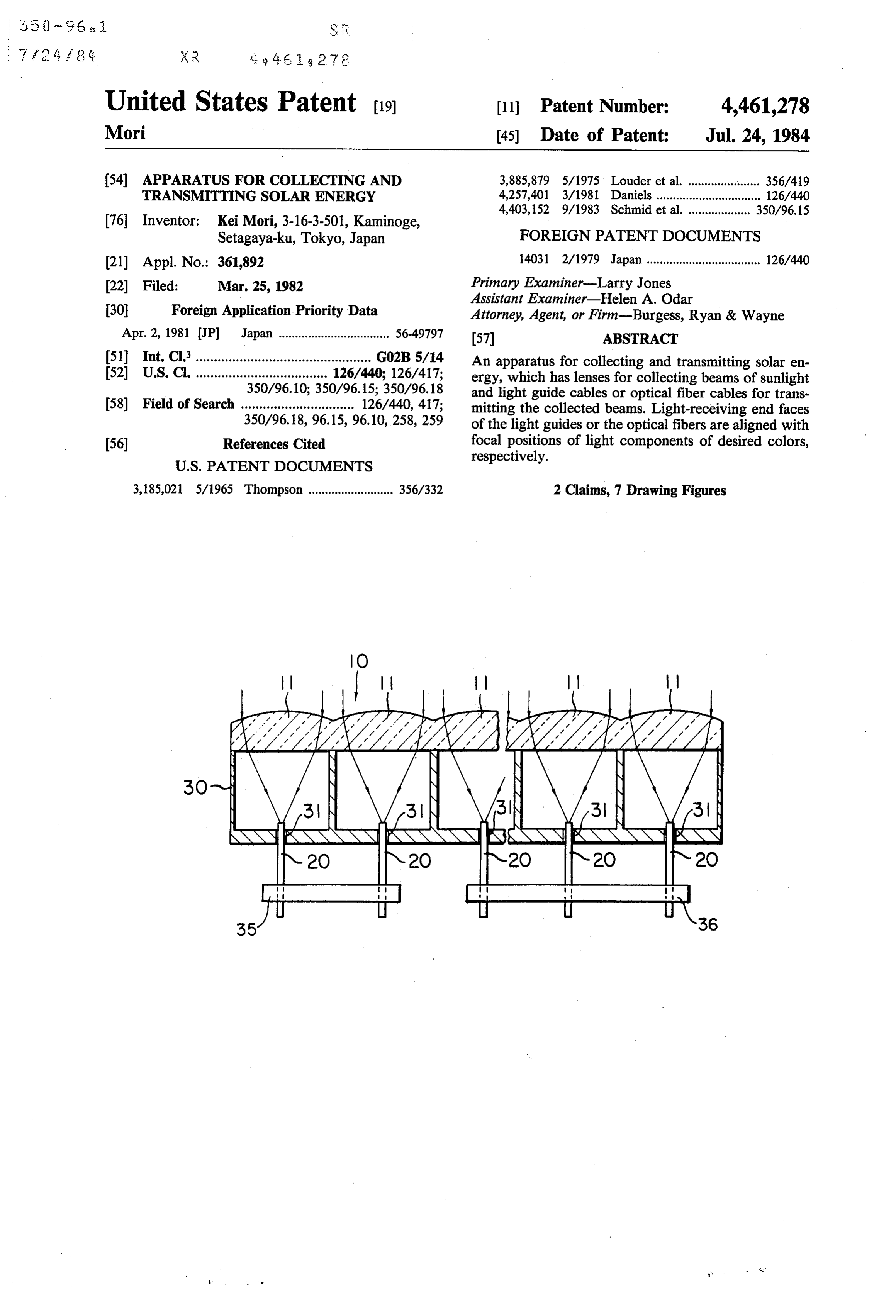
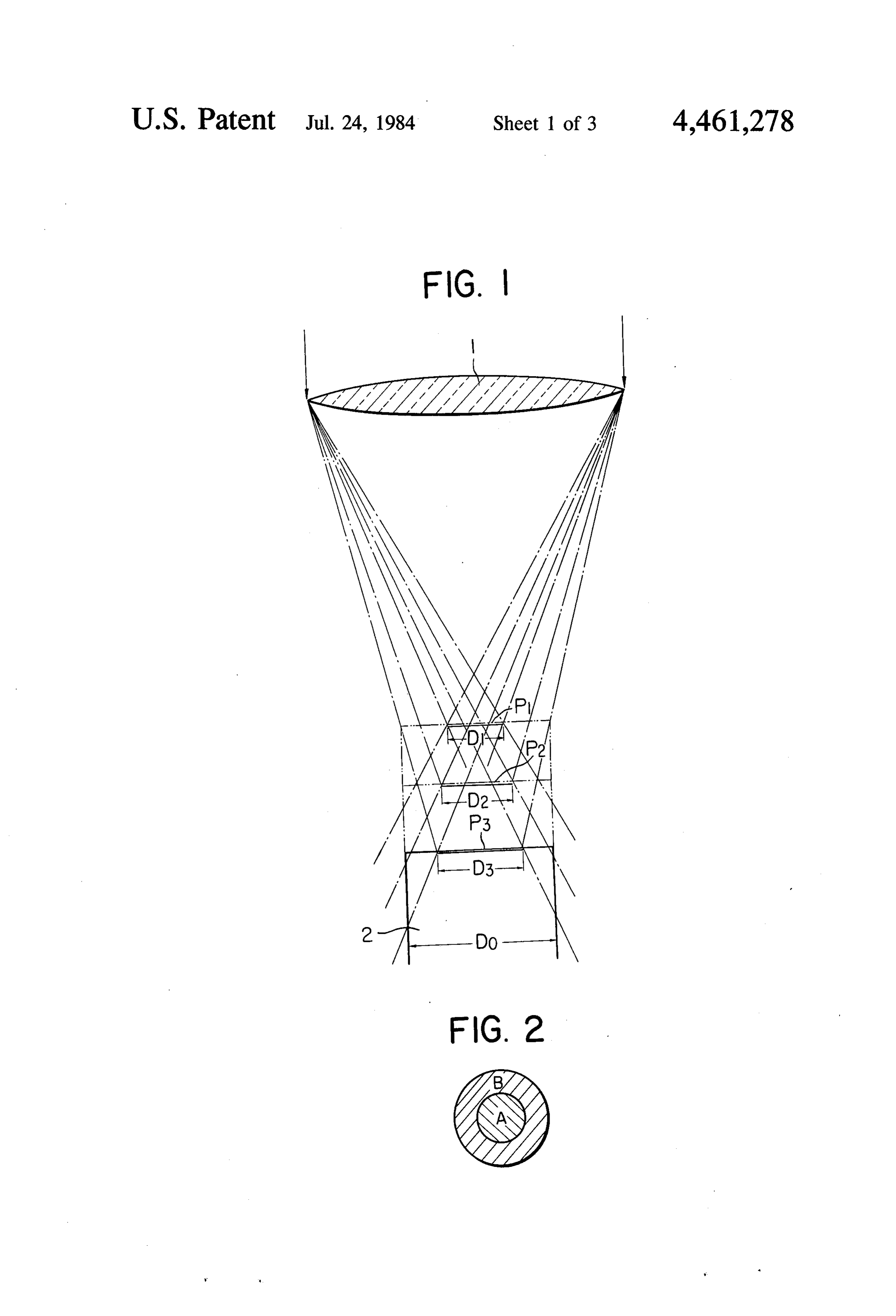
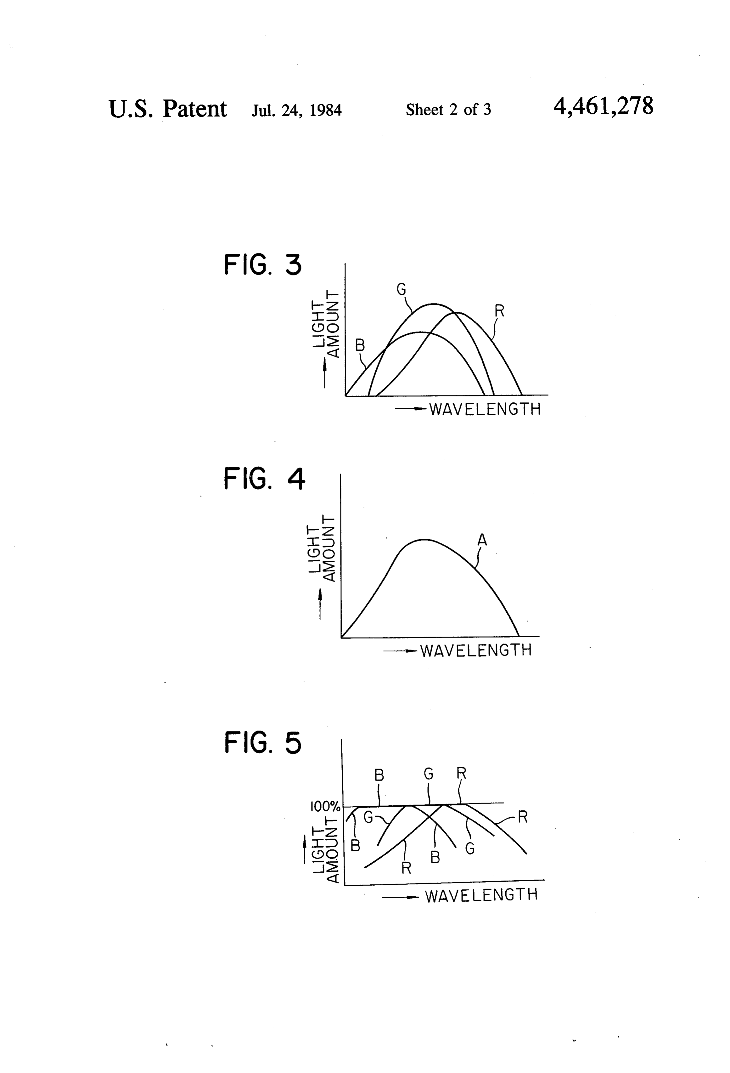
FIG. a transverse view of an optical system for transmitting solar energy according to solar energy may be performed.
Solar energy may also be utilized for raising animals, one embodiment of the present invention; improving a health condition, performing therapies, and FIG. 2 shows an image of the sun focused with a lens as a fishing light source (green) for catching fish. system;
In these cases, all light components of solar energy 50 FIGS. 3 to 5 are graphs showing spectral distribu are required for some purposes or specific light compo tions of solar light with relative intensity plotted as a nents thereof must be selected for others. Recently, function of wavelength;
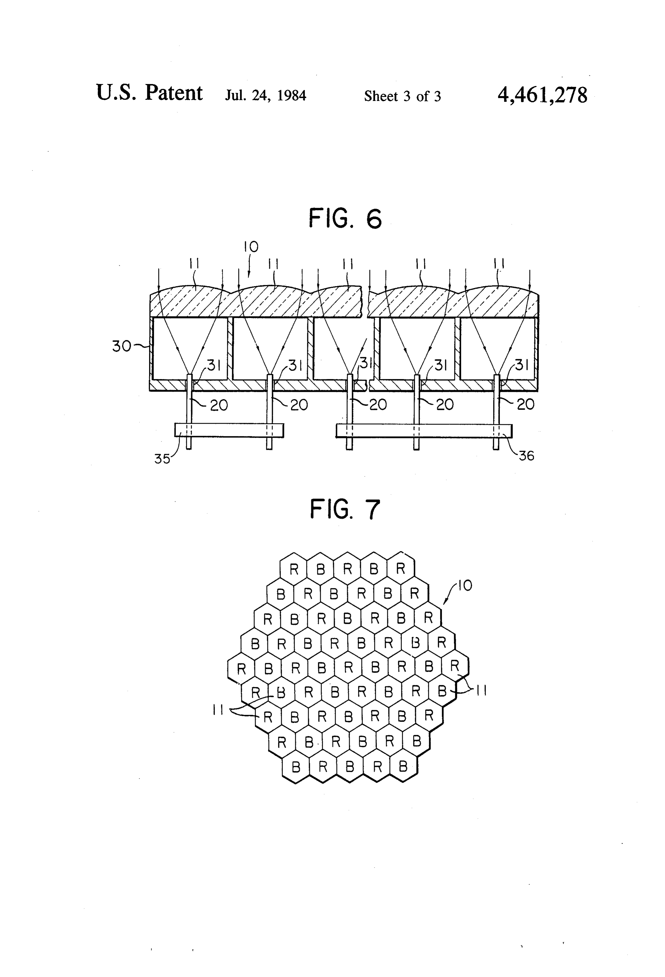
light components of solar energy have often been uti FIG. 6 is a schematic sectional view of the main part lized selectively. However, it is doubtful that desired of an apparatus for collecting and transmitting solar light components are utilized effectively. 55 energy according to another embodiment of the present For example, when solar energy is focused with a invention; and
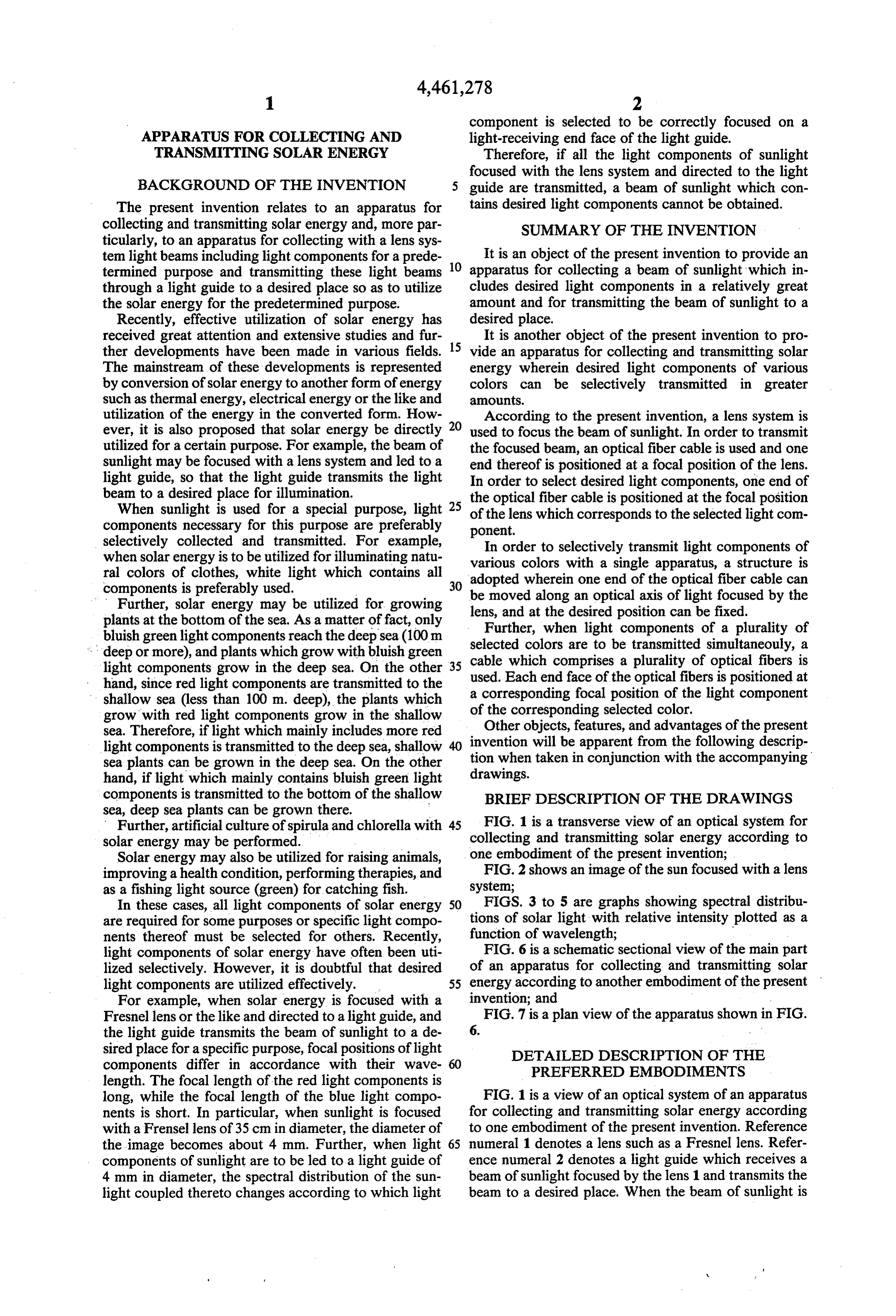
Fresnel lens or the like and directed to a light guide, and FIG. 7 is a plan view of the apparatus shown in FIG. the light guide transmits the beam of sunlight to a de 6. . sired place for a specific purpose, focal positions of light DETAILED DESCRIPTION OF THE components differ in accordance with their wave PREFERRED EMBODEMENTS length. The focal length of the red light components is long, while the focal length of the blue light compo FIG. 1 is a view of an optical system of an apparatus nents is short. In particular, when sunlight is focused for collecting and transmitting solar energy according with a Frensel lens of 35 cm in diameter, the diameter of to one embodiment of the present invention. Reference the image becomes about 4 mm. Further, when light 65 numeral 1 denotes a lens such as a Fresnel lens. Refer components of sunlight are to be led to a light guide of ence numeral 2 denotes a light guide which receives a 4 mm in diameter, the spectral distribution of the sun beam of sunlight focused by the lens 1 and transmits the light coupled thereto changes according to which light beam to a desired place. When the beam of sunlight is
Page 6
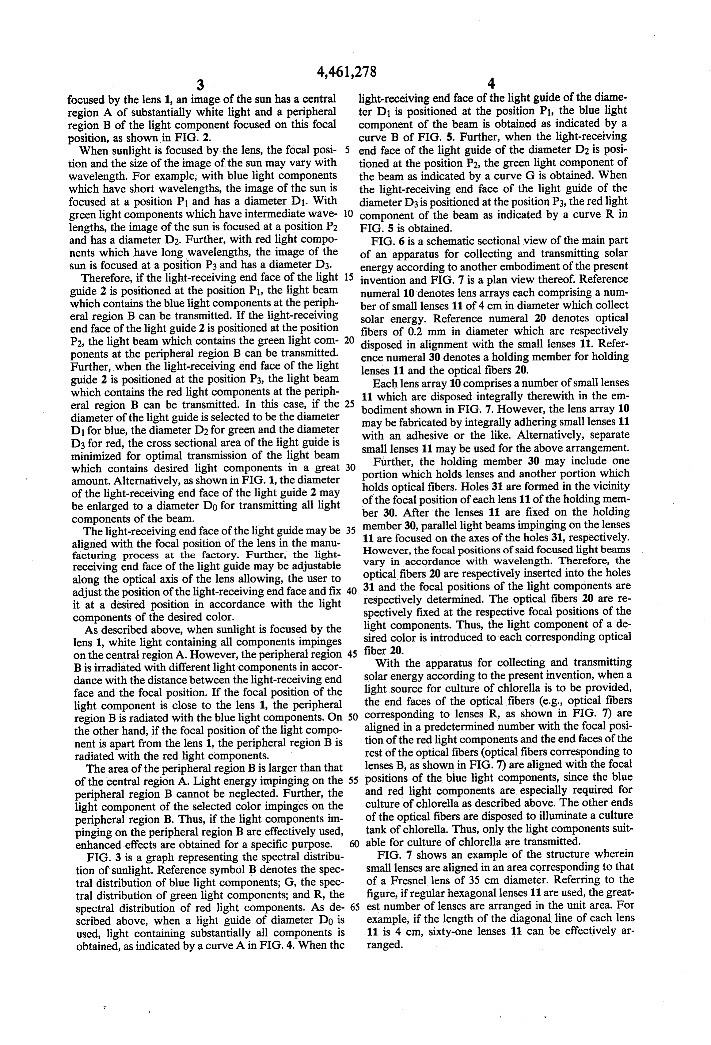
focused by the lens 1, an image of the sun has a central light-receiving end face of the light guide of the diame region A of substantially white light and a peripheral ter D1 is positioned at the position P1, the blue light region B of the light component focused on this focal component of the beam is obtained as indicated by a position, as shown in FIG. 2. curve B of FIG. 5. Further, when the light-receiving When sunlight is focused by the lens, the focal posi end face of the light guide of the diameter D2 is posi tion and the size of the image of the sun may vary with tioned at the position P2, the green light component of wavelength. For example, with blue light components the beam as indicated by a curve G is obtained. When which have short wavelengths, the image of the sun is the light-receiving end face of the light guide of the focused at a position P1 and has a diameter D1. With diameter D3 is positioned at the position P3, the red light green light components which have intermediate wave O component of the beam as indicated by a curve R in lengths, the image of the sun is focused at a position P2 FIG. 5 is obtained.
and has a diameter D2. Further, with red light compo FIG. 6 is a schematic sectional view of the main part nents which have long wavelengths, the image of the of an apparatus for collecting and transmitting solar sun is focused at a position P3 and has a diameter D3. energy according to another embodiment of the present Therefore, if the light-receiving end face of the light 15 invention and FIG. 7 is a plan view thereof. Reference guide 2 is positioned at the position P1, the light beam numeral 10 denotes lens arrays each comprising a num which contains the blue light components at the periph ber of small lenses 11 of 4 cm in diameter which collect eral region B can be transmitted. If the light-receiving solar energy. Reference numeral 20 denotes optical end face of the light guide 2 is positioned at the position fibers of 0.2 mm in diameter which are respectively P2, the light beam which contains the green light com 20 disposed in alignment with the small lenses 11. Refer ponents at the peripheral region B can be transmitted. ence numeral 30 denotes a holding member for holding Further, when the light-receiving end face of the light guide 2 is positioned at the position P3, the light beam lenses 11 and the optical fibers 20. which contains the red light components at the periph 11 whichlensarearray10
Each comprises a number of small lenses disposed integrally therewith in the em eral region B can be transmitted. In this case, if the bodiment shown in FIG. 7. However, the lens array 10
diameter of the light guide is selected to be the diameter may be fabricated by integrally adhering small lenses 11 D1 for blue, the diameter D2 for green and the diameter with an adhesive or the like. Alternatively, separate D3 for red, the cross sectional area of the light guide is minimized for optimal transmission of the light beam small lenses 11 may be used for the above arrangement. Further, the holding member 30 may include one which contains desired light components in a great 30 portion which holds lenses and another portion which amount. Alternatively, as shown in FIG. 1, the diameter holds optical fibers. Holes 31 are formed in the vicinity of the light-receiving end face of the light guide 2 may of the focal position of each lens 11 of the holding mem be enlarged to a diameter Do for transmitting all light ber 30. After the lenses 11 are fixed on the holding components of the beam.
The light-receiving end face of the light guide may be 35 member 30, parallel light beams impinging on the lenses aligned with the focal position of the lens in the manu 11 are focused on the axes of the holes 31, respectively. However, the focal positions of said focused light beams facturing process at the factory. Further, the light receiving end face of the light guide may be adjustable vary in accordance with wavelength. Therefore, the along the optical axis of the lens allowing, the user to 31 and fibers optical 20 are respectively inserted into the holes the focal positions of the light components are adjust the position of the light-receiving end face and fix respectively determined. The optical fibers 20 are re it at a desired position in accordance with the light spectively fixed at the respective focal positions of the components of the desired color. light components. Thus, the light component of a de As described above, when sunlight is focused by the lens 1, white light containing all components impinges sired color is introduced to each corresponding optical on the central region A. However, the peripheral region 45 fiber 20.
With the apparatus for collecting and transmitting
B is irradiated with different light components in accor solar dance with the distance between the light-receiving end light energy according to the present invention, when a source for culture of chlorella is to be provided, face and the focal position. If the focal position of the the end faces of the optical fibers (e.g., optical fibers light component is close to the lens 1, the peripheral region B is radiated with the blue light components. On 50 corresponding to lenses R, as shown in FIG. 7) are the other hand, if the focal position of the light compo aligned in a predetermined number with the focal posi nent is apart from the lens 1, the peripheral region B is tion of the red light components and the end faces of the radiated with the red light components. rest of the optical fibers (optical fibers corresponding to The area of the peripheral region B is larger than that lenses B, as shown in FIG. 7) are aligned with the focal of the central region A. Light energy impinging on the 55 positions of the blue light components, since the blue peripheral region B cannot be neglected. Further, the and red light components are especially required for light component of the selected color impinges on the culture of chlorella as described above. The other ends peripheral region B. Thus, if the light components im of the optical fibers are disposed to illuminate a culture pinging on the peripheral region B are effectively used, tank of chlorella. Thus, only the light components suit enhanced effects are obtained for a specific purpose. able for culture of chlorella are transmitted. FIG. 3 is a graph representing the spectral distribu FIG. 7 shows an example of the structure wherein tion of sunlight. Reference symbol B denotes the spec small lenses are aligned in an area corresponding to that tral distribution of blue light components; G, the spec of a Fresnel lens of 35 cm diameter. Referring to the tral distribution of green light components; and R, the figure, if regular hexagonal lenses 11 are used, the great spectral distribution of red light components. As de 65 est number of lenses are arranged in the unit area. For scribed above, when a light guide of diameter Do is example, if the length of the diagonal line of each lens used, light containing substantially all components is 11 is 4 cm, sixty-one lenses 11 can be effectively ar obtained, as indicated by a curve A in FIG. 4. When the ranged.
Page 7
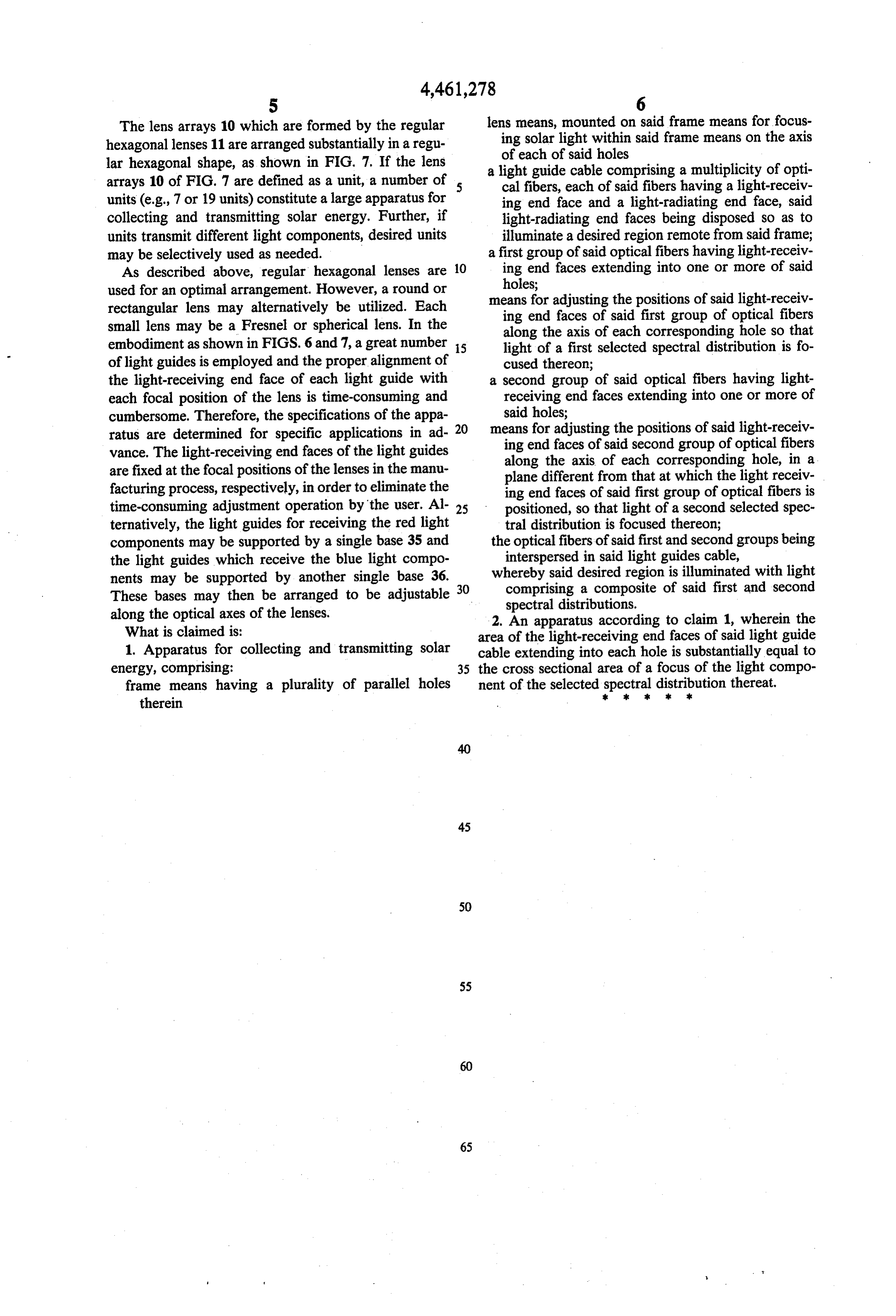
The lens arrays 10 which are formed by the regular lens means, mounted on said frame means for focus hexagonal lenses 11 are arranged substantially in a regu ing solar light within said frame means on the axis of each of said holes lar hexagonal shape, as shown in FIG. 7. If the lens a light guide cable comprising a multiplicity of opti arrays 10 of FIG. 7 are defined as a unit, a number of 5 cal fibers, each of said fibers having a light-receiv units (e.g., 7 or 19 units) constitute a large apparatus for ing end face and a light-radiating end face, said collecting and transmitting solar energy. Further, if light-radiating end faces being disposed so as to units transmit different light components, desired units illuminate a desired region remote from said frame; may be selectively used as needed. a first group of said optical fibers having light-receiv As described above, regular hexagonal lenses are 10 ing end faces extending into one or more of said used for an optimal arrangement. However, a round or holes;
rectangular lens may alternatively be utilized. Each means for adjusting the positions of said light-receiv small lens may be a Fresnel or spherical lens. In the ing end faces of said first group of optical fibers along the axis of each corresponding hole so that embodiment as shown in FIGS. 6 and 7, a great number is light of a first selected spectral distribution is fo of light guides is employed and the proper alignment of cused thereon;
the light-receiving end face of each light guide with a second group of said optical fibers having light each focal position of the lens is time-consuming and receiving end faces extending into one or more of cumbersome. Therefore, the specifications of the appa said holes;
ratus are determined for specific applications in ad-20 means ing for adjusting the positions of said light-receiv end faces of said second group of optical fibers vance. The light-receiving end faces of the light guides along the axis of each corresponding hole, in a are fixed at the focal positions of the lenses in the manu plane different from that at which the light receiv facturing process, respectively, in order to eliminate the ing end faces of said first group of optical fibers is time-consuming adjustment operation by the user. Al- 25 positioned, so that light of a second selected spec ternatively, the light guides for receiving the red light tral distribution is focused thereon; components may be supported by a single base 35 and the optical fibers of said first and second groups being the light guides which receive the blue light compo interspersed in said light guides cable, nents may be supported by another single base 36. whereby said desired region is illuminated with light These bases may then be arranged to be adjustable 30 comprising a composite of said first and second along the optical axes of the lenses. spectral distributions.
What is claimed is:
2. An apparatus according to claim 1, wherein the area of the light-receiving end faces of said light guide 1. Apparatus for collecting and transmitting solar cable extending into each hole is substantially equal to energy, comprising: 35 the cross sectional area of a focus of the light compo frame means having a plurality of parallel holes ment of the selected spectral k sk distribution
thereat.
therein
Provenance
- Collection
- Cited prior art
- Original PDF
- patentimages.storage.googleapis.com →
- Filed
- 1982-03-25
- Pages
- 7
- Method
- pdftotext (the PDF's own text layer) + pdftoppm 300dpi page scans
- Source
- Google Patents bibliographic record
- Granted
- 1984-07-24
- Inventors
- Kei Mori
- Transcribed from
- patentimages.storage.googleapis.com →