patent · US5408967
Gaseous fuel injector
25 April 1995
Page 1 — bibliographic record
United States Patent 19 11) Patent Number: 5,408,967 Foster 45 Date of Patent: Apr. 25, 1995 54 GASEOUS FUEL INJECTOR 4,679,538 7/1987 Foster ................................. 23/525
76 Inventor: epts. Foster, E. Pg 96.
eSt VanCOuVer, B.C., Canada,
V7V 3N3 Primary Examiner-David A. Okonsky 21 Appl. No.: 139,669 57 ABSTRACT 22 Filed: Oct. 22, 1993 A fuel injection system for an engine having a cylinder, 6 a piston in the cylinder, and an inlet port at the cylinder : s a d 4 so so a sa e s 125/25,4. comprising a fuel inlet passage communicating with the MV / e o 0 as a 80 s so oo ea as a a 0 on a sea a s 123/526 inlet port and adapted to be connected to a fuel source
a fuelfuel valveto fiflow novable between in thee 1nlet an open position for inlet passage andd a closed close s position preventing fuel flow. The fuel valve is biased 56) References Cited into one of the open or closed positions and a control
4,306,532 12/1981 Camacho ...... - 123/527 position at timed intervals to deliver metered volumes 4,325,343 4/1982 Turner . . 123/527 of fuel to the engine cylinder. 4,505,249 3/1985 Young ................................. 123/527 4,527,516 7/1985 Foster ............................ 123/27 GE 3 Claims, 1 Drawing Sheet
9. SNY
Page 2
Drawing sheet — no readable text.
Page 3
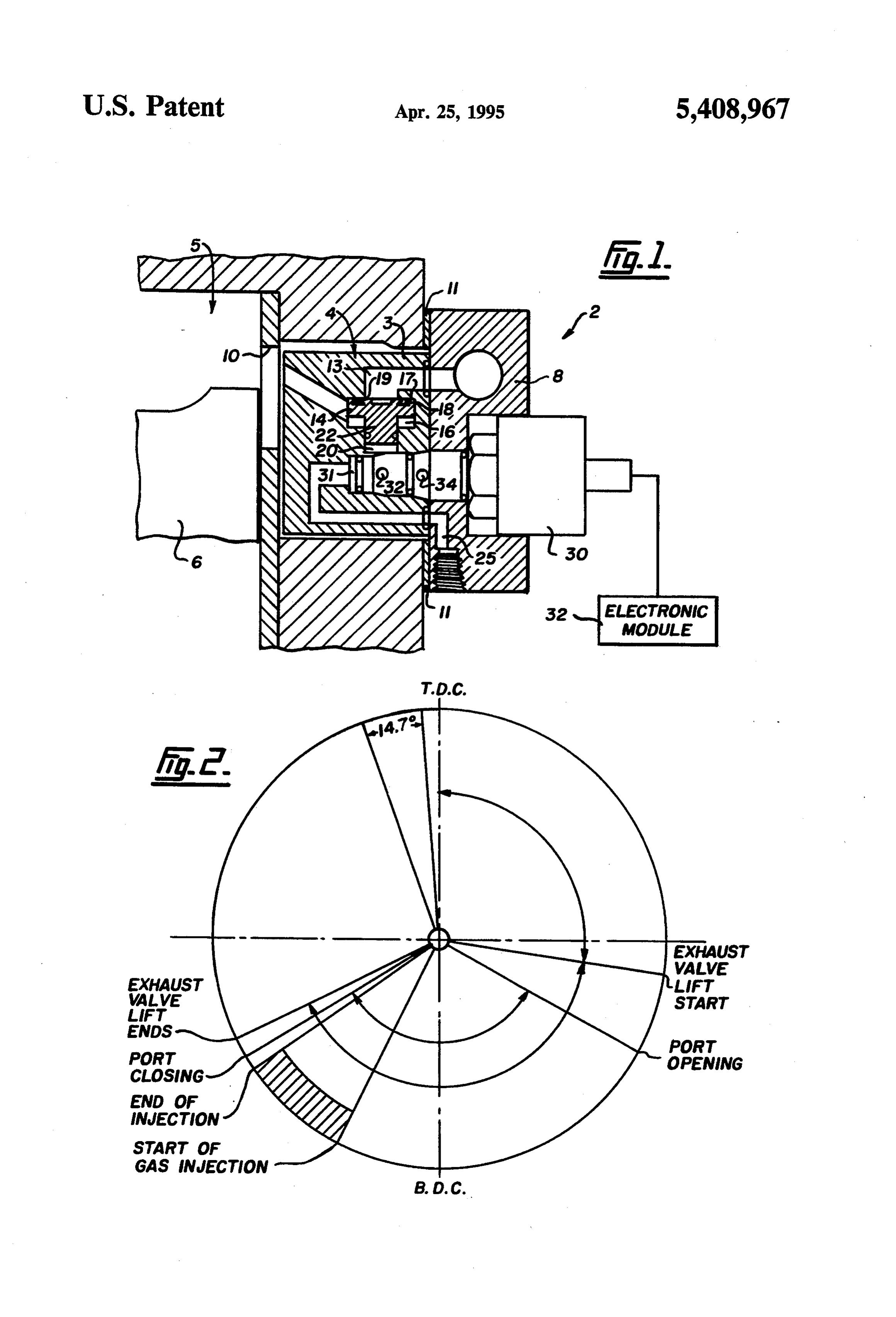
GASEOUS FUEL NJECTOR BRIEF DESCRIPTION OF THE DRAWINGS
Aspects of the present invention are illustrated,
FIELD OF THE INVENTION merely by way of example, in the accompanying draw This invention relates to a fuel injector for delivering ings, in which:
gaseous fuel to an engine. FIG. 1 is a detailed section view through a preferred embodiment of the fuel injector of the present inven
BACKGROUND OF THE INVENTION tion; and
FIG. 2 illustrates the typical timing diagram for an
Fuel injection systems are used to deliver fuel to 10 engine internal combustion engines. The majority of fuel injec fitted with the fuel injector of the present inven tion.
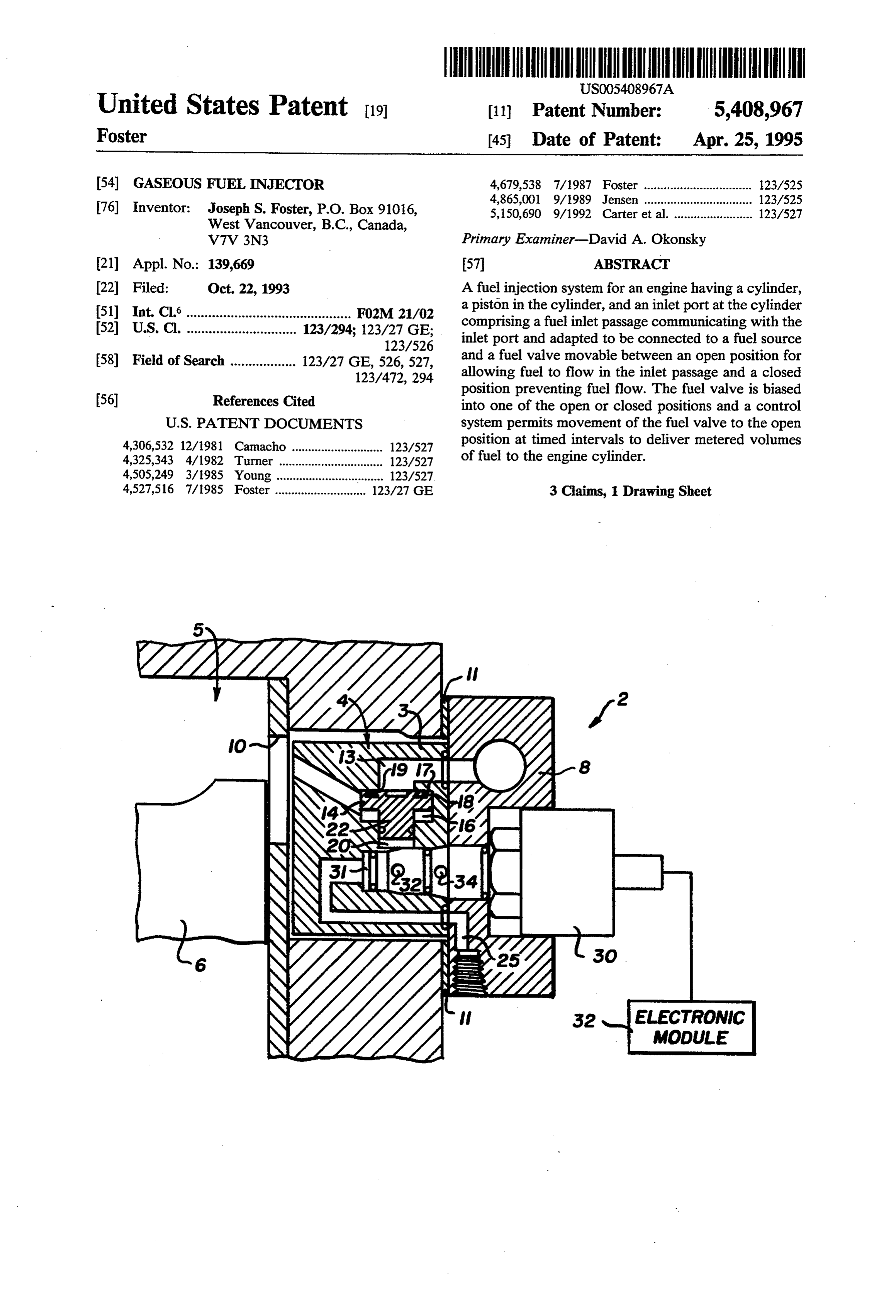
tion systems have been developed specifically to handle liquid fuels such as gasoline or diesel used in the engines DESCRIPTION OF THE PREFERRED of common passenger vehicles. Engines that run on EMBODIMENTS alternative gaseous fuels such as natural gas or propane 15 Referring to FIG. 1, there is shown a preferred en have also been developed. Applicant has developed a bodiment of the fuel injector 2 of the present invention dual fuel engine that runs on diesel and a gas fuel such attached to an engine block 4 that houses cylinder 5 and as propane or natural gas as disclosed in U.S. Pat. No. piston 6. Preferably, the fuel injector comprises a body 4,527,516 issued Jul. 9, 1985. 3 that is fastened to a header unit 8 and the combined Conversion kits have been developed for converting 20 assembly is fastened to the side of engine block 4 such gasoline or diesel (liquid fuel) engines to natural gas or that the injector body 3 extends into the block adjacent propane (gaseous fuel). Generally, these conversion kits inlet port 10 of cylinder 6. Gasket 11 forms a gas tight comprise a fuel/air mixer system for delivering the seal with engine block 4. The fuel injector system of the gaseous fuel to the engine cylinders. To be commer present invention is intended for use with both two cially acceptable, a conversion system must satisfy the 25 cycle and four cycle engines. While the operation of the following conditions: injector is the same for all engines, the shape and angle 1. Be capable of producing adequate horsepower. of the fuel inlet passage and the mounting method of the 2. Be capable of producing adequate torque. injector body 3 will be customized to suit the make, 3. Be capable of producing good thermal efficiency. model and fuelling requirements of the engine. 4. Provide good engine balance i.e. uniform cylinder 30 Fuel injector body 3 is formed with a fuel inlet pas firing pressures. sage 13 communicating inlet port 10 with a fuel source 5. Provide long service life. (not shown). The fuel source is preferably a pressurized 6. Provide low exhaust emission levels. container of gaseous fuel such as natural gas or propane. The above conditions are best satisfied by a fuel deliv 35 It has been determined that the injector of the present ery system that provides a precisely timed and metered invention performs well when the fuel delivered to the injection of gaseous fuel to each cylinder of the engine. injector is maintained at a relatively low pressure of 30
SUMMARY OF THE INVENTION
psi (207 kp) which is a practical pressure for a conven tional fuel delivery system.
The present invention provides a fuel injector that Within fuel inlet passage 13, there is a fuel valve satisfies the above conditions. The injector of the pres means in the form of piston 14. Piston 14 is movable ent invention provides a low pressure, high frequency between an open position against lower seat 16 for al injector that is actuated by a preprogrammed electronic lowing the pressurized gaseous fuel to flow in passage control module to provide a timed and metered volume 13 and a closed position against upper seat 17 to block of gaseous fuel to an internal combustion engine. 45 passage 13 and prevent fuel flow. O-ring 18 in the upper The present invention provides a fuel injection sys surface of piston 14 ensures a gas tight seal when the tem for an engine having a cylinder, a piston in the piston is in the closed position. O-ring 18 is preferably housed in an annular channel 19 of dovetailed cross-sec cylinder, and an inlet port at the cylinder comprising:
a fuel inlet passage communicating with the inlet port 50 tion formed in the upper surface of the piston. A poly and adapted to be connected to a fuel source; imide resin manufactured by Dupont under the trade fuel valve means movable between an open position mark resin
"Vespel' is suitable for forming piston 14. This provides a light-weight, high strength piston that for allowing fuel to flow in the inlet passage and a has very low inertia and can quickly move between the closed position preventing fuel flow; open and closed positions.
biasing means for biasing the fuel valve means into 55 The position of piston 14 is manipulated by biasing one of the open or closed positions; and means comprising a sealed chamber 20 in which a lower means for controlling the biasing means to permit end 22 of piston 14 is slidably mounted. Chamber 20 movement of the fuel valve means to the open communicates via passage 25 with a source of gas under position at timed intervals to deliver a metered pressure, preferably, compressed air. Therefore, cham volume of fuel to the engine cylinder. ber 20 is normally pressurized to exert a force on the The fuel injector of the present invention delivers piston 14 to bias the piston into the closed position to pressurized gaseous fuel to an internal combustion en prevent gaseous fuel flow. Compressed air at 100 psi gine that can be of two cycle and four cycle design. The (690 kp) has been found to work well in testing of the fuel injector is particularly well suited to operation with fuel injector of the present invention. a two cycle diesel engine and will allow such an engine 65 The pressurization of chamber 20 is preferably con to use natural gas or propane as a primary fuel to oper trolled by a second valve in the form high speed sole ate safely, efficiently and with adequate power and noid valve 30. Solenoid valve 30 is in turn controlled via torque. a control signal that originates in a pre-programmed
Page 4
electronic module 32. Solenoid valve 30 and its control the combustion air inlet cycle is complete. For a 2 module 32 are commercially available products. stroke engine, the end of the inlet air cycle occurs when Solenoid valve 30 is positioned within passage 25 and the rising piston closes of the inlet port, and for a 4 is formed with a central longitudinal passage having an stroke engine when the inlet valve closes. It follows that inlet port 31, a second port 32 that communicates with the amount of time for gaseous fuel injection is ex chamber 20, and a third port 34 that exhausts to atmo tremely short, eg. about 1/400 of a second. Prototype sphere. By default, inlet port 31 and second port 32 are testing also shows that for good thermal efficiency, open and third port 34 is closed such that solenoid valve injection timing should be retarded at low engine speeds 30 directs compressed air to chamber 20 to pressurize and advanced for high engine speeds. This injection the chamber and bias piston 14 to the closed position. 10 timing is easily preprogrammed into the controlling On a signal from the electronic module, solenoid electronic module.
valve 30 is energized to close off inlet port 31 and open The fuel injector of the present invention has also third port 34, thus connecting the second and third been ports to release the air in chamber 20 and depressurize to be designed self to minimize wear on impact surfaces and compensating for any wear that might occur.
the chamber. This allows piston 14 to move into cham 15 Although the present invention ber 20 to open fuel inlet passage 13. In fact, the pressur some detail by way of example forhaspurposes been described in ized gas within fuel inlet passage 13 ensures that piston and understanding, it will be apparent thatof certainclarity 14 moves very quickly to the open position. Passage 13 changes and modifications may be practised within the remains open a period to deliver an appropriate amount of gaseous fuel under pressure to the cylinder just be 20 scope
of the appended claims.
claim:
fore engine piston 6 closes off inlet port 10 of the cylin der. At the end of the injection period, solenoid valve ing1.aAcylinder, gaseous fuel injection system for an engine hav 30 is de-energized by the electronic module to close at the cylinderacomprising:
piston in the cylinder, and an inlet port third port 34 and open inlet port 31 allowing second port 32 to pressurize chamber 20, moving piston 14 to 25 a fuel inlet passage communicating with the inlet port the closed position to shut off gaseous fuel flow. for connection to a gaseous fuel source under pres This entire cycle of operation is repeated for each Sure;
power stroke of the engine. At 2100 rpm, the fuel injec fuel valve means movable between an open position tion cycle repeats 35 times per second for a two cycle for allowing fuel to flow in the inlet passage and a engine and 17 times per second for a four cycle engine. 30 closed position preventing fuel flow; The fuel injector of the present invention uses a fuel biasing means comprising a sealed chamber adjacent valve (piston 14) that has very low inertia to accommo the fuel valve means that is pressurizable to exert a date the rapid movements between open and closed force on the fuel valve means to bias the fuel valve positions that happen each cycle. Also the fuel valve means into the closed position; and (piston 14) is well sealed to prevent gas leaks into the 35means for controlling the biasing means comprising engine that would cause a loss of thermal efficiency and second valve means to reduce pressure in the an increase in undesirable exhaust emissions. sealed chamber at timed intervals such that the The electronic module is programmed to allow for pressurized gaseous fuel acts to move the fuel valve the proper timing and duration of the fuel injection means to the open position to deliver fuel to the pulse. The engine timing diagram shown in FIG. 2 engine cylinder via the fuel inlet passage. emphasizes that the valve timing of the engine is not in 2. A fuel injection system as claimed in claim 1 in any way changed by the use of the fuel injection system which the second valve means comprises a solenoid of the present invention. The valve timing diagram is valve controlled a preprogrammed electronic module. entirely conventional for a two cycle engine. For good 3. A fuel injection system as claimed in claim 1 in thermal efficiency, the gaseous fuel must be injected 45 which the fuel valve means comprises a piston that is after the scavenge cycle is virtually complete, so that formed from a high strength, light weight plastic. raw fuel is not discharged with exhaust gases, but before
Provenance
- Collection
- Cited prior art
- Original PDF
- patentimages.storage.googleapis.com →
- Filed
- 1993-10-22
- Pages
- 4
- Method
- pdftotext (the PDF's own text layer) + pdftoppm 300dpi page scans
- Source
- Google Patents bibliographic record
- Granted
- 1995-04-25
- Inventors
- Joseph S. Foster
- Transcribed from
- patentimages.storage.googleapis.com →