patent · US5488932
Gaseous fuel enriching subsystem
6 February 1996
Page 1 — bibliographic record
III III IIII
United States Patent (19) 11 Patent Number: 5,488,932 Serafini 45 Date of Patent: Feb. 6, 1996 54) GASEOUS FUEL ENRICHING SUBSYSTEM Primary Examiner-Erick R. Solis Attorney, Agent, or Firm-M. K. Silverman 76 Inventor: Joseph Serafini, 387 Lincoln Ave.,
Newark, N.J. 07104 (57) ABSTRACT
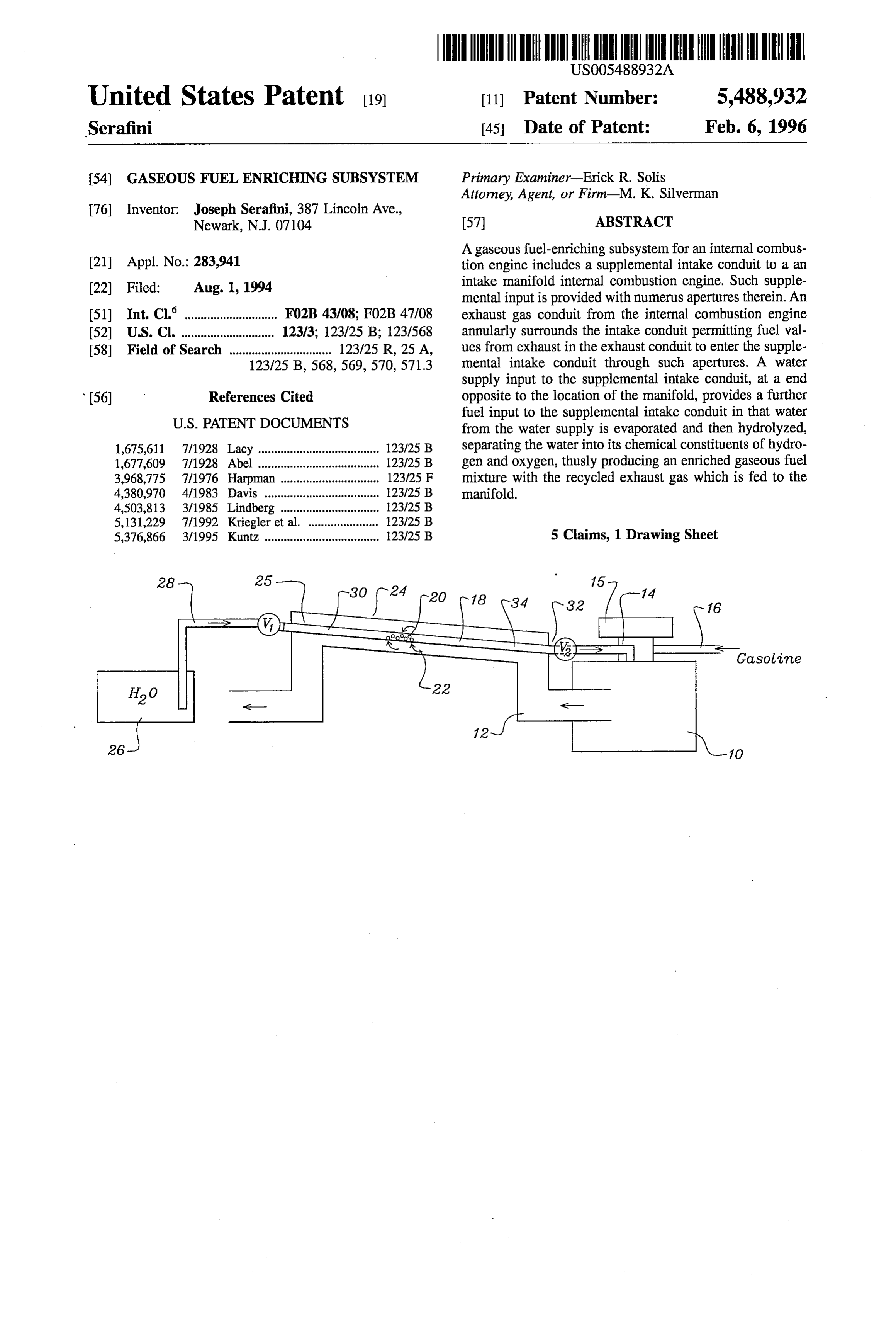
A gaseous fuel-enriching subsystem for an internal combus (21) Appl. No.: 283,941 tion engine includes a supplemental intake conduit to a an (22 Filed: Aug. 1, 1994 intake manifold internal combustion engine. Such supple mental input is provided with numerus apertures therein. An (51) Int. Cl.' ............................. F02B 43/08; FO2B 47/08 exhaust gas conduit from the internal combustion engine 52 U.S. Cl. ............................. 123/3; 123/25B; 123/568 annularly surrounds the intake conduit permitting fuel val 58) Field of Search ................................ 123/25R, 25 A, ues from exhaust in the exhaust conduit to enter the supple 123/25 B, 568, 569,570,571.3 mental intake conduit through such apertures. A water supply input to the supplemental intake conduit, at a end 56) References Cited opposite to the location of the manifold, provides a further fuel input to the supplemental intake conduit in that water
1,675,611 7/1928 Lacy ...................................... 123/25 B separating the water into its chemical constituents of hydro 1,677,609 7/1928 Abel ..... ... 123/25B gen and oxygen, thusly producing an enriched gaseous fuel 3,968,775 7/1976 Harpman ... 123/25 F mixture with the recycled exhaust gas which is fed to the 4,380,970 4/1983 Davis ........ ... 23/25 B manifold.
4,503,813 3/1985 Lindberg ....... ... 123/25 B 5,131,229 7/1992 Kriegler et al. ... 123/25 B 5,376,866 3/1995 Kuntz .................................... 123/25 B 5 Claims, 1 Drawing Sheet
Gasoline
Page 2
Drawing sheet — no readable text.
Page 3
GASEOUS FUEL ENRICHING SUBSYSTEM input to the internal combustion engine is a combination of the recycled fuel values of the exhaust gas stream and the
BACKGROUND OF THE INVENTION gaseous hydrogen and oxygen derivative of the chemical Separation of said water into its constituent elements. This
The present invention relates an internal-combustion gives rise to a significant and cost-effective performance engine and, more particularly, to an internal combustion enhancement of the internal combustion engine. engine provided with a particularly exhaust gas and external It is accordingly an object of the present invention to fuel enriching subsystem. The invention further relates to an provide a safe, economical and effective gas turbocharger exhaust gas recycling means, the effect of which is to permit system for an internal combustion engine. hydrocarbon values or exhaust gas to be utilized by the he 10 It is another object to provide a means of recycling unused internal combustion engine. fuel values in an exhaust gas stream from an internal Proposals have appeared in the prior art, involving the combustion engine.
utilization of exhaust gas and the pressure thereof to com It is a further object of the invention to provide a gaseous press intake air before its introduction into the combustion fuel enriching subsystem combining the fuel values of chamber of the engine. Such a supercharger is considered 15 exhaust gas recycling and the fuel values of hydrolyzed advantageous over so-called turbo-superchargers because it provides a high supercharging effect under various engine water vapor.
conditions including low speed operation. An improvement It is a yet further object to provide a gaseous fuel teaching such an engine intake device is taught in U.S. Pat. enriching subsystem which will reduce undesirable emis No. 4,702,218 (1987) to Yoshioka, entitled Engine intake 20 sions from an internal combustion engine while increasing System Having a Pressure Wave Supercharger. The teaching fuel efficiency.
this reference is that of the use of pressure differentials The above and yet other objects and advantages of the between the exhaust outlet and the engine intake can be used present invention will become apparent from the hereinafter to accomplish a more efficient burning of the engine fuel. set forth Brief Description of the Drawings, Detailed U.S. Pat. No. 5,131,229 (1992) to Kriegler, entitled linter 25 Description of the Invention and claims appended herewith. nal Combustion Engine with Exhaust Gas Turbocharger teaches the use of cooling techniques to accomplish recy BRIEF DESCRIPTION OF THE DRAWENGS cling of uncombusted fuel values from the exhaust gas
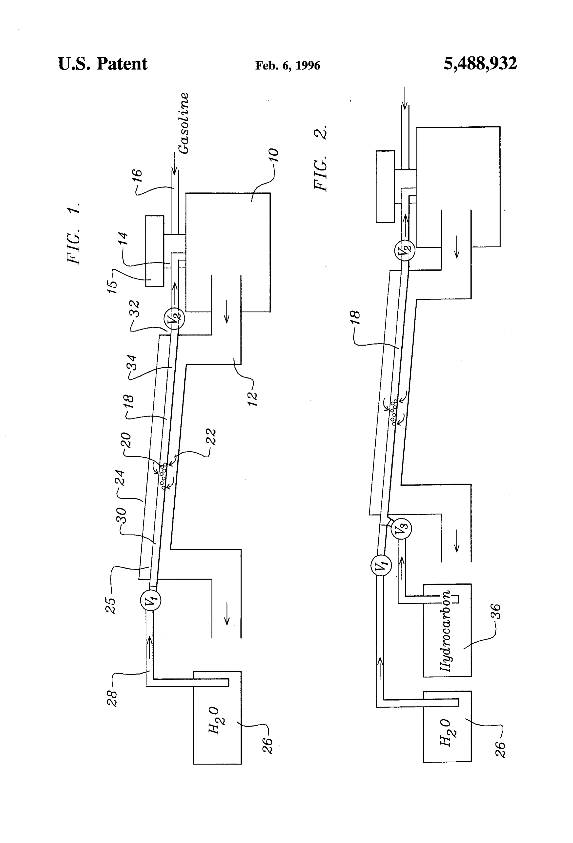
Stream. FIG. 1 is a schematic view of a first embodiment of the
In addition, the instant invention relates to a gaseous fuel inventive gaseous fuel enriching subsystem. enriching subsystem which is not reliant on cooling and is FIG. 2 is a schematic view of a second embodiment of the not primarily reliant upon pressure differentials between the invention.
engine exhaust and the engine intake. Rather, the invention, as is more fully set forth below, is directed to a system 35 DETAILED DESCRIPTION OF THE which, in addition to utilizing uncombusted fuel within the INVENTION exhaust, adds thereto hydrolyzed water to enrich the thermal values of a gaseous mixture of auxiliary fuels provided to the With reference to the view of FIG. 1 there is shown an engine. internal combustion engine 10 including therein an exhaust conduit 12 and an intake manifold 14. Further shown is
SUMMARY OF THE INVENTION gasoline fuel intake 16, from the fuel pump (not shown), to said manifold 14.
There is provided a fuel enriching subsystem for an With further reference to FIG. 1 there is shown a supple internal combustion engine which includes a separate and mental intake conduit 18 which, as may be noted, is pro independent fuel intake to the intake manifold of the engine.
There is, more particularly, furnished, annularly within the 45 vided with a multiplicity of apertures 20. The function of such apertures is to permit the lower gas pressure, i.e., exhaust gas conduit, an engine intake conduit having therein relative vacuum that exists within said supplemental conduit a multiplicity of apertures, such that a relative negative 18 to draw substantial portions of exhaust gas 22 from pressure, i.e., vacuum, within said supplemental conduit, exhaust conduit 12 into said conduit 18 through said aper relative to the pressure within said circumferentially sur tures 20. It is to be understood that a central portion 24 of rounding exhaust gas conduit, will enable a substantial 50 exhaust conduit 12 is annularly disposed about supplemental proportion of the exhaust gas to be drawn through said apertures and into said supplemental intake. At an end of intake conduit 18 which is tilted upward at its distal end 25 said supplemental intake distal from a proximal end thereof relative to its proximal end 32. It is, accordingly, to be appreciated that the use of apertures 20 permit recycling of which is in fluid communication with the intake manifold, uncombusted fluid values within the exhaust gas stream, there is provided a source of water which is permitted to 55 through conduit 18, to manifold 14 and therefrom into selectively enter said distal end of said supplemental conduit engine 10.
in a limited quantity which, as it passes through said apertured supplemental conduit in the direction of said As a source of added power, at a low incremental system manifold, is initially evaporated into gaseous form and, cost, there is provided a water source 16 which, as is thereafter, resultant from a temperature in excess of 700 60 indicated by arrow 28, is permitted to selectively enter degrees Fahrenheit to which said supplemental intake is conduit 18 through the operation of valve V1. elevated, hydrolyzed into its constituent chemical compo Due to the high temperature, that is, a temperature in nents of oxygen and hydrogen. Similarly, carbon monoxide, excess of 700 degrees which is generated by the exhaust gas which is drawn through the apertures into the supplemental within conduit 12, supplemental conduit 18 will be elevated intake conduit, physically adheres to the molecules of said 65 to a considerable temperature. This temperature is sufficient oxygen and hydrogen, to thereby modulate the rate of to vaporize water within region 30 of conduit 18 and, further, burning thereof. Accordingly, the resultant supplemental toward proximal end 32, to cause the hydrolysis in region34
Page 4
of such water vapor into its chemical constituents of oxygen Patent of the U.S. is:
and hydrogen. 1. A gaseous fuel enriching subsystem for an internal Carbon monoxide, which is drawn into apertures 20 as a combustion engine comprising:
part of the exhaust gas 22, will physically adhere, as by ionic (a) a supplemental intake conduit to an intake manifold of bonding, to molecules of said oxygen and hydrogen to said internal combustion engine, said conduit having a thereby modulate the rate of burning thereof. The result is, multiplicity of apertures therein; accordingly, that of a supplemental fuel input, in which a (b) an exhaust gas conduit from said internal combustion combination of (1) uncombusted fuel values from gasoline engine, said conduit annularly surrounding said intake and (2) hydrogen and oxygen from hydrolyzed water vapor, are all inputted to a normally open safety valve V2 and, 10 conduit in which gaseous exhaust from said exhaust therefrom, in a selectable manner, furnished to manifold 14 conduit is through said apertures, maintained in fluid where a mixture with atomized gasoline from fuel intake 16 communication with an interior of said supplemental will occur, the result thereof being a highly enriched fuel intake conduit; and input to engine 10. (c) a water supply input to said supplemental intake With reference to FIG. 2, there is shown a second embodi 15 conduit at an end of said conduit opposite to said intake ement of the invention in which a tank 36 for the contain manifold, ment of a hydrocarbon such as oil is provided so that, whereby thermal values from said exhaust gas conduit, through valve V3, its thermal values may be added to yet imparted to said supplemental intake, will elevate the tem further enrich the mixture of gaseous fuels carried within 20 perature of said water, firstly evaporating the same and supplemental intake 18, to valve V2 and to the input to subsequently, hydrolyzing said water prior to its entry into manifold 14. said manifold, this producing a gaseous mixture with fuel It is also noted that, in a further embodiment, the hydro value of said exhaust as entering said supplemental intake carbon fuel of tank 36 may constitute the sole fuel source through said apertures.
required to operate engine 10. 2. The system as recited as recited in claim 1, further 25 comprising:
As above noted, it is advantageous to position distal end 25 of supplemental conduit 18 at a higher level than proxi (a) valve means in fluid communication with an output of mal end 32. It has been found that such an orientation of the said water supply and an input to said supplemental distal end relative to the proximal end of conduit 18 enables intake conduit; and gravity to assist the negative (suction) pressure within 30 (b) valve means in fluid communication with an output of conduit 18 to thereby facilitate the movement of the gaseous said supplemental intake conduit and an input to said mixture, which would otherwise attempt to advance toward manifold.
end 25, into value the manifold 14. 3. The system as recited in claim 2, in which an elevation While there has been shown and described the preferred of an end of said supplemental intake conduit nearest to said embodiment of the instant invention it is to be appreciated 35 water supply valve defines a higher elevation than an end of that the invention may be embodied otherwise than is herein said supplemental intake conduit nearest said manifold. specifically shown and described and that, within said 4. The system as recited in claim 1, further comprising: embodiment, certain changes may be made in the form and an auxiliary fuel input to said intake conduit and valve arrangement of the parts without departing from the under means therewith.
lying ideas of principles of this invention as sent forth in the 40 5. The system as recited in claim 4, in which said auxiliary claims appended herewith. fuel comprises oil.
Having thus described my invention what I claim as new, useful and non-obvious and, accordingly, secure by Letters
Provenance
- Collection
- Cited prior art
- Original PDF
- patentimages.storage.googleapis.com →
- Filed
- 1994-08-01
- Pages
- 4
- Method
- pdftotext (the PDF's own text layer) + pdftoppm 300dpi page scans
- Source
- Google Patents bibliographic record
- Granted
- 1996-02-06
- Inventors
- Joseph Serafini
- Transcribed from
- patentimages.storage.googleapis.com →