patent · US3477937
Apparatus for the electrowinning of manganese
11 November 1969
Page 1
Drawing sheet — no readable text.
Page 2
Drawing sheet — no readable text.
Page 3
Drawing sheet — no readable text.
Page 4
Nov. 11, 1969 D. E. GULLETT ET All- 3,477,937
APPARATUS FOR THE ELECTROWINNING OF MANGANESE
Filed March 1, 1966 4. Sheets-Sheet 4
SSSN
ANOLYE
EACHING
UNT
NVENORS:
DAVID E. GULLETT
EDMOND F. REYNOLDS
Page 5
United States Patent Office Patented Nov. 11, 1969
ficiency, high quality plating. However, when each cath
APPARATUS FOR THE ELECTROWINNING ode plate is surrounded with an individual diaphragm OF MANGANESE to form a separate cathode compartment separately Sup David E. Gullett and Edmond F. Reynolds, Knoxville, plied with catholyte, we have found that unavoidable dif Tenn., assignors to Foote Mineral Company, Exton, Pa., 5 ferences a corporation of Pennsylvania in temperature and manganese concentration in the catholytes inside the several cathode compartments
Filed Mar. 11, 1966, Ser. No. 533,664 generally cause inferior plating in at least some of the Inf. C. B.01k 3/10; C22d 1/24; C23b 5/74 cells even though it may be satisfactory in others. More U.S. C. 204-263 10 Claims particularly, while the proper average manganese concen 0. tration can often be provided in the catholyte supply
ABSTRACT OF THE DISCLOSURE which is distributed to the various cathode compartments, departures from this optimum manganese concentration
Apparatus for the electrowinning of manganese em generally occur in various of the individual cathode com ploying a plurality of alternating cathode plates and anode partments; this generally reduces directly the plating ef elements in a manganese-plating bath, which apparatus 15 ficiency in such compartments and also increases the rate utilizes an electrolyte-pervious diaphragm of Woven tex of formation of undesired solid byproducts commonly tile material to form a single catholyte compartment known as "pink salts' which tend to plug the diaphragm, which separates the cathode elements from the anode change the effective resistance of the individual plating elements and which is spaced from the cathode elements cell, and thereby also reduce plating efficiency. Where to permit free circulation of electrolyte inside the catho 20 such "pink salts' are formed in large quantities, they may lyte compartment between the major surfaces of the dif in fact directly contaminate the cathode plates. Again, ferent cathode elements. A supporting frame supports the while average temperature of the catholyte supplied to cathode elements for easy removal by withdrawal through the various catholyte compartments can generally be held the open top of the diaphragm, and holds the diaphragm near the optimum value, individual variations in the tem away from the major surfaces of each of the cathode ele 25 perature in the various cathode compartments commonly ments to permit the desired free circulation of the catho occur and result in inferior plating, including so-called lyte electrolyte. "tree' formation and in some cases in the excessive for mation and deposition of undesired solids.
This invention relates to diaphragms for use in elec 30 newAccordingly it is an object of our invention to provide and useful apparatus for use in electrolytic processes.
trolytic processes, particularly electrolytic plating, and to apparatus employing such diaphragms. In one specific forAnother object is to provide new and useful apparatus form, the invention relates particularly to diaphragms and upontheplural electrodeposition of materials, such as manganese, cathode elements.
apparatus for use in the electrodeposition of manganese.
In the electroplating art it is known to separate a cath 35 forAnother object is to provide new and useful apparatus electrolytically depositing a material upon plural cath ode element from an anode element during plating by ode elements between which are located a plurality of means of a porous diaphragm, to supply a suitable catho lyte to the side of the diaphragm on which the cathode anode elements.
Another object is to provide such apparatus which pro element is located, and to supply a suitable anolyte to vides more uniform conditions in the vicinity of the sev the other side of the diaphragm. The diaphragm serves 40 eral cathode elements and hence more uniform, and su to maintain the desired optimum electrolytic composi perior, electroplating upon these cathode elements. tions at the cathode and anode while permitting the neces A further object is to provide a new and useful dia sary ion migration. In commercial cells for the large phragm arrangement for use in electrolytic processes. scale plating of materials it is common, and usually a Another object is to provide such a diaphragm which practical necessity, to employ a series of mutually-spaced 45 enhances cathode elements with anode elements positioned be around thetheseveral uniformity of conditions in the electrolyte cathode elements and thus improves tween them, and in such cases it is known to provide a the quality and efficiency of electroplating. separate diaphragm around each cathode element and to A further object is to provide new and useful dia supply each such individual diaphragm with a separate flow of catholyte by way of appropriate supply tubes ex 50 phragm manganese.
arrangements for use in the electrodeposition of tending from a reservoir of catholyte.
However, with such arrangements it has often been These and other objects of the invention are achieved found that there is a very substantial difference between by the provision of a novel form of diaphragm and a novel form of apparatus for using it in electrolytic the plating actions produced in the various individual processes. More particularly, in accordance with the in diaphragms. Thus even though some of the cathode ele- : vention there is provided a diaphragm shaped to envelop ments may be plated in an optimum manner, other cath a plurality of cathode elements in a common cathode ode elements in the same commercial cell will com monly exhibit poor plating efficiency and poor quality compartment formed by the diaphragm, while separating the cathode elements from anode elements which are of plating, and excessive formation of byproducts may located in the space between the successive cathode ele occur which tends to plug up the diaphragms and in 60 ments. The diaphragm is shaped to permit circulation of some cases to contaminate the cathode elements them selves. These undesired effects arise primarily because of the catholyte between the various cathode elements through lack of uniformity in the temperatures and compositions formcommon cathode compartments. In one preferred the diaphragm comprises a plurality of pockets, each of the catholytes inside the various diaphragms.
Referring particularly to the type of process with spe 65 enveloping a different one of the cathode elements, one side of each pocket being open and communicating with cific reference to which the invention will be described in detail, it is known to produce manganese by depositing it culationa common chamber in the diaphragm which permits cir electrolytically on a series of cathode plates immersed in of of catholyte between the various pockets. A flow catholyte an electrolyte, using anode elements which are situated a flow of anolyte into the common cathode compartment and between the cathode plates. This geometric arrangement 70 vided. through the anode compartment is pro of interdigitated cathode plates and anode elements has the above-describedformdiaphragm
In another of the diaphragm, the pockets of been found commercially desirable in obtaining high ef rather than at one end only so asareto open at both ends comprise, in effect,
Page 6
a plurality of sleeves extending on opposite sides of one other forms of diaphragms and is a copolymer of vinyl of the cathode elements and each communicating at its chloride and acrylonitrile.
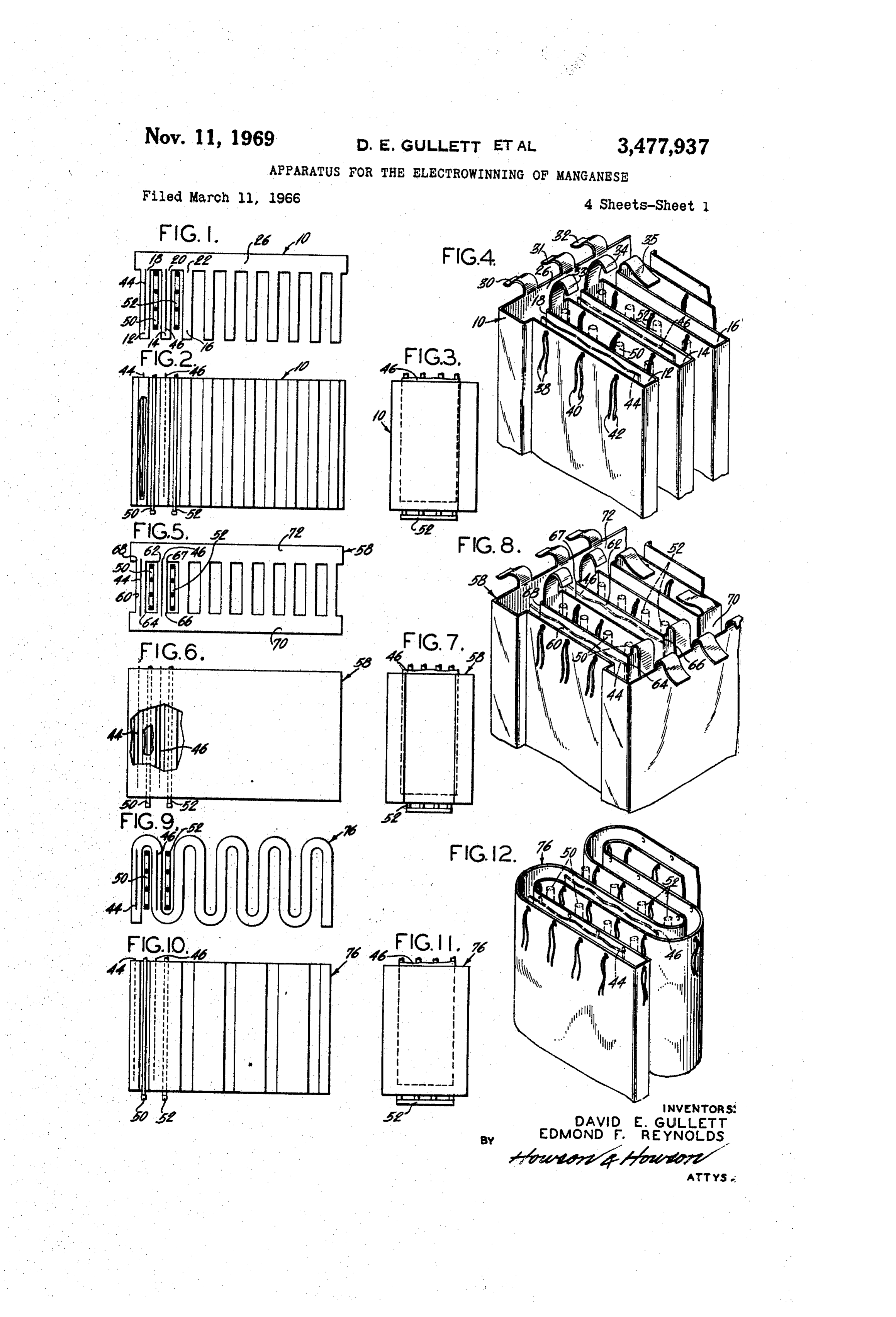
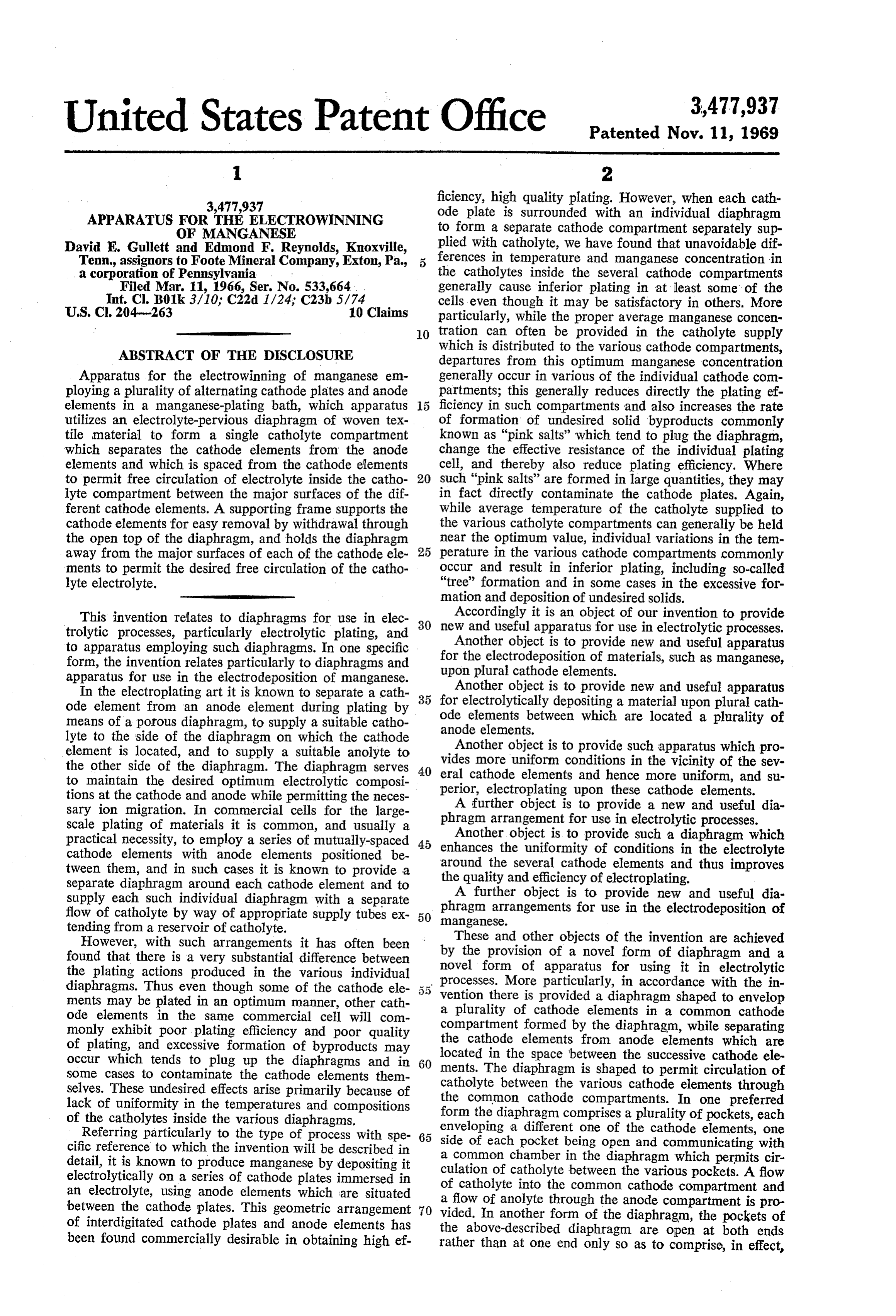
opposite open ends with a pair of common chambers The diaphragm 10 comprises a plurality of pockets. Such within the diaphragm, the two common chambers serv as 12, 14 and 16 of rectangular cross-section which are ing to interconnect the openings in the several sleeves. In open at the top and are also open at their respective rear still another form the invention may utilize for the dia ward sides such as 18, 20 and 22. The open sides of the phragm a continuous, sinuous, tubular sheath following individual pockets open into, and freely communicate a path which passes back and forth through the array with, a common chamber portion 26 of the diaphragm 10 of anode and cathode elements and enveloping all of the which extends the full length of the assembly of pockets cathode elements in sequence on their opposite sides; a and also the full height of each pocket. Such a diaphragm flow of catholyte is then supplied to the interior of the may be made by cutting appropriately shaped-pieces of sheath so that a circulation of catholyte occurs between diaphragm material and sewing them together, with ap the various cathode elements, propriate cementing along the Seams if desired, in the Utilizing such diaphragm arrangements in which the cathode elements are enclosed in a common catholyte manner referably which will be apparent to one skilled in the art.
the seams are sewed externally and then the compartment by a single diaphragm, it has been found entire diaphragm that superior results are obtained, apparently due to the vided (see FIG. 4)turned inside out. Also preferably pro
greater uniformity of the composition and temperature and 35 and tie strings such as 38, 40 and 42 for attach of the catholyte adjacent the various cathode elements, ing the diaphragm to a supporting frame to be described which in turn is apparently due to the mixing and cir 20 hereinafter.
culating of the catholyte in the common cathode com The cathode elements such as 44 and 46, each of which partment. In the specific case of the electroplating of may comprise an electrically-conductive rectangular plate, manganese, this has resulted in a greater uniformity of are suspended in the pockets such as 12, 14, one plate to high-quality, high-efficiency plating on the various cathode each pocket. Between the diaphragm pockets are SuS elements and a reduction in the rate of formation of pended the anode elements such as 50, 52, for example, undesired byproducts such as "pink salts.” one anode element between each pair of pockets, each Other objects and features of the invention will be more fully understood from a consideration of the following disposedelement anode typically comprising a group of vertically electrically-conductive rods. The manner of detailed description, taken in connection with the accom mounting of the cathode plates and the anode rods Will panying drawings, in which: 30 be particularly described with respect to other figures of FIGURES 1, 2, 3 and 4 are, respectively, top, front elevation, end elevation and fragmentary perspective views theWhen drawings.
in use, the interior of the diaphragm 10 is Sup of one preferred form of diaphragm arrangement in ac plied with a suitable catholyte, and the diaphragm there cordance with the invention, showing also preferred loca fore comprises a common catholyte compartment for all tions of the anode and cathode elements with respect of the cathode elements. The diaphragm is open at the to the diaphragm;
FIGURES 5, 6, 7 and 8 are, respectively, top, front top as closed is usual in electrolytic diaphragms, but is else elevation, end elevation and fragmentary perspective views where so as to separate all of the cathode ele ments from all of the anode elements. It will be appreci of another diaphragm arrangement in accordance with ated that this common catholyte compartment diaphragm the invention, showing also a preferred location of the 40 in which the individual cathode pockets communicate anode phragm; and cathode elements with respect to the dia with a common chamber 26 permits the desired circula FIGURES 9, 10, 11 and 12 are, respectively, top, front tion and uniform mixing of the catholyte which has been elevation, end elevation and fragmentary perspective views found to produce a substantially uniform temperature and composition of electrolyte around all of the cathode of a third diaphragm arrangement in accordance with the 45 elements, with resultant improvement in plating quality invention, showing also a preferred location of the anode and efficiency and with a reduction in generation of un and cathode elements with respect to the diaphragm; desired solid byproducts.
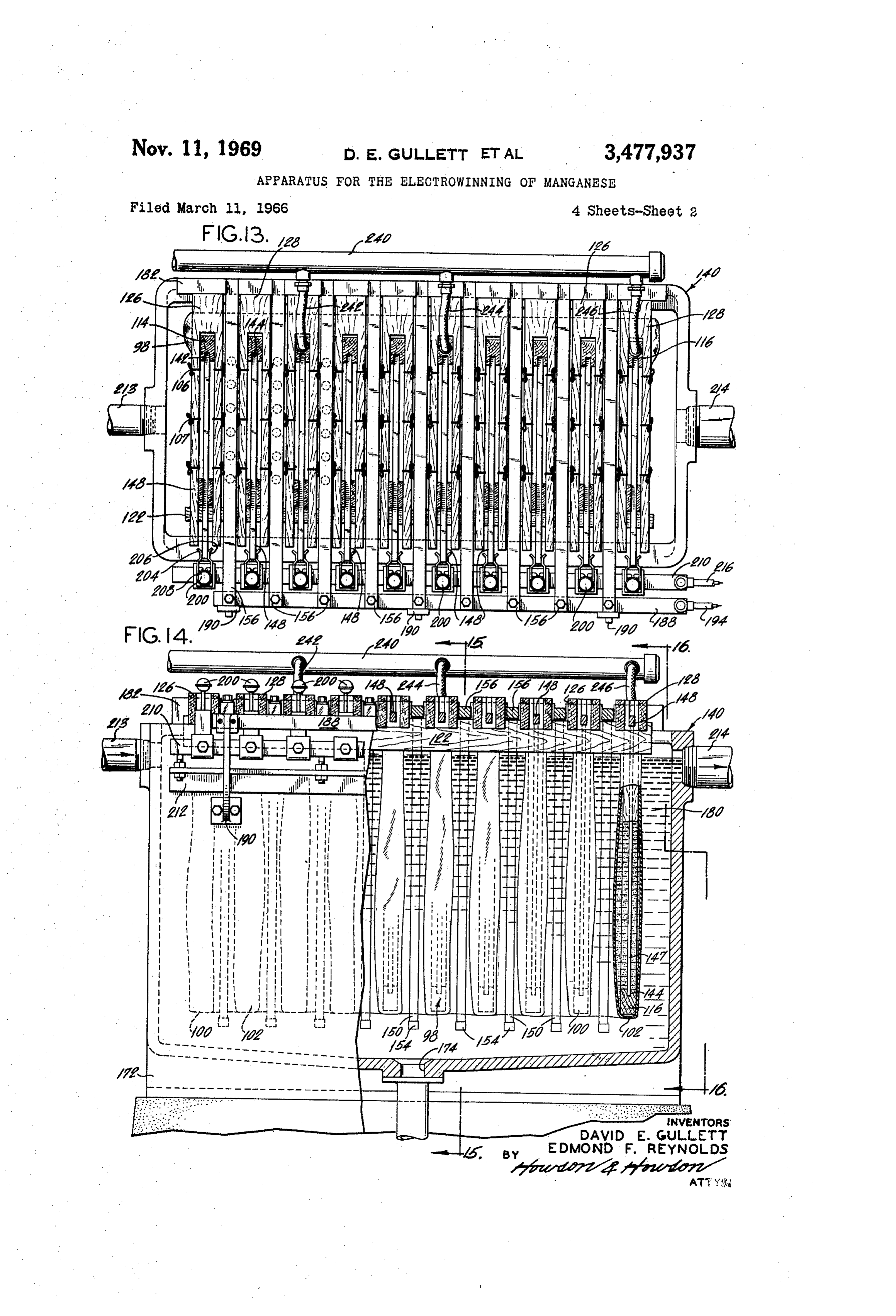
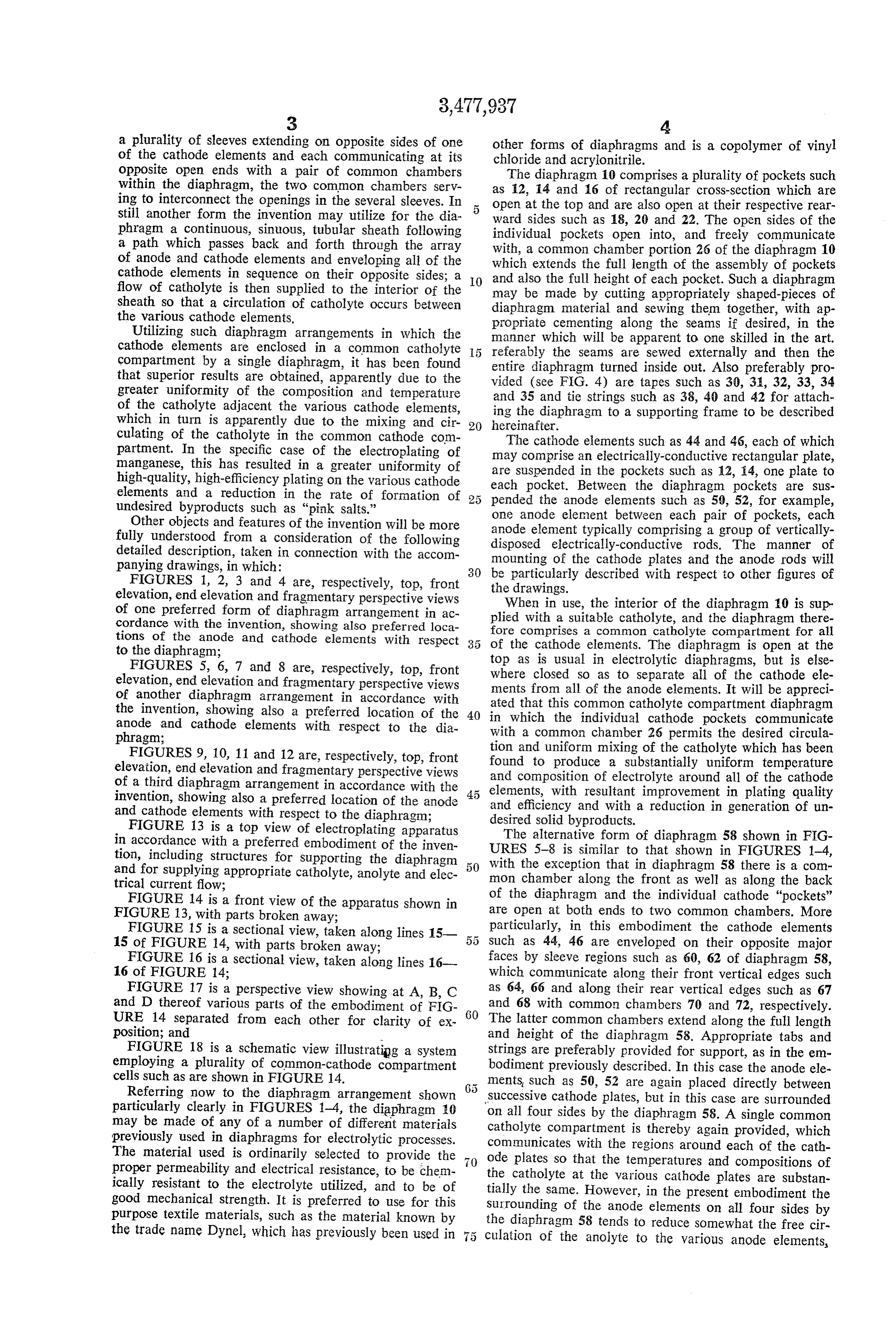
FIGURE 13 is a top view of electroplating apparatus The alternative form of diaphragm 58 shown in FIG in accordance with a preferred embodiment of the inven URES 5-8 is similar to that shown in FIGURES 1-4, tion, including structures for Supporting the diaphragm and for supplying appropriate catholyte, anolyte and elec 50 with the exception that in diaphragm 58 there is a com" mon chamber along the front as well as along the back trical current flow;
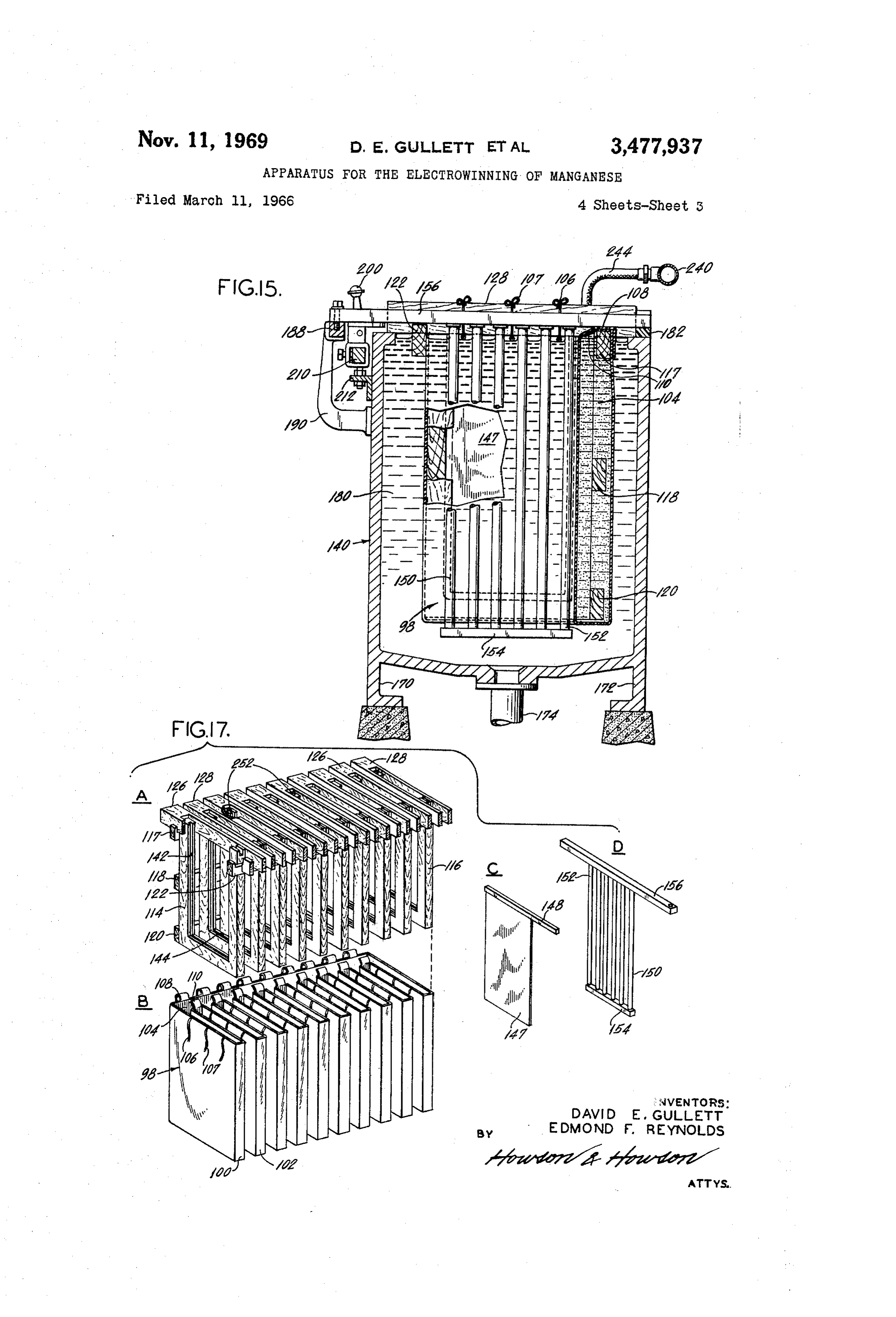
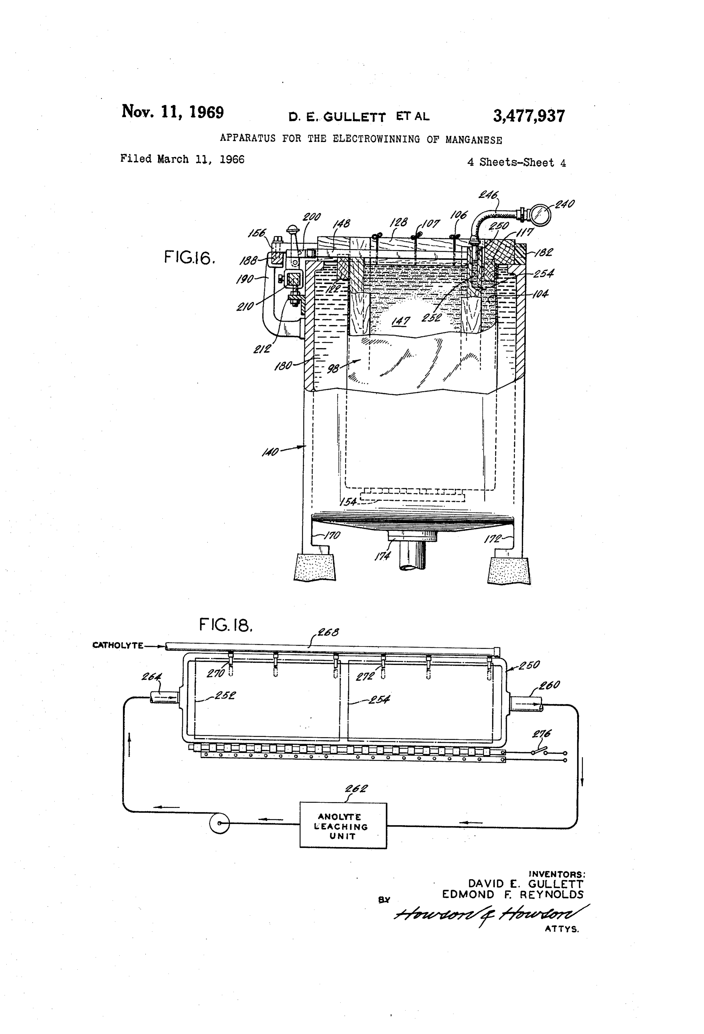
FIGURE 14 is a front view of the apparatus shown in are of the diaphragm and the individual cathode "pockets' FIGURE 13, with parts broken away; open at both ends to two common chambers. More FIGURE 15 is a sectional view, taken along lines 15 such particularly, in this embodiment the cathode elements 15 of FIGURE 14, with parts broken away; as 44, 46 are enveloped on their opposite major FIGURE 16 is a sectional view, taken along lines 16 faces by sleeve regions such as 60, 62 of diaphragm 58, 16 of FIGURE 14; which communicate along their front vertical edges such FIGURE 17 is a perspective view showing at A, B, C as 64, 66 and along their rear vertical edges such as 67 and D thereof various parts of the embodiment of FIG and 68 with common chambers 70 and 72, respectively. URE 14 separated from each other for clarity of ex 60 The latter common chambers extend along the full length position; and and height of the diaphragm 58. Appropriate tabs and FIGURE 18 is a schematic view illustrating a system strings are preferably provided for support, as in the em employing a plurality of common-cathode compartment bodiment previously described. In this case the anode ele cells such as are shown in FIGURE 14. ments, such as 50, 52 are again placed directly between Referring now to the diaphragm arrangement shown successive cathode plates, but in this case are surrounded particularly clearly in FIGURES 1-4, the diaphragm 10 on all four sides by the diaphragm 58. A single common may be made of any of a number of different materials catholyte compartment is thereby again provided, which previously used in diaphragms for electrolytic processes. communicates with the regions around each of the cath The material used is ordinarily selected to provide the ode plates so that the temperatures and compositions of proper permeability and electrical resistance, to be chem the catholyte at the various cathode plates are substan ically resistant to the electrolyte utilized, and to be of tially the same. However, in the present embodiment the good mechanical strength. It is preferred to use for this Surrounding of the anode elements on all four sides by purpose textile materials, such as the material known by the diaphragm 58 tends to reduce somewhat the free cir the trade name Dynel, which has previously been used in culation of the anolyte to the various anode elements,
Page 7
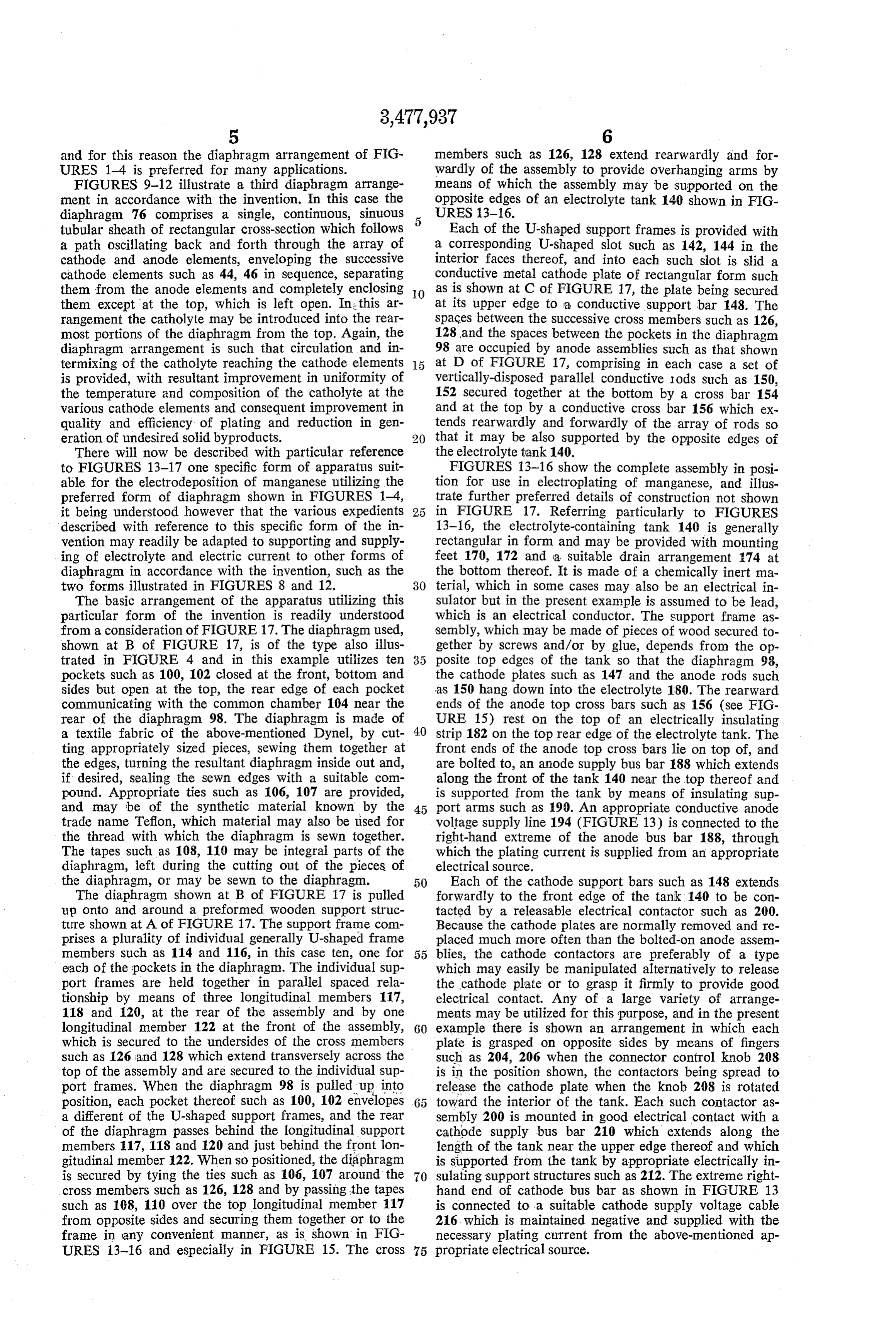
and for this reason the diaphragm arrangement of FIG members such as 126, 128 extend rearwardly and for URES 1-4 is preferred for many applications. wardly of the assembly to provide overhanging arms by FIGURES 9-12 illustrate a third diaphragm arrange means of which the assembly may be supported on the ment in accordance with the invention. In this case the opposite edges of an electrolyte tank 140 shown in FIG diaphragm 76 comprises a single, continuous, sinuous 5 URES 3-16.
tubular sheath of rectangular cross-section which follows Each of the U-shaped support frames is provided with a path oscillating back and forth through the array of a corresponding U-shaped slot such as 142, 144 in the cathode and anode elements, enveloping the successive interior faces thereof, and into each such slot is slid a cathode elements such as 44, 46 in sequence, separating conductive metal cathode plate of rectangular form such them from the anode elements and completely enclosing O as is shown at C of FIGURE 17, the plate being secured them except at the top, which is left open. In this ar at its upper edge to a conductive support bar 148. The rangement the catholyte may be introduced into the rear Spaces between the successive cross members such as 126, most portions of the diaphragm from the top. Again, the 128 and the spaces between the pockets in the diaphragm diaphragm arrangement is such that circulation and in 98 are occupied by anode assemblies such as that shown termixing of the catholyte reaching the cathode elements at D of FIGURE 17, comprising in each case a set of is provided, with resultant improvement in uniformity of Vertically-disposed parallel conductive iods such as 150, the temperature and composition of the catholyte at the 152 secured together at the bottom by a cross bar 154 various cathode elements and consequent improvement in and at the top by a conductive cross bar 156 which ex quality and efficiency of plating and reduction in gen tends rearwardly and forwardly of the array of rods so eration of undesired solid byproducts. that it may be also supported by the opposite edges of There will now be described with particular reference the electrolyte tank 140.
to FIGURES 13-17 one specific form of apparatus suit FIGURES 13-16 show the complete assembly in posi able for the electrodeposition of manganese utilizing the tion for use in electroplating of manganese, and illus preferred form of diaphragm shown in FIGURES 1-4, trate further preferred details of construction not shown it being understood however that the various expedients 25 in FIGURE 17. Referring particularly to FIGURES described with reference to this specific form of the in 13-16, the electrolyte-containing tank 140 is generally vention may readily be adapted to supporting and Supply rectangular in form and may be provided with mounting ing of electrolyte and electric current to other forms of feet 170, 172 and a suitable drain arrangement 174 at diaphragm in accordance with the invention, such as the the bottom thereof. It is made of a chemically inert ma two forms illustrated in FIGURES 8 and 12. 30 terial, which in some cases may also be an electrical in The basic arrangement of the apparatus utilizing this Sulator but in the present example is assumed to be lead, particular form of the invention is readily understood which is an electrical conductor. The support frame as from a consideration of FIGURE 7. The diaphragm used, Sembly, which may be made of pieces of wood secured to shown at B of FIGURE 17, is of the type also illus gether by screws and/or by glue, depends from the op trated in FIGURE 4 and in this example utilizes ten posite top edges of the tank so that the diaphragm 98, pockets such as 100, 102 closed at the front, bottom and the cathode plates such as 147 and the anode rods such sides but open at the top, the rear edge of each pocket as 150 hang down into the electrolyte 180. The rearward communicating with the common chamber 104 near the ends of the anode top cross bars such as 156 (see FIG rear of the diaphragm 98. The diaphragm is made of URE 15) rest on the top of an electrically insulating a textile fabric of the above-mentioned Dynel, by cut 40 Strip 182 on the top rear edge of the electrolyte tank. The ting appropriately sized pieces, sewing them together at front ends of the anode top cross bars lie on top of, and the edges, turning the resultant diaphragm inside out and, are bolted to, an anode supply bus bar 188 which extends if desired, sealing the sewn edges with a suitable com along the front of the tank 140 near the top thereof and pound. Appropriate ties such as 106, 107 are provided, is supported from the tank by means of insulating sup and may be of the synthetic material known by the 45 port arms such as 190. An appropriate conductive anode trade name Teflon, which material may also be lised for voltage supply line 194 (FIGURE. 13) is connected to the the thread with which the diaphragm is sewn together. right-hand extreme of the anode bus bar 188, through The tapes such as 108, 119 may be integral parts of the which the plating current is supplied from an appropriate diaphragm, left during the cutting out of the pieces of electrical source.
the diaphragm, or may be sewn to the diaphragm. 50 Each of the cathode support bars such as 148 extends The diaphragm shown at B of FIGURE 17 is pulled forwardly to the front edge of the tank 140 to be con up onto and around a preformed wooden support struc tacted by a releasable electrical contactor such as 200. ture shown at A of FIGURE 17. The support frame com Because the cathode plates are normally removed and re prises a plurality of individual generally U-shaped frame placed much more often than the bolted-on anode assem members such as 114 and 116, in this case ten, one for 5 5 blies, the cathode contactors are preferably of a type each of the pockets in the diaphragm. The individual sup which may easily be manipulated alternatively to release port frames are held together in parallel spaced rela the cathode plate or to grasp it firmly to provide good tionship by means of three longitudinal members 117, electrical contact. Any of a large variety of arrange 118 and 120, at the rear of the assembly and by one ments may be utilized for this purpose, and in the present longitudinal member 122 at the front of the assembly, 60 example there is shown an arrangement in which each which is secured to the undersides of the croSS members plate is grasped on opposite sides by means of fingers such as 126 and 128 which extend transversely across the such as 204, 206 when the connector control knob 208 top of the assembly and are secured to the individual Sup is in the position shown, the contactors being spread to port frames. When the diaphragm 98 is pulled up into release the cathode plate when the knob 208 is rotated position, each pocket thereof such as 100, 102 envelopes toward the interior of the tank. Each such contactor as a different of the U-shaped support frames, and the rear sembly 200 is mounted in good electrical contact with a of the diaphragm passes behind the longitudinal support cathode supply bus bar 210 which extends along the members 117, 118 and 120 and just behind the front lon length of the tank near the upper edge thereof and which gitudinal member 122. When so positioned, the diaphragm is supported from the tank by appropriate electrically in is secured by tying the ties such as 106, 107 around the 70 sulating support structures such as 212. The extreme right cross members such as 126, 128 and by passing the tapes hand end of cathode bus bar as shown in FIGURE 13 such as 108, 110 over the top longitudinal member 117 is connected to a suitable cathode supply voltage cable from opposite sides and securing them together or to the 216 which is maintained negative and supplied with the frame in any convenient manner, as is shown in FIG necessary plating current from the above-mentioned ap URES 13-16 and especially in FIGURE 15. The cross 75 propriate electrical source.
Page 8
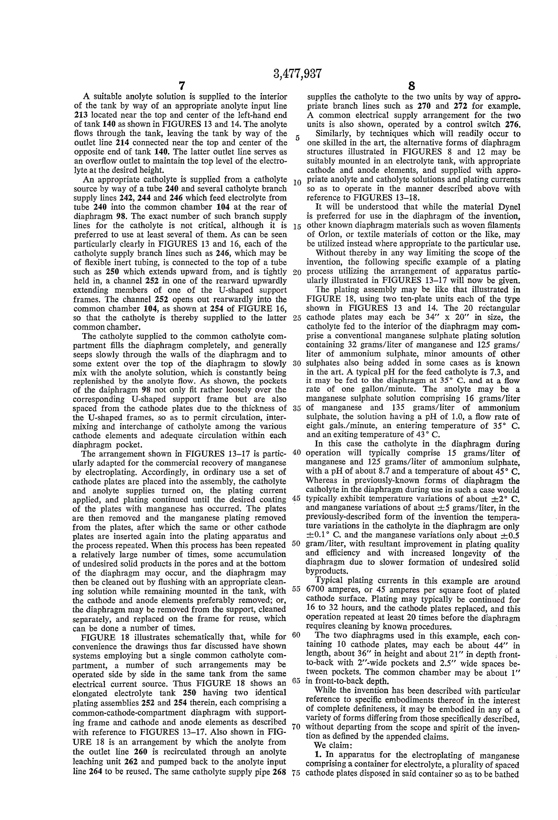
A suitable anolyte solution is supplied to the interior supplies the catholyte to the two units by way of appro of the tank by way of an appropriate anolyte input line priate branch lines such as 270 and 272 for example. 213 located near the top and center of the left-hand end A common electrical supply arrangement for the two of tank 140 as shown in FIGURES 13 and 14. The anolyte units is also shown, operated by a control switch 276. flows through the tank, leaving the tank by way of the 5 Similarly, by techniques which will readily occur to outlet line 214 connected near the top and center of the one skilled in the art, the alternative forms of diaphragm opposite end of tank 140. The latter outlet line serves as structures illustrated in FIGURES 8 and 12 may be an overflow outlet to maintain the top level of the electro suitably mounted in an electrolyte tank, with appropriate lyte at the desired height. cathode and anode elements, and supplied with appro An appropriate catholyte is supplied from a catholyte O priate anolyte and catholyte solutions and plating currents source by way of a tube 240 and several catholyte branch So as to operate in the manner described above with supply lines 242, 244 and 246 which feed electrolyte from reference to FIGURES 13-18.
tube 240 into the common chamber 104 at the rear of It will be understood that while the material Dynel diaphragm 98. The exact number of such branch supply is preferred for use in the diaphragm of the invention, lines for the catholyte is not critical, although it is other known diaphragm materials such as woven filaments preferred to use at least several of them. As can be seen of Orlon, or textile materials of cotton or the like, may particularly clearly in FIGURES 13 and 16, each of the be utilized instead where appropriate to the particular use. catholyte supply branch lines such as 246, which may be Without thereby in any way limiting the scope of the of flexible inert tubing, is connected to the top of a tube invention, the following specific example of a plating such as 250 which extends upward from, and is tightly 20 process utilizing the arrangement of apparatus partic held in, a channel 252 in one of the rearward upwardly ularly illustrated in FIGURES 13-17 will now be given. extending members of one of the U-shaped support The plating assembly may be like that illustrated in frames. The channel 252 opens out rearwardly into the FIGURE 18, using two ten-plate units each of the type common chamber 104, as shown at 254 of FIGURE 16, shown in FIGURES 13 and 14. The 20 rectangular So that the catholyte is thereby supplied to the latter cathode plates may each be 34' x 20' in size, the common chamber. catholyte fed to the interior of the diaphragm may com The catholyte supplied to the common catholyte com prise a conventional manganese sulphate plating solution partment fills the diaphragm completely, and generally containing 32 grams/liter of manganese and 125 grams/ seeps slowly through the walls of the diaphragm and to liter of ammonium Sulphate, minor amounts of other some extent over the top of the diaphragm to slowly 30 sulphates also being added in some cases as is known mix with the anolyte solution, which is constantly being in the art. A typical pH for the feed catholyte is 7.3, and replenished by the anolyte flow. As shown, the pockets it may be fed to the diaphragm at 35 C. and at a flow of the daiphragm 98 not only fit rather loosely over the rate of one gallon/minute. The anolyte may be a corresponding U-shaped support frame but are also manganese Sulphate solution comprising 16 grams/liter spaced from the cathode plates due to the thickness of of manganese and 135 grams/liter of ammonium the U-shaped frames, so as to permit circulation, inter Sulphate, the Solution having a pH of 1.0, a flow rate of mixing and interchange of catholyte among the various eight gals./minute, an entering temperature of 35° C. cathode elements and adequate circulation within each and an exiting temperature of 43° C. diaphragm pocket. In this case the catholyte in the diaphragm during The arrangement shown in FIGURES 13-17 is partic 40 operation will typically comprise 15 grams/liter of ularly adapted for the commercial recovery of manganese manganese and 125 grams/liter of ammonium sulphate, by electroplating. Accordingly, in ordinary use a set of with a pH of about 8.7 and a temperature of about 45° C. cathode plates are placed into the assembly, the catholyte Whereas in previously-known forms of diaphragm the and anolyte supplies turned on, the plating current catholyte in the diaphragm during use in such a case would applied, and plating continued until the desired coating 45 typically exhibit temperature variations of about 2° C. of the plates with manganese has occurred. The plates and manganese variations of about -5 grams/liter, in the are then removed and the manganese plating removed previously-described form of the invention the tempera from the plates, after which the same or other cathode ture variations in the catholyte in the diaphragm are only plates are inserted again into the plating apparatus and th:0.1 C. and the manganese variations only about 0.5 the process repeated. When this process has been repeated 50 gram/liter, with resultant improvement in plating quality a relatively large number of times, some accumulation and efficiency and with increased longevity of the of undesired solid products in the pores and at the bottom diaphragm due to slower formation of undesired solid of the diaphragm may occur, and the diaphragm may byproducts.
then be cleaned out by flushing with an appropriate clean 55 Typical plating currents in this example are around ing solution while remaining mounted in the tank, with 6700 amperes, or 45 amperes per square foot of plated the cathode and anode elements preferably removed; or, cathode surface. Plating may typically be continued for the diaphragm may be removed from the Support, cleaned 16 to 32 hours, and the cathode plates replaced, and this separately, and replaced on the frame for reuse, which operation repeated at least 20 times before the diaphragm can be done a number of times. requires cleaning by known procedures. FIGURE 18 illustrates schematically that, while for 60 The two diaphragms used in this example, each con convenience the drawings thus far discussed have shown taining 10 cathode plates, may each be about 44' in systems employing but a single common catholyte com length, about 36" in height and about 21' in depth front partment, a number of such arrangements may be to-back with 2'-wide pockets and 2.5" wide spaces be operated side by side in the same tank from the same tween pockets. The common chamber may be about 1' electrical current source. Thus FIGURE 18 shows an in front-to-back depth.
elongated electrolyte tank 250 having two identical While the invention has been described with particular plating assemblies 252 and 254 therein, each comprising areference to specific embodiments thereof in the interest common-cathode-compartment diaphragm with support of complete definiteness, it may be embodied in any of a variety of forms differing from those specifically described, ing frame and cathode and anode elements as described 70 without with reference to FIGURES 13-17. Also shown in FIG departing from the scope and spirit of the inven URE 18 is an arrangement by which the anolyte from tion as defined by the appended claims. We claim:
the outlet line 260 is recirculated through an anolyte 1. In apparatus for the electroplating of manganese leaching unit 262 and pumped back to the anolyte input comprising a container for electrolyte, a plurality of spaced line 264 to be reused. The same catholyte supply pipe 268 cathode plates disposed in said container so as to be bathed
Page 9
by electrolyte in said container, a plurality of anode ele spaced from both major surfaces of each of said ments disposed between and spaced from said plates, cathode plates thereby to provide for free circulation means for applying to said anode elements an electrical of said catholyte to said major surfaces of said plates; potential positive with respect to said cathode plates, elec and trolyte-pervious diaphragm means separating said cathode means for providing a flow of anolyte into and out of plates from said anode elements, means for supplying a 5 said container exterior of said common catholyte flow of catholyte into said container on the cathode side cmpartment.
of said diaphragm, and means for supplying a flow of 7. Apparatus in accordance with claim 6, in which said anolyte into and out of said container on the anode side common catholyte compartment comprises a plurality of of said diaphragm, the improvement according to which pockets each enveloping the bottom and three sides of one said diaphragm means comprises a diaphragm separating O of said cathode plates, and a common chamber communi said cathode plates from said anode elements and closed cating with said pockets at their fourth sides. on its sides and bottom to form a common catholyte com 8. Apparatus in accordance with claim 7, in which said partment enveloping said cathode plates, said diaphragm frame comprises a plurality of individual support frames, being spaced from the major faces of said plates to pro 15 one for each of said cathode plates, each of said support vide for unimpeded circulation of said catholyte to said frames being adapted to support its corresponding cathode plates and over both major faces thereof. plate for upward withdrawal thereof from said container 2. Apparatus in accordance with claim 1, in which said and to hold said diaphragm away from both major sur diaphragm defines a common catholyte compartment com faces of said corresponding cathode plate, said diaphragm prising a plurality of individual catholyte chambers each 20 being configured to fit loosely around the sides and bot enveloping a different one of said cathode plates and a tom of each of said support frames and to be secured common catholyte chamber of a volume large compared thereto.
with the volume of each of said individual catholyte cham 9. Electroplating apparatus, comprising: bers and freely communicating with each of said individ a plurality of cathode elements; ual catholyte chambers. 25 at least one anode element spaced from and between 3. Apparatus in accordance with claim 1, in which said different ones of said cathode elements; diaphragm is open at its top to permit insertion and with a porous diaphragm enveloping said cathode elements drawal of cathode plates into said diaphragm from the and separating each of them from said anode ele top of said apparatus. ment, said diaphragm being sufficiently spaced from 4. In the apparatus of claim 1, means supporting Said 30 said cathode elements to provide communication in diaphragm so as to hold it spaced from said major faces ternally thereof between each of said cathode ele of said cathode plates. ments, whereby electrolyte within said diaphragm can 5. Apparatus in accordance with claim 4, in which said circulate freely between different ones of said cathode supporting means comprises a rigid frame in said con elements but is restrained from circulating to said tainer. 35 anode element.
6. Apparatus for the electroplating of manganese, com 10. The apparatus of claim 9, in which said diaphragm prising: is of a textile fabric, and comprising support means for a container for a manganese-plating electrolyte; holding said diaphragm in said spaced position. a supporting frame in said container;
a plurality of vertical, parallel, spaced-apart cathode 40 References Cited plates removably mounted in a row on said frame UNITED STATES PATENTS and within said container, with their bottom ends spaced above the bottom of said container; 1,815,078 7/1931 Smith -------------- 204-253 a plurality of anode elements disposed between said 2,361,974 11/1944 Smith -------------- 204-260 cathode plates; 45 2,944,956 7/1960 Blue et al. ----- 204-296 XR means for applying to said anode elements a positive 3,337,443 8/1967 Raetzsch et al. ---- 204-258 XR potential with respect to said cathode plates; FOREIGN PATENTS a continuous open-topped electrolyte-pervious dia phragm separating said cathode plates from said anode 375,085 5/1923 Germany.
elements, enveloping the sides and bottom of each 50 JOHN H. MACK, Primary Examiner of said cathode plates, and enclosing all of said cathode plates in a common catholyte compartment; D. R. JORDAN, Assistant Examiner means for providing a flow of catholyte into said catho lyte compartments; U.S. Cl. X.R. said frame supporting said diaphragm and holding it 55 204-105, 257
Provenance
- Collection
- Cited prior art
- Original PDF
- patentimages.storage.googleapis.com →
- Filed
- 1966-03-11
- Pages
- 9
- Method
- pdftotext (the PDF's own text layer) + pdftoppm 300dpi page scans
- Source
- Google Patents bibliographic record
- Granted
- 1969-11-11
- Inventors
- David E Gullett; Edmond F Reynolds; Foote Mineral Co
- Transcribed from
- patentimages.storage.googleapis.com →