patent · US4395994
Fuel mixture heating device of an internal combustion engine
2 August 1983
Page 1 — bibliographic record
United States Patent (19) 11 4,395,994 Goto et al. 45 Aug. 2, 1983 54 FUELMIXTURE HEATING DEVICE OF AN 4,108,953 8/1978 Rocco ................................. 123/545 INTERNAL COMBUSTION ENGINE 4,242,999 1/1981 Hoser .................................. 123/548 4,246,880 /1981 Henke .. ... 123/549 75) Inventors: Shuji Goto; Kazuyoshi Tasaka; 4,300,513 11/1981 Ray .. ... 123/545 Masaru Tanaka, all of Toyota, Japan 4,308,845 1/1982 Sarto ................................... 123/549 73) Assignee: Toyota Jidosha Kogyo Kabushiki FOREIGN PATENT DOCUMENTS Kaisha, Aichi, Japan 475676 6/1915 France ................................ 219/207 (21) Appl. No.: 200,098 828061 5/1938 France ................................ 123/545 (22 Filed: Oct. 23, 1980 Primary Examiner-Ronald H. Lazarus 30 Foreign Application Priority Data Attorney, Agent, or Firm-Parkhurst & Oliff Oct. 30, 1979 JP Japan .......... . . . . 54-149474U) 57 ABSTRACT 51) Int. Cl. ............................................. F02M 31/00 A fuel mixture heating device of an internal combustion 52 U.S. Cl. .................................... 123/549; 261/142; engine having a downdraft type carburetor mounted on 219/206 the collecting portion of the intake manifold. A hollow 58) Field of Search............................ 123/549,552,545; cylindrical heater vessel is arranged at the lower end of 306219/205, 206, 207, 306, 307, 348; 261/142 the air horn of the carburetor. The heater vessel com 56) References Cited prises an inner pipe, an outer pipe and PTC elements inserted between the inner pipe and the outer pipe for
1,096,989 5/1914 Bentley ............................... 123/549 up of the engine. The inner pipe, having an inner diame 1,426,187 8/1922 Harrison ............................. 219/205 ter which is almost the same as that of the air horn, is 1,466,406 8/1923 MacDonald . ... 219/207 arranged to be aligned with the air horn. The outer pipe 1,472,233 10/1923 Taylor .......... ... 219/205 is made of a heat insulating material. 2,700,722 1/1955 Gurley ..... ... 261/142 3,892,215 7/1975 Hickling. ... 219/206 4,108,125 8/1978 Marcoux .............. . . . . . . . . . . . . . . 123/552 10 Claims, 5 Drawing Figures
a ZZZ
Page 2
Drawing sheet — no readable text.
Page 3
Drawing sheet — no readable text.
Page 4
Drawing sheet — no readable text.
Page 5
and, in addition, since air is positively heated, a problem
FUELMIXTURE HEATING DEVICE OF AN occurs in that volumetric efficiency is reduced. INTERNAL COMBUSTON ENGINE An object of the present invention is to provide a fuel mixture heating device of an internal combustion en
DESCRIPTION OF THE INVENTION 5 gine, which is capable of fully promoting the vaporiza The present invention relates to a fuel mixture heat tion heat of liquid fuel in such a way that a large part of the issued from the heat source is used for heating the ing device of an internal combustion engine. liquid fuel.
Since the temperature of an engine is normally low According to the present invention, there is provided before the completion of warm-up of the engine, the 10 a fuel mixture heating device of an internal combustion vaporization of the fuel fed from the carburetor is not engine having an intake manifold and an intake passage fully effected. As a result of this, since a large amount of which has an outlet connected to a collecting portion of the fuel is fed into the cylinder of the engine in the form the intake manifold, the intake passage having a fuel of liquid fuel, good combustion cannot be obtained and, feed apparatus for feeding fuel into the intake passage, therefore, a problem occurs in that it is difficult to en 5 said device comprising: a power source, and; a hollow sure a stable combustion in the engine. Consequently, in a conventional engine, in order to ensure a stable com cylindrical heater vessel arranged at the outlet of the bustion, a mixture, which is richer than the mixture fed projects into theand intake passage having an outlet portion which collecting portion of the intake mani into the cylinder after the completion of warm-up of the fold, said heater vessel comprising a hollow cylindrical engine, is normally fed into the cylinder before the 20 inner pipe, a hollow cylindrical outer pipe made of a completion of warm-up of the engine. However, in the heat insulating material, and a heater element case wherein such a richer mixture is fed into the cylin to said power source and inserted between connected said inner der as in a conventional engine, problems occur in that pipe and said outer pipe, said inner pipe arranged to be the amount of harmful HC and CO components in the aligned with the intake passage and having an inner exhaust gas is increased and, in addition, specific fuel 25 diameter which is almost the same as that of the intake consumption of the engine is increased. Nevertheless, if passage.
it is possible to fully promote the vaporization of the The present invention may be more fully understood mixture fed into the cylinder before the completion of from the description of preferred embodiments of the the warm-up of the engine, it is possible to obtain a invention set forth below, together with the accompa stable-combustion even if the air-fuel ratio of the mix 30 nying drawings.
ture fed into the cylinder is increased. In addition, since it is possible to increase the air-fuel ratio of the mixture BRIEF DESCRIPTION OF THE DRAWINGS fed into the cylinder, the amount of harmful HC and In the drawings:
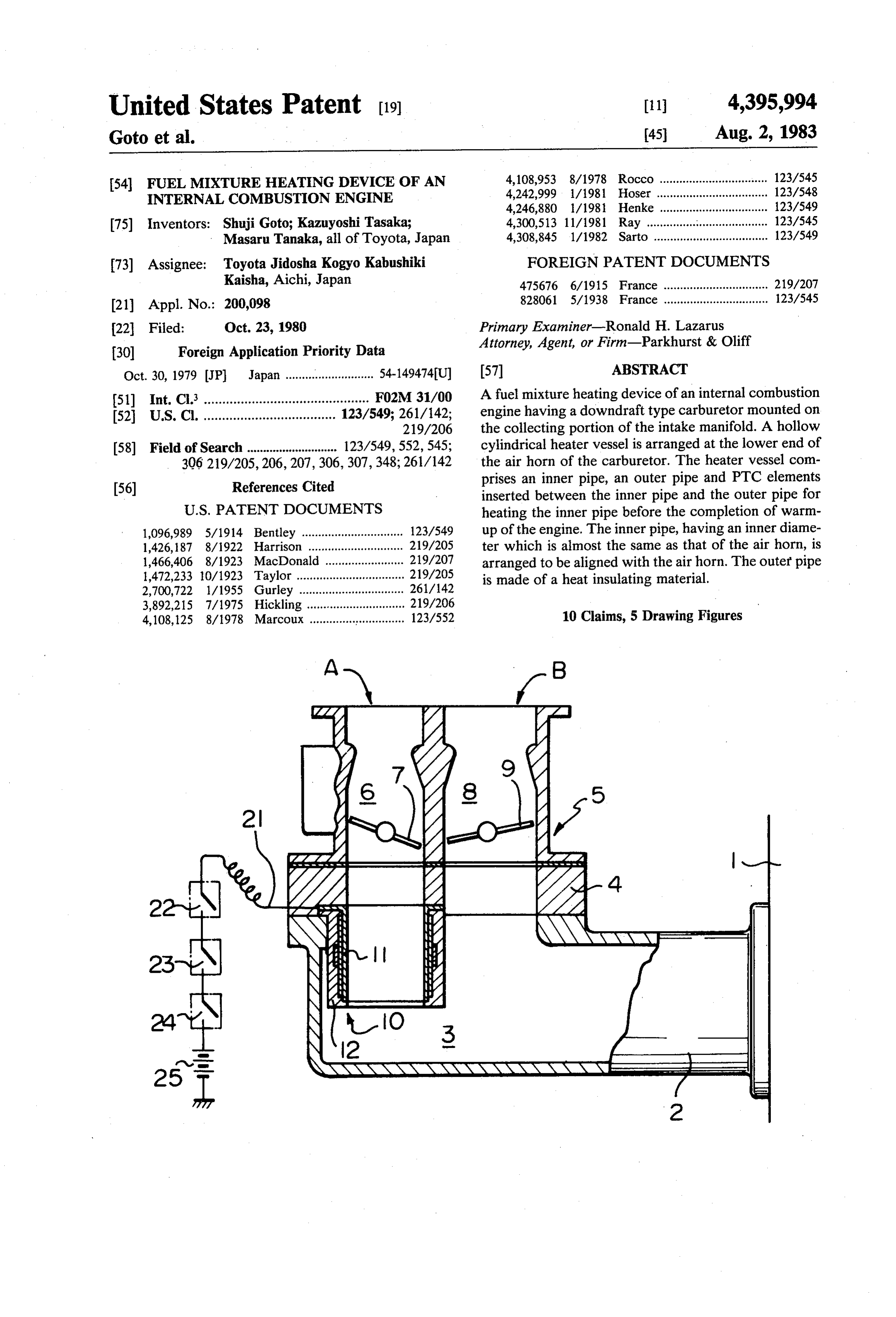
CO components in the exhaust gas can be reduced and, FIG. 1 is a cross-sectional side view of an intake also, specific fuel consumption can be improved. In 35 system of an engine, illustrating an embodiment of a fuel order to promote the vaporization of the fuel before the mixture heating device according to the present inven completion of warm-up of the engine, a fuel vaporiza tion;
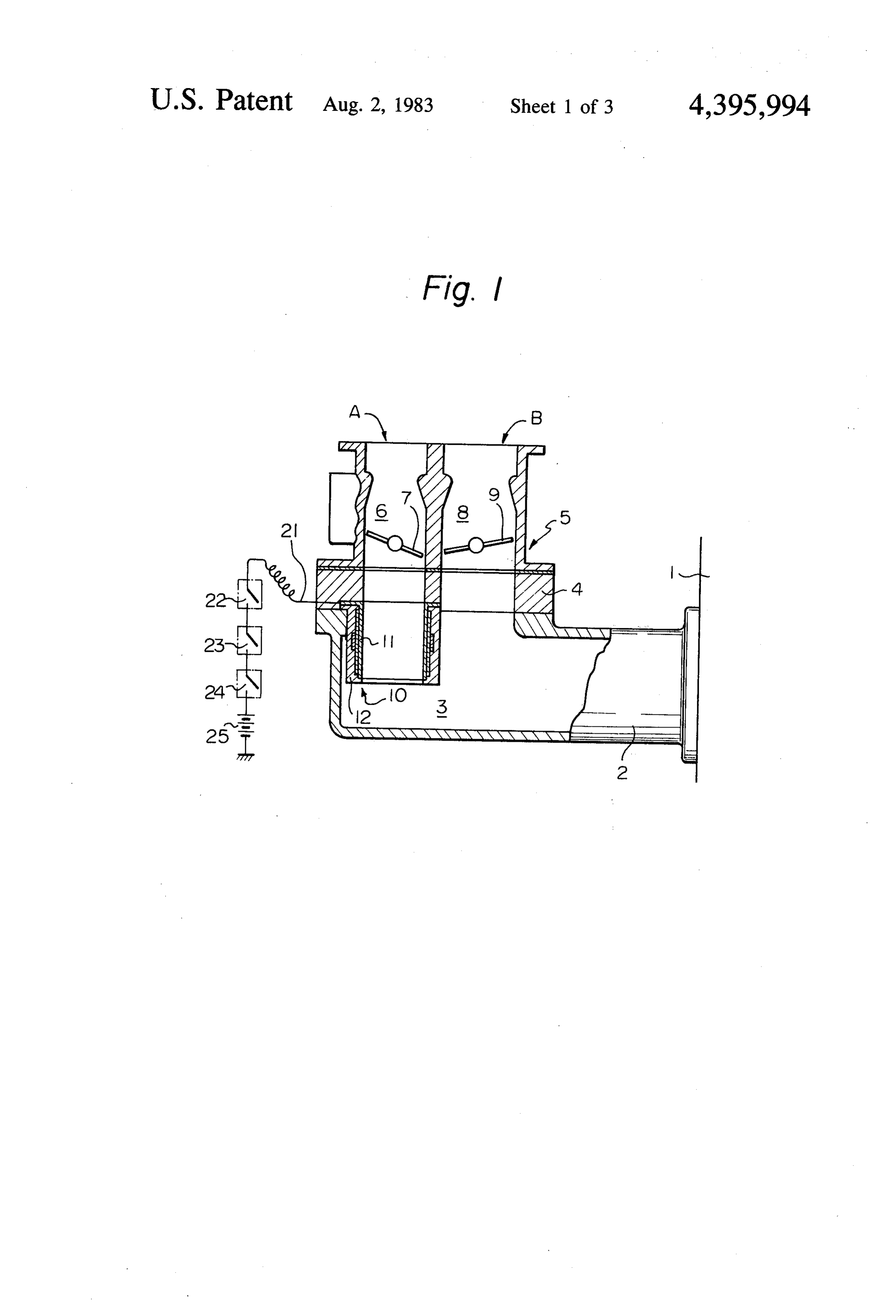
tion promoting device has been known, in which the FIG. 2 is an enlarged cross-sectional view of a por riser portion of the intake manifold is heated by the tion of the intake system illustrated in FIG. 1, taken exhaust gas which is introduced to the riser portion along the line II-II in FIG. 3;
from the exhaust system of the engine. However, in FIG. 3 is a corss-sectional view taken along the line such a conventional fuel vaporization promoting de III-III in FIG. 2;
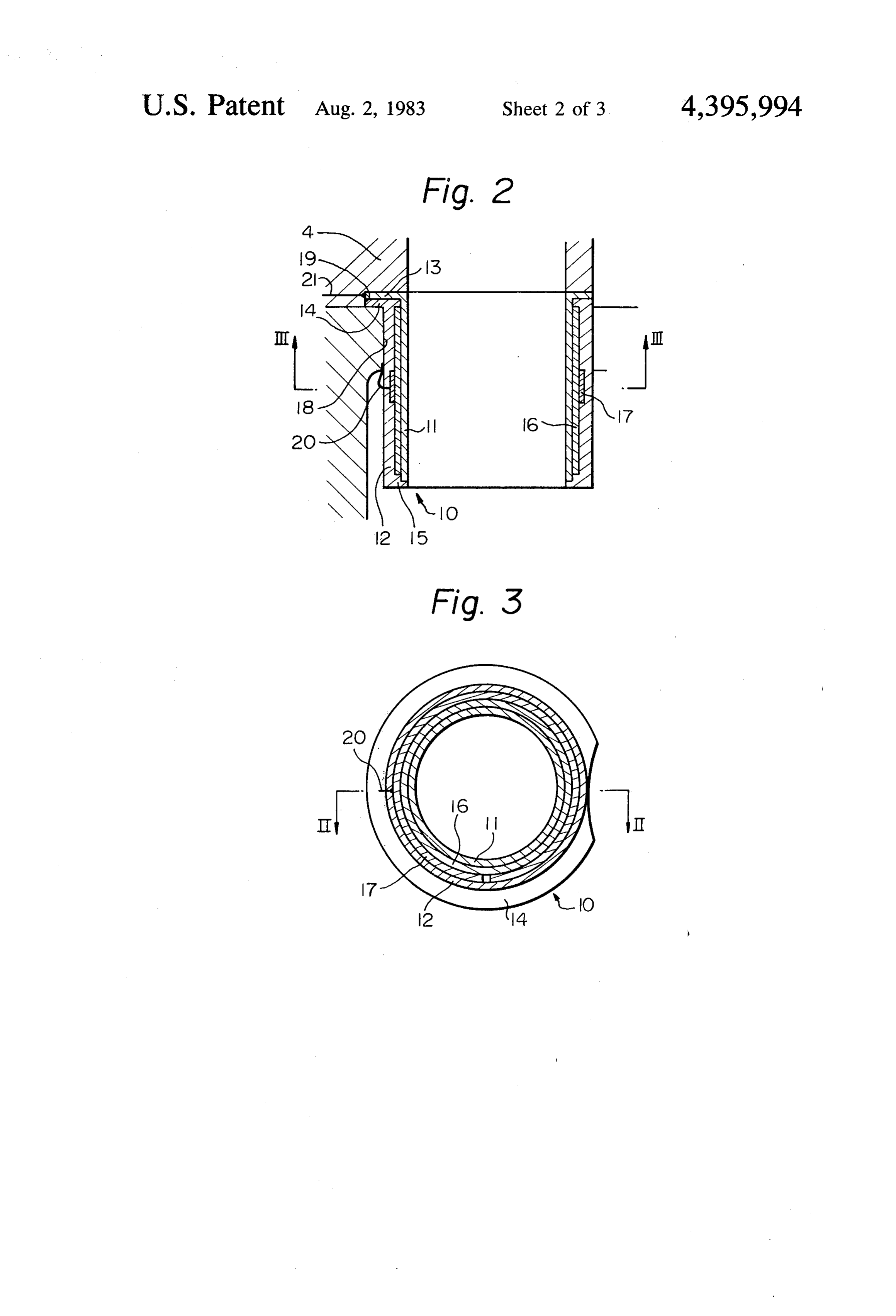
vice, in which the heat of the exhaust gas is used for FIG. 4 is a cross-sectional side view of another em promoting the vaporization of the fuel, there is a disad bodiment according to the present invention, taken vantage in that it is difficult to promote the vaporization 45 along the line IV-IV in FIG. 5, and; of the fuel immediately after the engine is started, be FIG. 5 is a cross-sectional view taken along the line cause the temperature of the exhaust gas is not instanta V-V in FIG. 4.
neously increased after the engine is started. In order to DESCRIPTION OF PREFERRED eliminate the above disadvantage, a fuel vaporization EMBODIMENTS promoting device has been proposed, in which a Posi 50 tive Temperature Coefficient Thermister element (here Referring to FIG. 1, 1 designates an engine body, 2 an inafter referred to as a PTC element) having a homey intake manifold, 3 a collecting portion of the intake comb construction is inserted between the intake mani manifold 2, and 4 a heat insulating plate; 5 designates a fold and the carburetor for heating the entire mixture carburetor fixed onto the intake manifold 2 via the heat flowing into the intake manifold from the carburetor. 55 insulating plate 4. The carburetor 5 comprises a primary However, a large part of the mixture fed from the car carburetor A having a vertically extending primary air buretor flows on the inner wall of the air horn of the horn 6 and a primary throttle valve 7, and a secondary carburetor in the form of liquid fuel and, therefore, in carburetor B having a vertically extending secondary order to promote the vaporization of the fuel fed from air horn 8 and a secondary throttle valve 9. As illus the carburetor, it is necessary to concentrically heat the trated in FIGS. 1 and 2, a hollow cylindrical heater liquid fuel flowing along the inner wall of the air horn vessel 10, having an inner diameter which is almost the of the carburetor. Nevertheless, in this fuel vaporization same as that of the primary air horn 6, is arranged in the promoting device, only a small part of the heat issued heat insulating plate 4 located beneath the primary car from the PTC element is used for heating the liquid fuel, buretor A so that the lower portion of the heater vessel while the remaining large part of the heat issued from 65 10 projects into the collecting portion 3 of the intake the PTC element is used for heating air. Consequently, manifold 2. As illustrated in FIGS. 2 and 3, the heater in this fuel vaporization promoting device, a satisfac vessel 10 comprises an inner pipe 11 and an outer pipe tory vaporization of the liquid fuel cannot be obtained 12. The inner pipe 11 has a thin wall and is made of a
Page 6
material, such as an aluminum alloy, having a high current is started, as mentioned above, the temperature thermal conductivity. The outer pipe 12 has a relatively of the PTC element 16 is instantaneously increased and, thick wall and is made of a heat insulating material. The as a result, the temperature of the inner pipe 1 is instan inner pipe 11 has on its upper end a horizontally out taneously increased.
wardly extending upper flange 13 formed in one piece When the engine is started, a large part of the fuel fed thereon, and the outer pipe 12 has on its upper end a from the primary carburetor A flows downward on the horizontally outwardly extending upper flange 14 inner wall of the primary air horn 6 in the form of liquid formed in one piece thereon. In addition, the outer pipe fuel and then flows downward on the inner wall of the 12 has on its lower end a horizontally inwardly extend inner pipe 11 of the heater vessel 0. Consequently, the ing lower flange 15 formed in one piece thereon. A O liquid fuel, flowing downward on the inner wall of the cylindrical PTC element 16, having a thin wall, is in inner pipe 11, is heated by the inner pipe i and, thus, serted between the inner pipe 11 and the outer pipe 12, vaporization of the liquid fuel is promoted. As illus so that the inner wall of the PTC element 16 comes trated in FIG. 2, the PTC element 16 is surrounded by firmly into contact with the outer wall of the inner pipe the outer pipe 15 made of a heat insulating material. 11. Consequently, the inner wall of the PTC element 16 15 Therefore, only an extremely small part of the heat is electrically connected to the inner pipe 11. In addi issued from the PTC element 16 escapes to the intake tion, a resilient ring 17 is connected onto the outer wall manifold 2. Consequently, a large part of the heat issued of the PTC element 16 and, thus, the outer wall of the from the PTC element 16 is used for heating the inner PTC element 16 is electrically connected to the resilient pipe 11. In addition, the inner wall of the inner pipe 11 ring 17. The heater vessel 10 illustrated in FIG. 2 is 20 is covered by the liquid fuel and, thus, a large part of the formed in such a way that, after the PTC element 16 is heat issued from the PTC element 16 is used for promot fitted onto the inner pipe 16, the resilient ring 17 is fitted ing the vaporization of the liquid fuel. onto the PTC element 16 and, then, a synthetic resin When the temperature of the cooling water of the layer, forming the outer pipe 12, is formed around the engine exceeds 60° C. a little while after the engine is outer wall of the PTC element 16. 25 started, the temperature reactive switch 22 is turned to As illustrated in FIG. 2, the intake manifold 2 has a the OFF position and, as a result, the supply of the hole 18 having an inner diameter which is almost the electric current fed into the PTC element 16 is stopped. same as the outer diameter of the outer pipe 12, and the The PTC element 16 is made of a ceramic material heater vessel 10 is inserted into the hole 18. In addition, and can be easily shaped in the form of a hollow cylin the heat insulating plate 4 has on its lower end an in 30 drical shape having a thin wall. However, it is difficult creased diameter portion 19, arranged adjacent to the to form the PTC element 16 so that the corss-section hole 18 and the upper flanges 13 and 14 are inserted into thereof becomes precisely equal to a circle and, there the increased diameter portion 19. As illustrated in FIG. fore, there is a possibility the inner wall of the PTC 2, the resilient ring 17 is connected to the intake mani element 16 does not completely contact the outer wall fold 2 via a lead 20. In addition, one end of the lead 21 35 of the inner pipe 11. Consequently, in order to obtain is connected to the inner pipe 11 and, as illustrated in complete contact between the inner wall of the PTC FIG. 1, the other end of the lead 21 is connected to a element 16 and the outer wall of the inner pipe 11, it is power source 25 via a temperature reactive switch 22, a preferable that the PTC element 16 be divided into voltage reactive switch 23 and an ignition switch 24. more than two pieces. FIGS. 4 and 5 illustrate another The temperature reactive switch 22 is in the ON posi 40 embodiment in which the PTC element is divided into a tion when the temperature of the cooling water of the plurality of pieces. Referring to FIGS. 4 and 5, a plural engine is lower than, for example, 60 C., while the ity of PTC element pieces 26, each being shaped in the temperature reactive switch 22 is turned to the OFF form of a hollow cylindrical body, is inserted between position when the temperature of the cooling water of the inner pipe 11 and the outer pipe 12, and the PTC the engine exceeds 60° C. The voltage reactive switch 45 element pieces 26 are urged onto the outer wall of the 23 is in the OFF position when the voltage, produced at inner pipe 11 due to the resilient force of the resilient the neutral point of the alternator (not shown) driven by ring 17. By using a plurality of the PTC element pieces the engine, is lower than a predetermined level, while 26, since the contacting area between the outer wall of the voltage reaction switch 23 is turned to the ON posi the inner pipe 11 and the inner walls of the PTC element tion when the voltage, produced at the neutral point of 50 pieces 26 is increased, it is possible to improve the ther the alternator, is increased beyond the predetermined mal conductivity between the inner pipe 11 and the level. PTC element pieces 26. In addition, in this embodiment, As is known to those skilled in the art, a large amount a plurality of vertically extending fins 27 are formed in of electric current flows within the PTC element 16 one piece on the inner wall of the inner pipe 11 for when the supply of the electric current is started. Con 55 promoting the vaporization of fuel droplets floating in sequently, during the time the starter motor (not shown) the mixture and for improving the efficiency of the is operated for starting the engine, it is necessary that thermal conductivity by increasing the area of the ther the supply of the electric current not be fed into the mal conductive surface.
PTC element 16. To this end, the voltage reactive According to the present invention, since a large part switch 23 is provided. That is, when the engine is com 60 of the heat issued from the PTC element is used for pulsorily rotated by the starter motor, the voltage, pro heating liquid fuel, it is possible to fully promote the duced at the neutral point of the alternator, is very low. vaporization of the liquid fuel. Consequently, even if a On the other hand, when the engine begins to rotate fuel mixture, which is leaner than that used in a prior under its own power, the voltage, produced at the neu art, is used before the completion of warm-up of the tral point of the alternator, is increased. As a result of 65 engine, good combustion can be obtained and, thus, a this, the voltage reactive switch 23 is turned to the ON stable operation of the engine can be ensured. In addi position and, thus, an electric current begins to be fed tion, since it is possible to use such a leaner mixture into the PTC element 16. When the feed of the electric before the completion of warm-up of the engine, the
Page 7
amount of harmful components can be reduced, and 3. A fuel mixture heating device as claimed in claim 2, specific fuel consumption can be reduced. wherein said PTC element has a hollow cylindrical While the invention has been described by reference shape having a thin wall.
to specific embodiments chosen for purposes of illustra 4. A fuel mixture heating device as claimed in claim 2, tion, it should be apparent that numerous modifications wherein said PTC element comprises a plurality of could be made thereto by those skilled in the art with pieces, each being shaped in the form of a portion of a out departing from the basic concept and scope of the hollow cylindrical body. invention. 5. A fuel mixture heating device as claimed in claim 1, We claim: wherein the collecting portion of the intake manifold 1. A fuel mixture heating device of an internal com 10 has6.aAhole into which said heater vessel is inserted. bustion engine having an intake manifold and an intake wherein saidmixture fuel device heating device as claimed in claim 1, comprises a heat insulating plate passage which has an outlet connected to a collecting having a hole and is inserted portion of the intake manifold, the intake passage hav and the collecting portion ofbetween the the intake passage intake manifold, said ing a fuel feed apparatus for feeding fuel into the intake 15 heater vessel having an outwardly extending flange passage, said device comprising: portion at an inlet portion thereof, which is located a power source, and a hollow cylindrical heater vessel arranged at the opposite hole of to the outlet portion of said heater vessel, the said heat insulating plate having an increased outlet of the intake passage and having an outlet diameter portion into which the flange portion of said portion which projects into the collecting portion 20 heater vessel is inserted.
of the intake manifold, said heater vessel compris 7. A fuel mixture heating device as claimed in claim 1, ing a hollow cylindrical inner pipe, a hollow cylin wherein said inner pipe has an end face at said outlet drical outer pipe made of a heat insulating material, portion, and said outer pipe has at said outlet portion an and a heater element connected to said power inwardly extending flange which is in engagement with source, said heater element being between said 25 the end face of said inner pipe.
inner pipe and said outer pipe and directly contact 8. A fuel mixture heating device as claimed in claim 1, ing both said inner pipe and said outer pipe, said wherein said heat vessel has a plurality of axially ex inner pipe being aligned with the intake passage tending fins formed in one piece thereon. and having a uniform inner diameter throughout its 9. A fuel mixture heating device as claimed in claim 1, length which is substantially the same as that of the 30 wherein said device further comprises a first switch intake passage whereby the inner pipe transmits which is in the ON position when the temperature of heat to the fuel mixture in order to vaporize it and the engine is lower than a predetermined temperature, acts as an electrode, while the outer pipe acts as a and a second switch which is in the ON position when heat insulator. the engine is operating under its own power, said heater 2. A fuel mixture heating device as claimed in claim 1, 35 element being connected to said power source via said wherein said heater element comprises a PTC element first switch and said second switch.
having an inner wall which is in contact with an outer 10. A fuel mixture heating device as claimed in claim wall of said inner pipe, said heater vessel further com 9, wherein said second switch is operated in response to prising a resilient ring connected onto the outer wall of a change in voltage produced at a neutral point of an said PTC element for electrically connecting the outer 40 alternator which is driven k . .
the
engine.
wall of said inner pipe to said resilient ring.
Provenance
- Collection
- Cited prior art
- Original PDF
- patentimages.storage.googleapis.com →
- Filed
- 1980-10-23
- Pages
- 7
- Method
- pdftotext (the PDF's own text layer) + pdftoppm 300dpi page scans
- Source
- Google Patents bibliographic record
- Granted
- 1983-08-02
- Inventors
- Shuji Goto; Kazuyoshi Tasaka; Masaru Tanaka; Toyota Jidosha Kogyo KK
- Transcribed from
- patentimages.storage.googleapis.com →