patent · US4147136
Fuel reforming system for an internal combustion engine
3 April 1979
Page 1 — bibliographic record
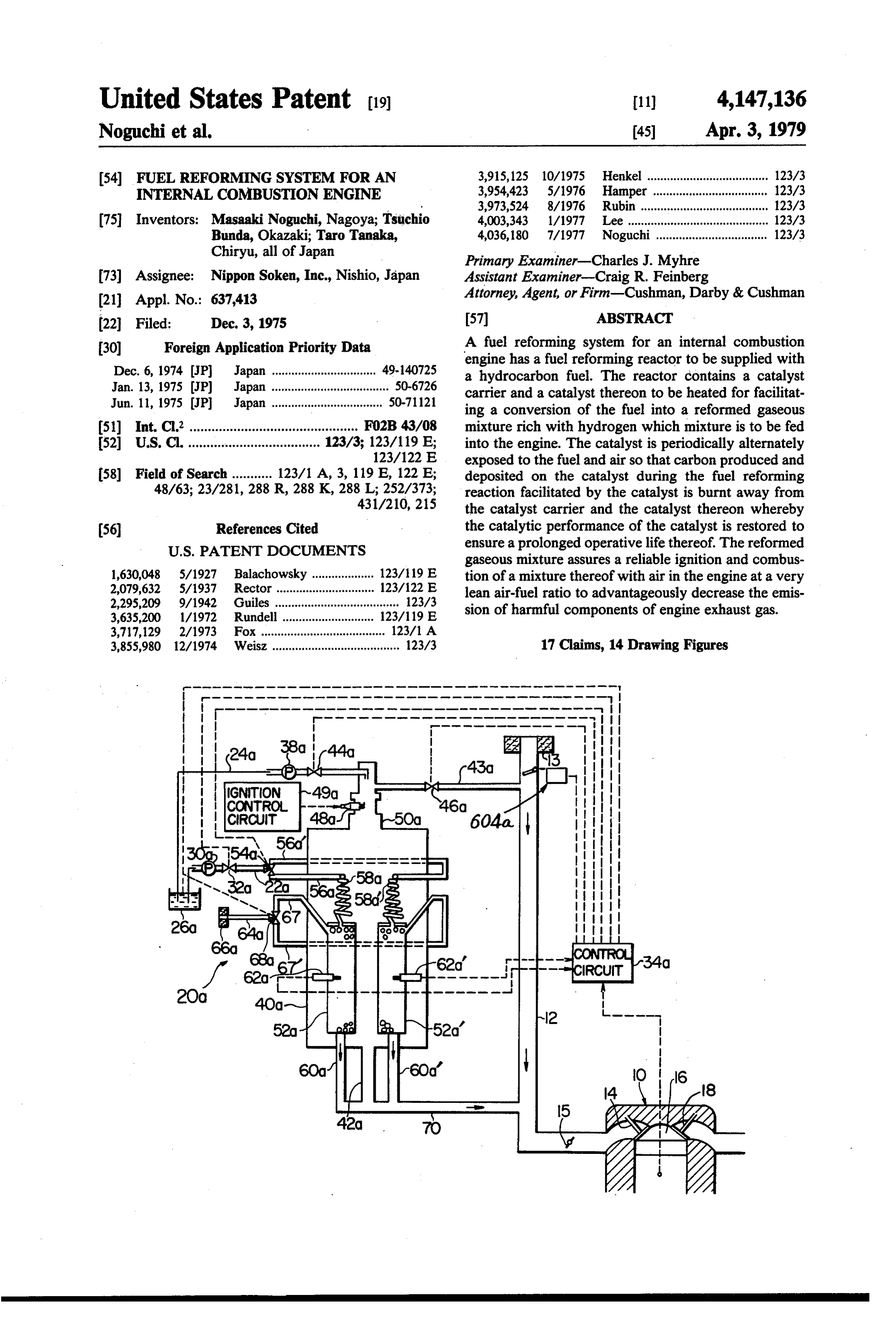
United States Patent (19) 11) 4,147,136 Noguchi et al. 45 Apr. 3, 1979 54 FUEL REFORMING SYSTEM FOR AN 3,915,125 10/1975 Henkel ..................................... 123/3 INTERNAL COMBUSTON ENGINE 3,954,423 5/1976 Hamper ................................... 123/3 3,973,524 8/1976 Rubin ....................................... 123/3 75 Inventors: Masaaki Noguchi, Nagoya; Tsuchio 4,003,343 lol977 Lee ........................................... 123/3 Bunda, Okazaki; Taro Tanaka, 4,036,180 7/1977 Noguchi.................................. 123/3 Chiryu, all of Japan Primary Examiner-Charles J. Myhre 73 Assignee: Nippon Soken, Inc., Nishio, Japan Assistant Examiner-Craig R. Feinberg (21) Appl. No.: 637,413 Attorney, Agent, or Firm-Cushman, Darby & Cushman (22 Filed: Dec. 3, 1975 57 ABSTRACT 30) Foreign Application Priority Data A fuel reforming system for an internal combustion engine has a fuel reforming reactor to be supplied with
Dec. 6, 1974 JP Japan ................................ 49-140725 a hydrocarbon fuel. The reactor contains a catalyst Jan. 13, 1975 JP Japan .................................... 50-6726 carrier and a catalyst thereon to be heated for facilitat Jun. 11, 1975 JP Japan .................................. 50-7112 ing a conversion of the fuel into a reformed gaseous 51) Int. Cl. .............................................. FO2B 43/08 mixture rich with hydrogen which mixture is to be fed 52 U.S. C. .................................... 123/3; 123/119 E; into the engine. The catalyst is periodically alternately 123/122 E exposed to the fuel and air so that carbon produced and 58) Field of Search........... 123/1 A, 3, 119 E, 122 E; deposited on the catalyst during the fuel reforming 48/63; 23/281, 288 R, 288 K, 288 L; 252/373; reaction facilitated by the catalyst is burnt away from 431/210, 215 the catalyst carrier and the catalyst thereon whereby (56) References Cited the catalytic performance of the catalyst is restored to
gaseous mixture assures a reliable ignition and combus 1,630,048 5/1927 Balachowsky ................... 123/19 E tion of a mixture thereof with air in the engine at a very 33 3. s a 4 x asa a so 8 v 8 & 8 w8 + v 89 123/ 2. lean air-fuel ratio to advantageously decrease the emis 3.63 5200 1/1972 Rundell ... 123/119 E sion of harmful components of engine exhaust gas. 3,717,129 2/1973 Fox ..... . 123/1 A 3,855,980 12/1974 Weisz ....................................... 123/3 17 Claims, 14 Drawing Figures
-- a-- - - - - - - - - - - - - - -n - a -a -a -- - - -es on as were wear- - - - - - - - - - - - - - - - - - - - - - - one- - - - - - - - - -- was rena- arosses - - -
CIRCUIT
Page 2
Drawing sheet — no readable text.
Page 3
Drawing sheet — no readable text.
Page 4
Drawing sheet — no readable text.
Page 5
Drawing sheet — no readable text.
Page 6
Drawing sheet — no readable text.
Page 7
Drawing sheet — no readable text.
Page 8
Drawing sheet — no readable text.
Page 9
Drawing sheet — no readable text.
Page 10
Drawing sheet — no readable text.
Page 11
engine and the reduction in the emission of HC, CO and
FUEL REFORMING SYSTEM FOR AN INTERNA NO.
COMBUSTON ENGINE The present invention further aims to alternately RELATED APPLICATION expose the catalyst to the fuel for the catalytic reform 5 ing reaction thereof into the reformed gaseous mixture
This application is generally related to our copending and to air for the removal of carbon produced and application of similar title, Ser. No. 596,743, filed July deposited on the catalyst during the reforming reaction 17, 1975. s so that the performance of the catalyst is restored, the BACKGROUND OF THE INVENTION deterioration of the catalyst due to the carbon deposit is O avoided and the operative life of the catalyst is pro 1. Field of the Invention longed.
The present invention relates to a fuel reforming The fuel reforming system of the present invention system for an internal combustion engine which system includes a burner for igniting and burning a mixture of has a burner for burning a part of a hydrocarbon fuel to a part of a hydrocarbon fuel to be fed into an associated produce combustion gas and a fuel reforming reactor 15 internal combustion engine and a part of air to be sup vessel to be heated by the combustion gas for convert plied to the engine to thereby produce a combustion gas ing the remainder of the fuel into a reformed gaseous of a high temperature. The combustion gas is utilized to mixture rich with hydrogen which mixture is to be fed heat a fuel reforming reaction vessel or housing and a into the engine to improve the ignitability and combus catalyst contained therein so that the vessel or housing tibility of the fuel in the engine and reduce the emission and the catalyst are heated immediately after the start of of harmful components of engine exhaust gases. the engine and so that the remainder of the fuel is con 2. Description of the Prior Art verted and reformed into a gaseous mixture of the char In order to solve the problem of pollution by exhaust acter discussed above. For the appropriate reforming gases from internal combustion engines, it has been 25 reaction, the reactor vessel or housing is preferably kept required to improve the atomization of liquid fuel and at a temperature ranging from 500' to 800° C. The cata the distribution of the fuel to respective engine cylin lyst is used to facilitate a catalytic reforming reaction so ders for improved ignition and combustion of the dis as to relieve the conditions for reaction and improve the tributed fuel. This is true with the case where a rich efficiency of the conversion. Preferably, the catalyst air-fuel mixture is supplied to a stratified charge internal 30 may comprise Nickel, Chromium, Cobalt, Iron, Rho combustion engine as well as with the case where a dium, Platinum and a combination of some of these normal air-fuel mixture is fed into a conventional inter metals.
nal combustion engine. So as to satisfy the requirement, As discussed, the reformed gaseous mixture produced there has been devised an engine in which the intake in the reactor vessel or housing contains an amount of system of the engine is heated by the engine exhaust gas 35 hydrogen. The inclusion of hydrogen in the reformed or warmed engine cooling water so that a mixture of air gaseous mixture facilitates a reliable ignition and com and a hydrocarbon fuel is heated to 80 to 150° C. Al bustion of a mixture of the reformed gaseous mixture though the fuel is atomized in the intake system, the with air and a non-reformed hydrocarbon fuel at such a system is not operative to reform or convert the fuel very large (lean) air-fuel ratio that a mixture of air and into a more easily ignitable and combustible form. Thus, a hydrocarbon fuel produced by a carburetor at the there is a problem that an engine is not smoothly opera same air-fuel ratio is by no means ignitable in an engine, ble by a mixture of air and the atomized fuel at a very whereby the emission of HC, CO and NO is greatly lean air-fuel ratio (for example, 20) and thus the supply decreased.
of such a very lean air-fuel mixture to the engine does The present invention further aims to remove a tar not advantageously result in the increase in the emission 45 component from the reformed gaseous mixture by pro of the harmful components of engine exhaust gas, i.e., viding a tar separator downstream of the fuel reforming hydrocarbon (HC), carbon monoxide (CO) and nitro reactor vessel or housing and upstream of the associated gen oxides (NO). As a fuel for an internal combustion engine. This greatly improves the distribution of the engine is generally required to be of a high octane reformed mixture to engine cylinders. The tar compo value, the fuel contains an amount of aromatic hydro 50 nent thus removed from the reformed gaseous mixture carbon (about 30 to 50% by volume) and an addition of may advantageously be used as a fuel to be burnt in the lead compound. These materials are converted by the burner to eliminate the loss otherwise caused by the engine into harmful compounds and exhausted there removal of the tar component.
from into the atmosphere to cause environmental pollu The fuel reforming system of the present invention tion. 55 eliminates the requirement for the addition of lead com SUMMARY OF THE INVENTION pound with the resultant elimination of the emission of the lead compound. Moreover, the reformed gaseous
In an attempt to solve the problems discussed above, mixture is perfectly gasified and therefore can be more the present invention aims to bring at least a part of a uniformly distributed into respective engine cylinders hydrocarbon fuel to be fed into an internal combustion compared with a merely atomized fuel to thereby elimi engine into contact with a heated catalyst to cause a nate the prior art problem of irregularlity in air-fuel decomposition or conversion of the fuel into a reformed ratio between the respective cylinders, whereby the gaseous mixture rich with hydrogen and having a low reduction in the emission of harmful components of boiling point and a high octane value so that the re engine exhaust gases is further assured. formed gaseous mixture alone or in combination with a 65 The above and other objects, features and advantages non-reformed hydrocarbon fuel can be introduced to of the invention will be made apparent by the following gether with air into an internal combustion engine for description with reference to the accompanying draw the improvement in the combustion of the fuel in the Ings.
Page 12
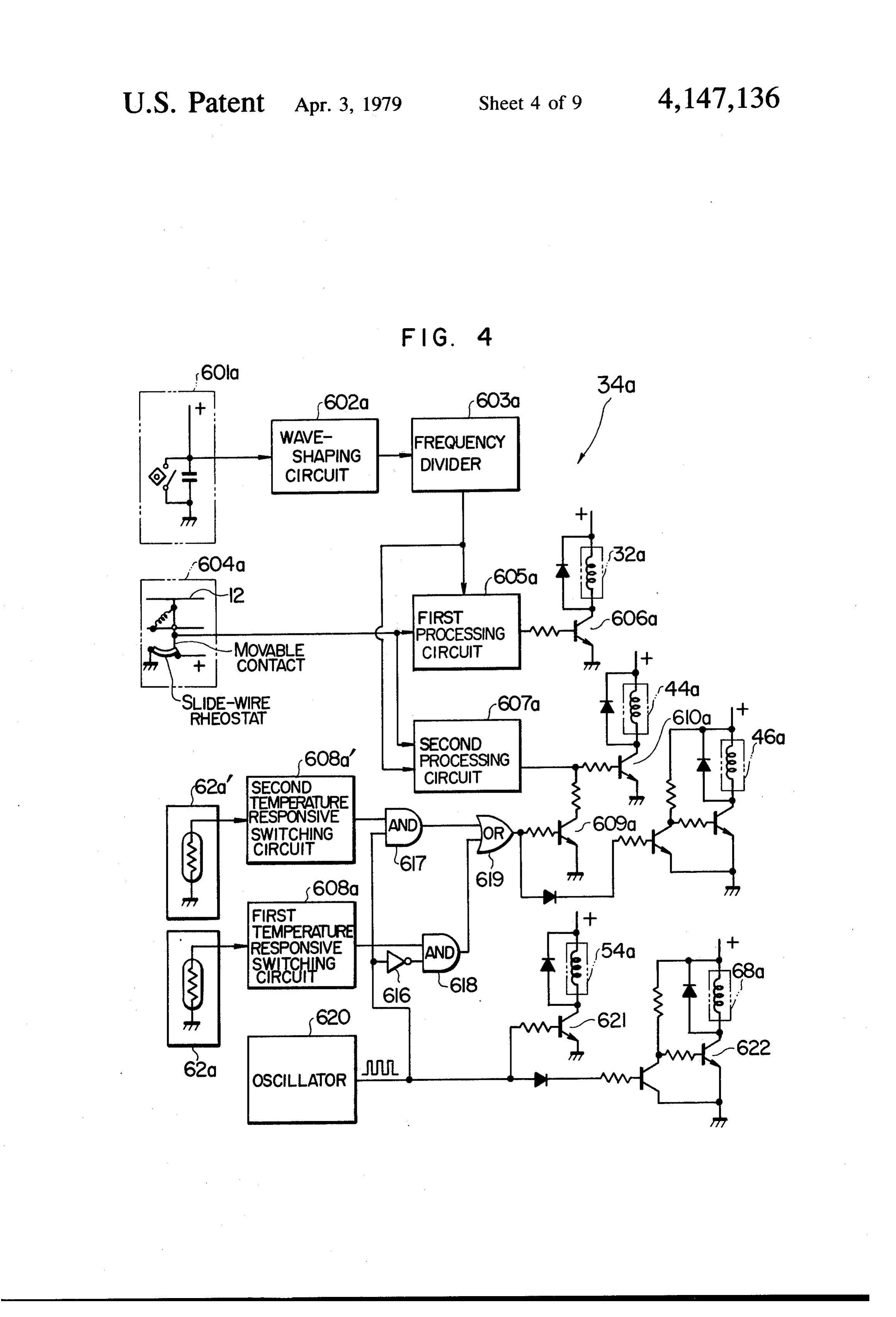
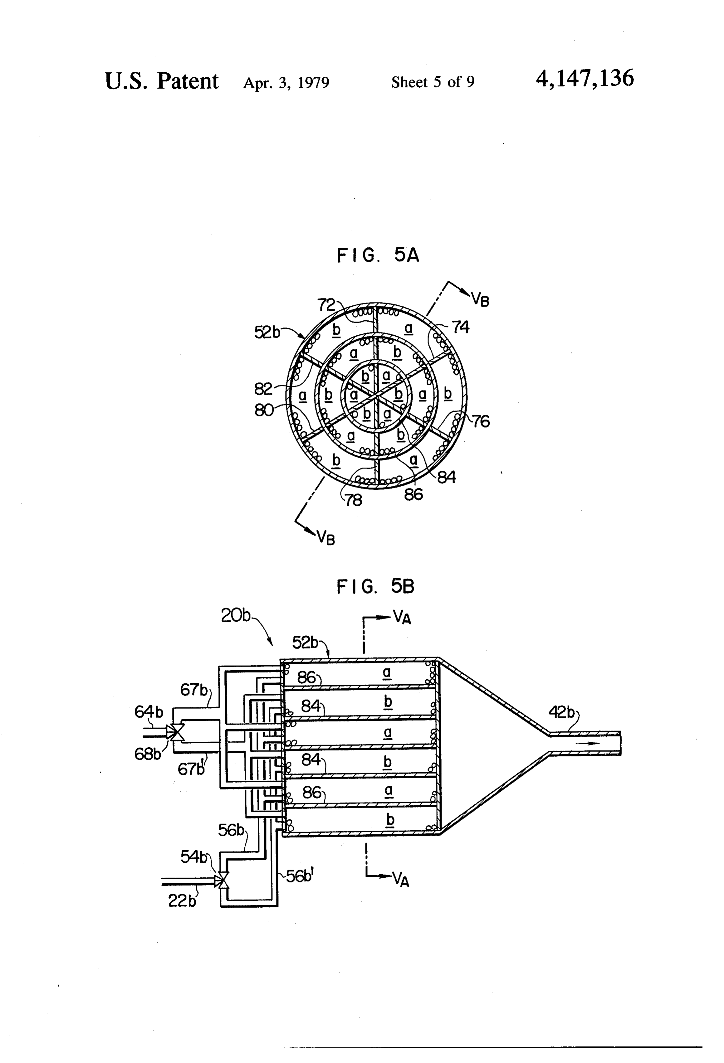
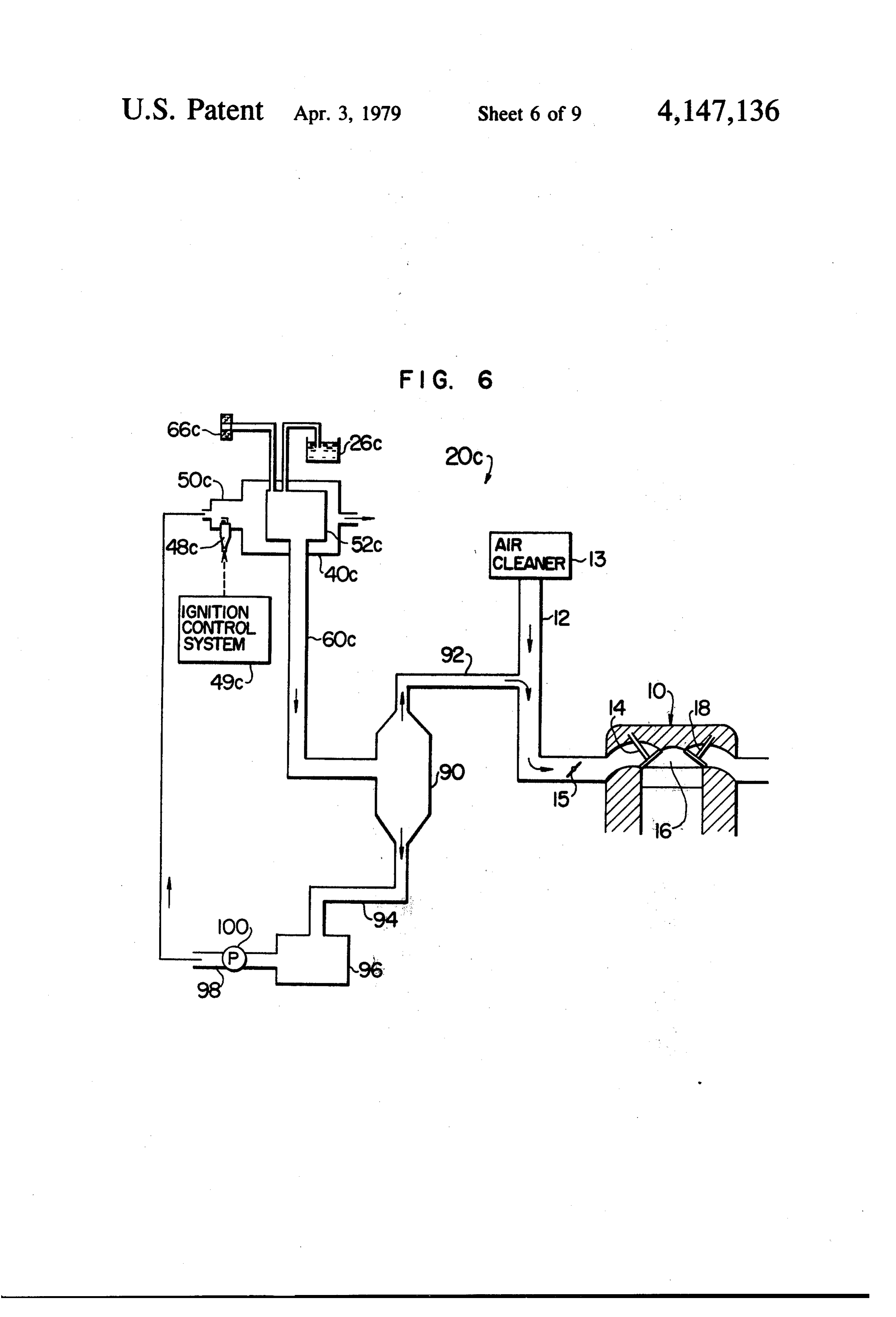
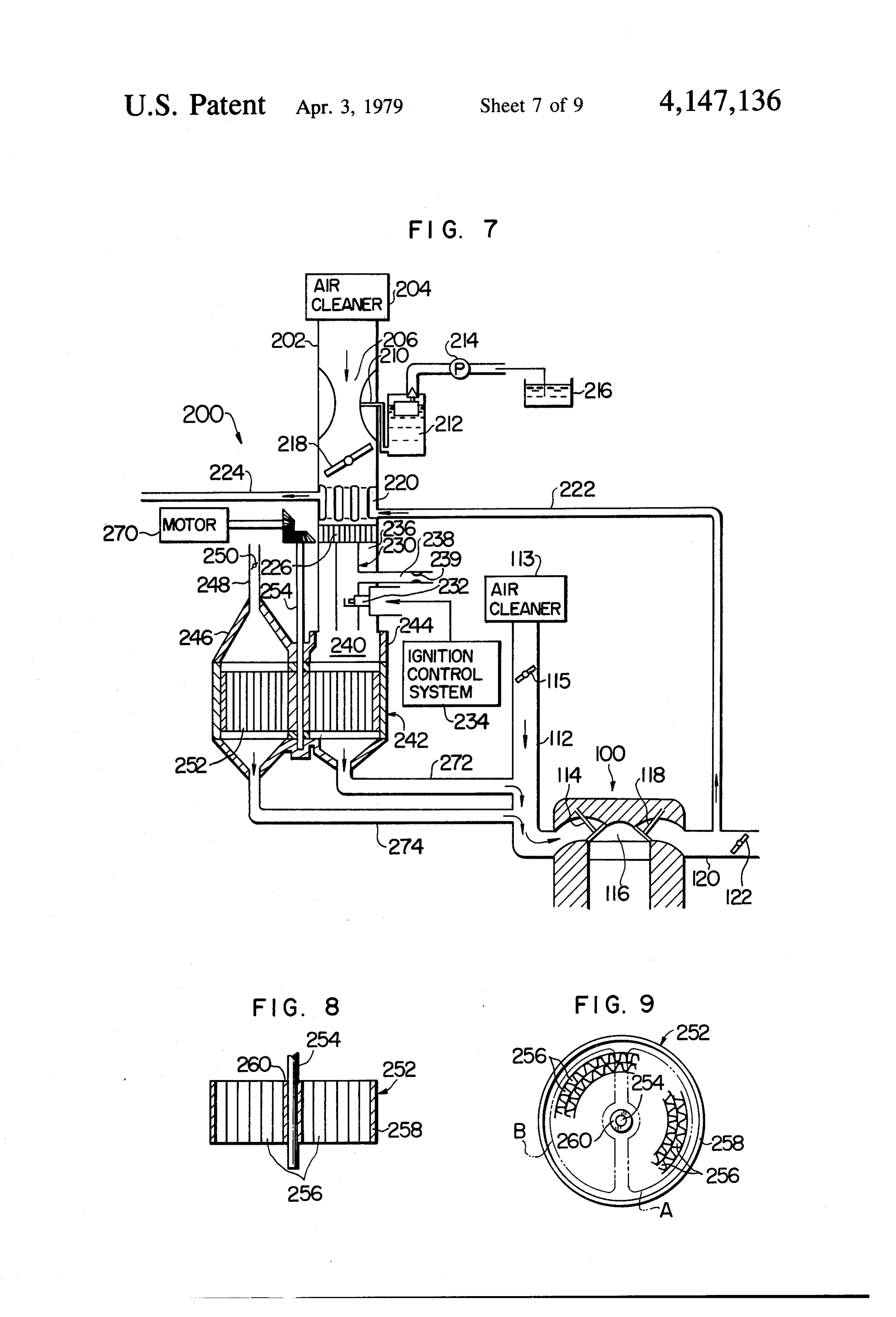
BRIEF DESCRIPTION OF DRAWINGS ing valve 46 is provided in the passage 43. The metering valves 44 and 46 are also controlled by signals from the
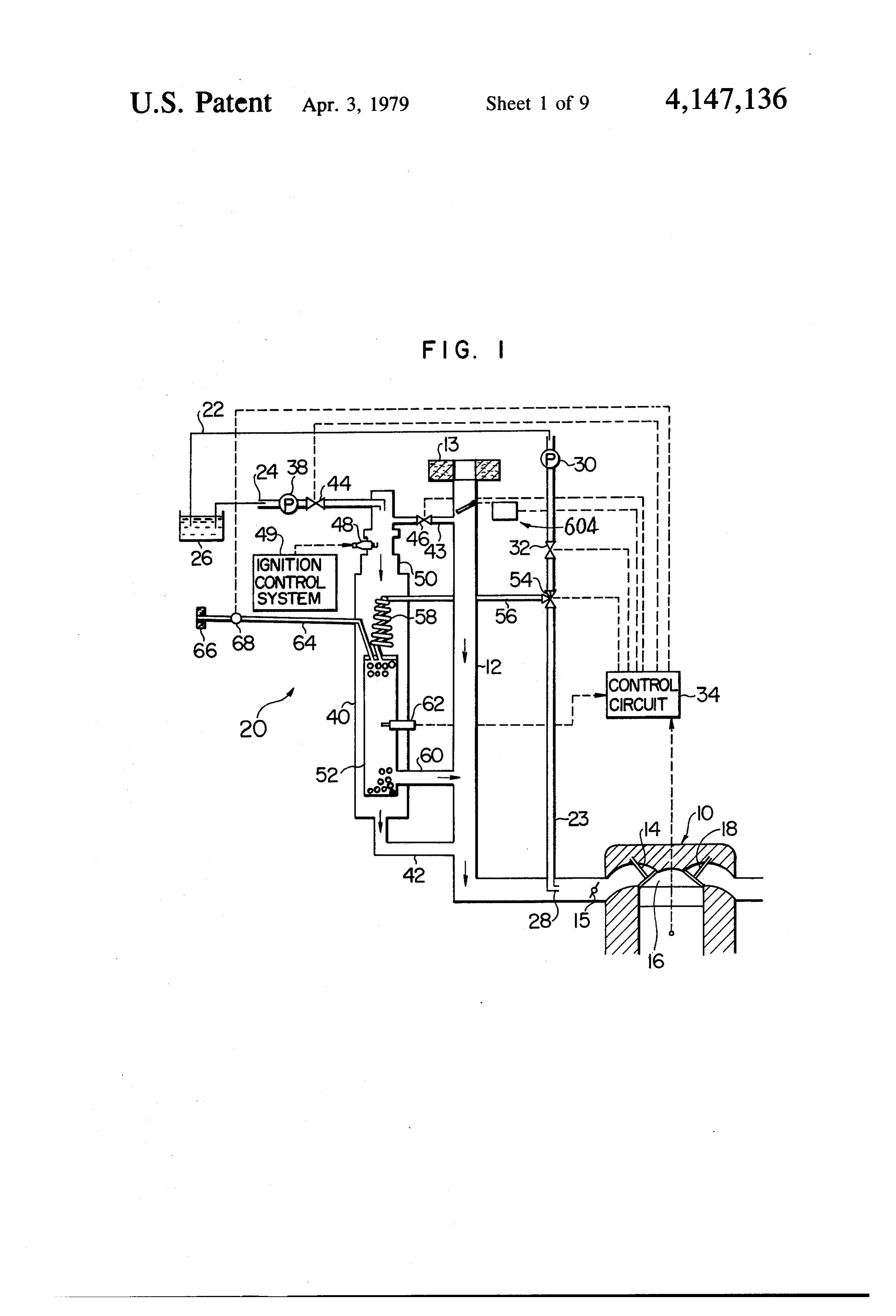
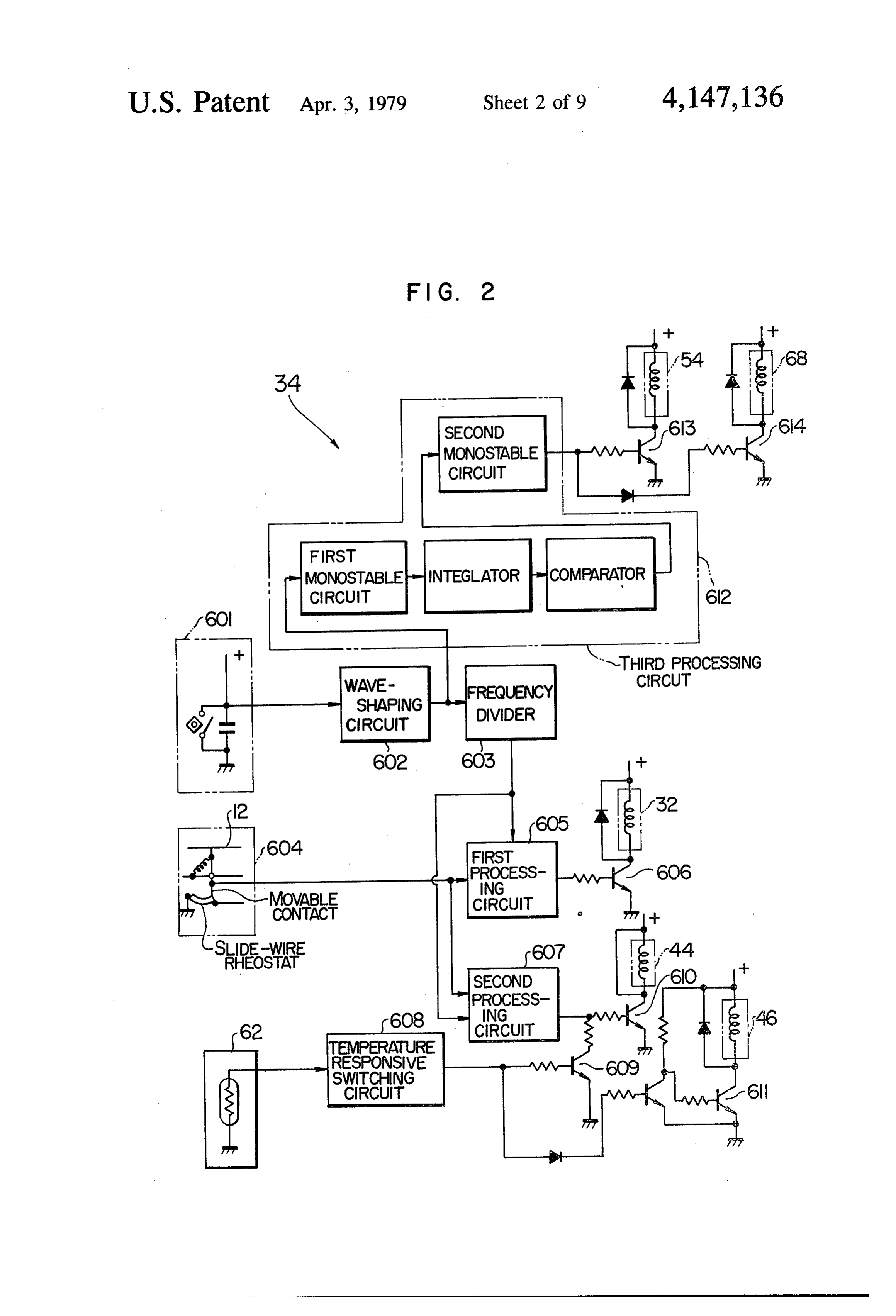
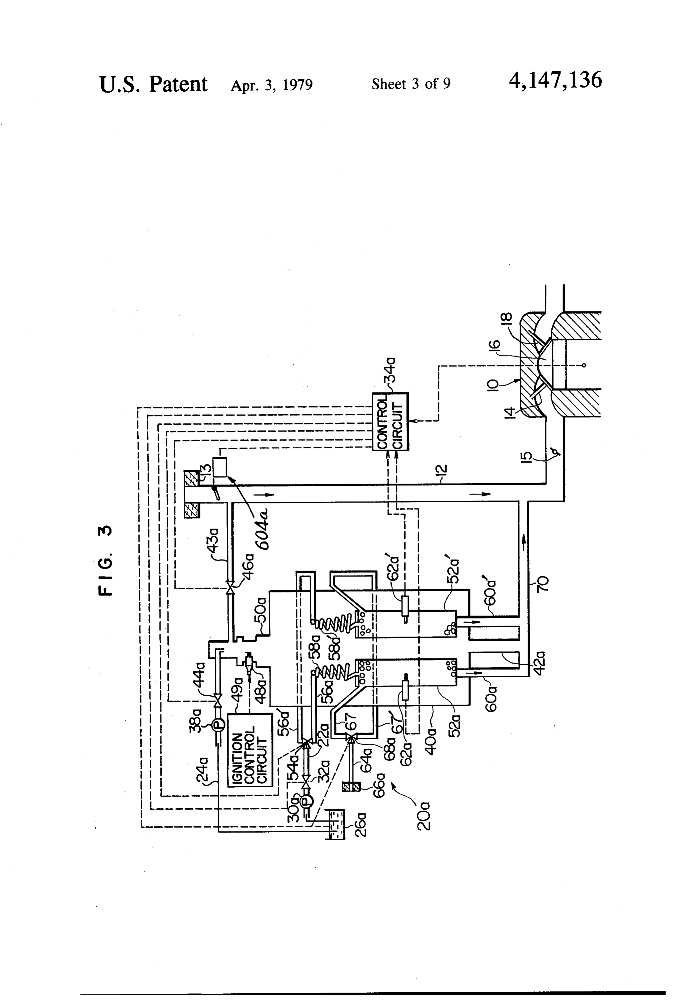
FIG. 1 is a diagrammatic illustration of a first embodi control circuit 34 so that the fuel and air are introduced ment of the fuel reforming system according to the into the enclosure and mixed therein at an air-fuel ratio present invention; appropriate for the ignition of the mixture by a spark FIG. 2 is a block diagram of a control circuit shown plug 48 mounted on the enclosure 40 and protruding in FIG. 1; thereinto adjacent to but downstream of the fuel supply FIG. 3 is a diagrammatic illustration of a second line 24 and the air passage 43. The appropriate air-fuel embodiment of the invention; ratio is preferably of a range from about 5 to about 15 in FIG. 4 is a block diagram of a control circuit shown 10 the case when the hydrocarbon fuel is gasoline. The in FIG. 3; spark plug 48 is electrically connected to a conventional FIG. 5A is a cross-section of a fuel reforming reactor ignition control system 49 including a breaker and an vessel of a third embodiment of the invention taken ignition coil which are not shown. The ignition of the along line VA-VA in FIG. 5B; air-fuel mixture produces a combustion gas of a high FIG. 5B is a partially diagrammatic, axial sectional 15 temperature, which will flow downwardly toward the view of the reactor vessel shown in FIG. 5A taken other end of the enclosure 40. For this reason, the part along line VB-VB therein; 50 of the enclosure 40 adjacent to the spark plug 48 will FIG. 6 is a diagrammatic illustration of a fourth em be called "burner'.
bodiment of the invention; A fuel reforming reactor vessel 52 is housed in the FIG. 7 is a diagrammatic illustration of a fifth em 20 enclosure 40 and disposed downstream of the burner 50. bodiment of the invention; The vessel 52 is filled with catalyst particles each of a FIGS. 8 and 9 are axial and cross-sectional views of a pellet-like shape. Examples of the catalysts are Nickel, catalyst carrier shown in FIG. 7, respectively; Chromium, Cobalt, Iron, Rhodium, Platinum and a FIGS. 10 and 11 are axial and cross-sectional views of combination of some of these metals. It will be appreci a modified catalyst carrier; 25 ated that the combustion gas produced by the burner 50 FIG. 12 is a diagrammatic illustration of a sixth em flows downwardly in heat exchange relationship with bodiment of the invention; and the catalyst particles in the vessel 52 so that the particles FIG. 13 is a similar illustration of a seventh embodi are heated by the combustion gas. ment of the invention. A three-way valve 54 is provided in the first fuel 30 supply line 22 downstream of the valve 32. A conduit 23
DESCRIPTION OF PREFERRED extends from the valve 54 to a nozzle 28 disposed in the
EMBODIMENTS
intake pipe 12 of the engine 10 upstream of the throttle
Referring to FIG. 1, a first embodiment of the fuel valve 15. A conduit 56 extends from the three-way reforming system according to the present invention is valve 54 into the enclosure 40 in which the conduit 56 generally designated by 20 and designed to be used with 35 is connected to one end of a spiral conduit 58 the other an internal combustion engine generally indicated by end of which is connected to one end of the fuel reform 10. The engine 10 may be a rotary piston engine, a ing reactor vessel 52. The three-way valve 54 is also stratified charge engine or a conventional, normal type controlled by signals from the control circuit 34 so that of engine. The engine illustrated is of a type which has the flow of the fuel through the first fuel supply line 22 an intake pipe 12, an air cleaner 13 at the top of the can be changed-over to the conduit 56 or alternatively intake pipe, an intake valve 14, a combustion chamber to the conduit 23. When the fuel from the valve 54 flows 16 and an exhaust valve 18. The fuel reforming system into and through the conduit 56, the fuel flows through 20 includes a first and second fuel supply lines 22 and 24 the spiral conduit 58 in heat exchange relationship with connected at one ends to a fuel tank 26, respectively. A the combustion gas from the burner 50 so that the fuel pump 30 is provided in the fuel supply line 22 to pump 45 is heated and vaporized and introduced into the fuel a hydrocarbon fuel from the tank 26 and through the reforming reactor vessel 52 in which the fuel is brought line 22 at a predetermined constant pressure. Down into contact with the heated catalyst whereby a cata stream of the pump 30 in the first fuel supply line 22, lytic reaction takes place to convert the fuel into a gase there is provided a metering valve 32 operative to con ous mixture which is rich with hydrogen and thus is trol the flow of the fuel therethrough in accordance 50 easily ignitable by a spark plug (not shown) of the en with the operating conditions of the engine 10. The gine. The reactor vessel 52 is connected at its other end operation of the valve 32 is controlled by signals from a to the intake pipe 12 of the internal combustion engine control circuit 34 which is designed to receive from a 10 by a passage 60so that the reformed gaseous mixture conventional sensor (not shown) signals representing is fed into the intake pipe 12 upstream of the throttle operating conditions of the engine. The sensor may 55 valve 15 of the engine 10.
conveniently detect the degree of opening of a throttle A temperature sensor 62 is mounted on the reactor valve 15 of the engine 10, the rotational speed of the vessel 52 and electrically connected to the control cir engine or the rate of air flow into the engine. The con cuit 34 for the purpose to be made apparent later. trol circuit 34 will be described later. A second air supply line 64 extends from an air The second fuel supply line 24 interconnects the fuel cleaner 66 and is connected to the one end of the fuel tank 26 and one end of an elongated enclosure 40 which reforming reactor vessel 52, the first air supply line in turn is connected at its other end to the intake pipe 12 being the passage 43. A solenoid-operated shutoff valve of the engine by a passage 42. The enclosure 40 is also 68 is provided in the second air supply line 64 and is connected by a passage 43 to the intake pipe 12. The electrically connected to the control circuit 34. The second fuel supply line 24 includes a pump 38 similar in 65 valve 68 is controlled such that air from the air cleaner operation to the pump 30 in the first fuel supply line 22. 66 flows through the valve 68 into the reactor vessel 52 A fuel metering valve 44 is provided in the fuel supply when the three-way valve 54 is changed-over to direct line 24 downstream of the pump 38, while an air meter the fuel from the first fuel supply line 22 through the
Page 13
conduit 23 to the nozzle 28 and directly into the intake circuit 612. A further power transistor 614 is also opera pipe 12, i.e., when the fuel from the first fuel supply line tive in response to signals from the third processing 22 bypasses the fuel reforming reactor vessel 52. circuit 612 to control the valve 68 in the second air Referring to FIG. 2, the control circuit 34 shown in supply line 64.
FIG. 1 includes a reference signal generator 601 gener With the above-described construction and arrange ating reference signals in synchronism with the rotation ment of the fuel reforming system 20, when the engine of the engine 10. In the illustrated embodiment of the 10 is operated, the control circuit 34 receives signals invention, the generator 601 is in the form of a contact which represent the operating condition of the engine breaker. The signals generated by the generator 601 are to vary the ratio of the period of time while the meter received and shaped by a waveshaping circuit 602. A 10 ing valve 32 is open relative to the period of time while frequency divider 603 divides the frequency of the out the valve is closed for thereby controlling the flow of put signals from the waveshaping circuit 602. the hydrocarbon fuel pumped from the fuel tank 26 to An air-flow meter 604 is mounted on the intake pipe the fuel reforming reactor vessel 52 through the 12 of the engine 10 to detect the flow of air into the change-over valve 54. The control circuit 34 is also engine. The air-flow meter 604 may be any conven 15 operative to control the fuel and air metering valves 44 tional air-flow meter such as one employed in an elec and 46 so that the fuel and air are supplied to the burner tro-controlled fuel injection system for an internal com 50 at a controlled ratio. A mixture of the fuel and air is bustion engine. A first processing circuit 605 receives ignited by the spark plug 48 and burnt in the burner to the output signals from the frequency divider 603 and produce a combustion gas of a high temperature. The from the air-flow meter 604 to calculate the opening 20 ignition by the spark plug is controlled by the ignition and closing timing for the valve 32 which controls the control circuit 49. The combustion gas thus produced flow of fuel to be introduced into the reforming reactor flows in the enclosure 40 toward the reactor vessel 52 in vessel 52. The processing circuit 605 emits pulsated heat exchange relationship with the fuel flowing control signals in response to which a power transistor through the spiral conduit 58 in the enclosure 40 so that 606 is operative to open and close the valve 32. 25 the fuel from the first fuel supply line 22 is heated to a A second processing circuit 607 also receives output temperature high enough to vaporize the fuel during the signals from the frequency divider 603 and the air-flow passage thereof through the spiral conduit 58. The at meter 604 to calculate the opening and closing timing omized fuel is introduced into the fuel reforming reac for the valve 44 which controls the flow of fuel to be fed tor vessel 52. At this time, the valve 68 is closed by the into the burner 50. A temperature responsive switching 30 control circuit 34 so that no air flows from the air circuit 608 is operative in response to signals from the cleaner 66 into the vessel 52. The catalyst in the vessel temperature sensor 62 mounted on the reforming reac 52 is also heated by the combustion gas from the burner tor vessel 52 to generate "H" and "L' level signals, the 50 so that the catalyst is kept active to facilitate a cata "H" level signals being generated when the signals from lytic reforming reaction of the atomized fuel, so that the the temperature sensor 62 represent that the tempera 35 fuel is converted into a reformed gaseous mixture which ture in the reforming reactor vessel is higher than a can effectively be ignited and burnt in the engine 10. predetermined temperature while the "L' level signals As the rate of flow of the fuel to the fuel reforming are generated when the signals from the temperature reactor vessel 52 is continuously varied by the metering sensor 62 represent that the temperature in the vessel 52 valve 32 in accordance with the varying operating con is lower than the predetermined level. A transistor 609 ditions of the engine 10, the temperature in the reactor is operative to interrupt the transmission of the output vessel 52 is advantageously controlled. For this pur signals from the second processing circuit 607 to a pose, the control circuit 34 receives signals from the power transistor 610 when the transistor 609 receives a temperature sensor 62 mounted on the reactor vessel 52. "H" level signal from the temperature responsive The temperature responsive switching circuit 608 and switching circuit 608. The power transistor 610 is oper 45 the transistors 609, 610 and 611 of the control circuit 34 ative in response to signals from the second processing are operative to control the metering valves 44 and 46 circuit 607 to control the valve 44 when the transistor so that the fuel and air are fed to the burner 50 at rates 609 is in its "OFF' state. A transistor 611 is rendered required for the combustion therein. In other words, the nonconductive by the "H" level signal from the temper temperature in the fuel reforming reactor vessel 52 is ature responsive switching circuit 608 to close the valve 50 controlled by virtue of the rate of the combustion in the 46 in the passage 43. burner. Thus, the fuel from the first fuel supply line 22 A third processing circuit 612 is operative in response is converted into the reformed, effectively combustible to the signals from the waveshaping circuit 602 to actu gaseous mixture which is then discharged from the ate the valves 54 and 68 and comprises a first monosta reactor vessel 52 through the passage 60 into the intake ble circuit, an integrating circuit for performing D-A 55 pipe 12 of the engine and is mixed with the air from the conversion of signals from the first monostable circuit, air cleaner 13 to form an air-fuel mixture at an appropri a comparing circuit operative to decide as to whether or ate air-fuel ratio which in turn is fed into the combustion not the engine speed is higher than a predetermined chamber 16 in the engine 10.
speed thereby for emitting "H" and “L” level signals The catalyst in the vessel 52 is heated by the combus when the engine speed is higher and lower than the tion gas from the burner 50 to a temperature ranging predetermined speed, respectively, and a second mono normally from 500' to 800° C. to reform the fuel from stable circuit operative to decide the length of a "H" the first fuel supply line 22 into the gaseous mixture level signal from the comparing circuit. which is rich with hydrogen. Namely, the fuel is dis A power transistor 613 is operatie in response to solved to produce hydrogen. At this time, the carbon signals from the third processing circuit 612 to control 65 content in the fuel is educed and deposited on the sur the valve 54 so that the first fuel supply line 22 is com face of the catalyst. It has been found that the deposition municated with the conduit 23 when the transistor 613 of carbon is increased as the system is operated, so that receives a "H" level signal from the third processing the performance of the catalyst is decreased. In the
Page 14
illustrated embodiment of the invention, therefore, the ranged in parallel relationship with each other. The supply of fuel into the fuel reforming reactor vessel 52 reactor vessels 52a and 52a' are designed to be alter is stopped at a time when the engine does not produce nately brought into fuel reforming operation so that a large amount of nitrogen oxides, such as during idle when one of the vessels (52a) is supplied with fuel for operation of the engine. Thus, the fuel from the first fuel the conversion thereof into a reformed gaseous mixture supply line 22 is caused to flow through the fuel conduit rich with hydrogen, the other vessel (52a") is supplied 23 and injected from the nozzle 28 into the intake pipe with air for the removal of a carbon deposited on the 12 of the engine. At this time, the reactor vessel 52 is catalyst during the preceding fuel reforming operation supplied with air to produce a combustion reaction of the vessel 52a', and vice versa. In other words, the between the air and the carbon deposited on the cata O operation of each of the reactor vessels 52a and 52a' is lyst. More specifically, when the engine 10 is operated periodically changed into fuel reforming operation and at a low speed at which the engine does not produce a carbon removing operation so that the fuel reforning large amount of NOx, such as in idle operation of the system 20a continuously produces a reformed gaseous engine, the control circuit 34 causes the change-over mixture to be supplied into an internal combustion en valve 54 to communicate the first fuel supply line 22 15 gine 10. The construction and operation of each of the with the fuel conduit 23 for a period of time from the reactor vessels 52a and 52a are substantially similar to time the speed of the engine 10 becomes lower than a those of the reactor vessel 52 of the first embodiment. predetermined speed. At the same time, the control Thus, any further description in this concern will not be circuit 34 operates to open the valve 68 to supply air required.
from the air cleaner into the reactor vessel 52. At the 20 The enclosure 4.0a is substantially similar in construc same time, the catalyst in the vessel 52 is at a high tem tion and operation to the enclosure 40 of the first em perature such as 800° C. because the catalyst is heated bodiment with the exception that the enclosure 4.0a is by the combustion gas from the burner 50. Thus, the somewhat larger than the enclosure 40so as to accomo carbon deposited on the catalyst is oxidized by the air date the two vessels 52a and 52a' therein. A burner 50a supplied into the vessel 52 to produce carbon monoxide 25 is positioned at the upstream end of the enclosure 40a and carbon dioxide which are discharged from the ves and supplied with fuel and air from a second fuel supply sel 52 into the intake pipe 12 through the passage 60. line 24a and first air supply line 43a to produce a com Thus, the carbon deposit on the catalyst is effectively bustion gas as in the first embodiment. Fuel and air removed therefrom to recover the performance of the metering valves 44a and 46a are provided in the fuel catalyst. The combustion gas discharged from the ves 30 and air lines 24a and 43a, respectively, which are con sel 52 through the passage 60 into the intake pipe 12 is trolled by a control circuit 34a, as in the first embodi mixed with the air from the air cleaner 13 and with the ment.
combustion gas from the enclosure 40 (i.e., from the A first fuel supply line 22a is provided therein with a burner 50) to form a mixture into which the fuel from fuel metering valve 32a to be controlled by the control the fuel conduit 23 is injected to form a composite mix 35 circuit 34a as in the first embodiment. The fuel supply ture which is appropriate for combustion in the engine line 22a is divided by a three-way valve 54a into two 10, branches 56a and 56a' which extend into the enclosure After the lapse of a predetermined period of time, i.e., 40a and are connected to spiral conduits 58a and 58a' after the carbon deposite is completely removed from disposed in the enclosure 4.0a downstream of the burner the catalyst, the control circuit 34 actuates the change 50a. The spiral conduits are connected to the reactor over valve 54 and the shut-off valve 68 so that fuel from vessels 52a and 52a', respectively. The three-way valve the first fuel supply line 22 is introduced into the reactor 54a is controlled by the control circuit 34a so that when vessel 52 while the supply of air from the air cleaner 66 the fuel from a fuel tank 26a flows through one of the to the vessel 52 is stopped, whereby the vessel 52 re branches (56a) into the vessel 52a, no fuel is supplied sumes its fuel reforming operation. 45 through the other branch (56a') into the other vessel The reformed gaseous mixture thus obtained contains 52a' and vice versa.
a large amount of hydrogen and thus can be fed with the A second air supply line 64a is divided by a three-way air from the air cleaner 13 into the engine at a very lean valve 68a into two branches 67 and 67 which extend air-fuel ratio and stably ignited and burnt in the engine into the enclosure 4.0a and are connected to the vessels 10, whereby the emission of the three important harm 50 52a and 52a', respectively. The three-way valve 68a is ful components of the engine exhaust gas, i.e., HC, CO also controlled by the control circuit 34a so that air and NO, is greatly reduced and the operative life of the from an air cleaner 66a is supplied into one of the reac catalyst is greatly increased. It will be appreciated that tor vessels to which no fuel is being supplied from the an air-fuel mixture produced by a conventional carbure fuel supply line 22a.
tor at the same, very lean air-fuel ratio will not be stably 55 The enclosure 4.0a is connected at its downstream end ignitable and combustible in the conventional internal to a passage 42a which is connected by a passage 70 to combustion engine because the mixture is not reformed an air intake pipe 12 of the engine 10. The two fuel into a gaseous mixture rich with hydrogen. reforming reactor vessels 52a and 52a are connected to FIG. 3 illustrates a second embodiment of the inven the passage 70 by passages 60a and 60a, respectively, so tion generally designated by 20a. The parts of the sec that the reformed gaseous mixture and the combustion ond embodiment similar to those of the first embodi gas (including carbon monoxide and carbon dioxide) ment are indicated by similar reference numerals fol produced in the reactor vessels 52a and 52a' are mixed lowed by a character "a'. The difference of the second in the passage 70 with the combustion gas from the embodiment from the first embodiment will be mainly burner 50a and fed into the intake pipe 12 of the engine described hereunder. 65 10.
The fuel reforming system of the second embodiment Temperature sensors 62a and 62a' are mounted on the 20a comprises a pair of fuel reforming reactor vessels reactor vessels 52a and 52a' and electrically connected 52a and 52a' housed in a single enclosure 4.0a and ar to the control circuit 34a.
Page 15
FIG. 4 illustrates in block diagram the control circuit respectively, and arranged such that each of the cham 34a of the fuel reforming system 20a, The circuit 34a is bers of the first group "a" is adjacent to at least one of similar in part to the control circuit 34 of the first em the chambers of the second group "b'. The radial and bodiment of the invention. Similar parts are indicated cylindrical partitions 72 to 86 are made of a heat-con by similar reference numerals followed by a character ductive materialso that the chambers 'a' and "b" are in 'a'. The difference will be described hereunder. heat exchange relationship with each other. The vessel First and second temperature responsive switching 52b is housed in an enclosure (not shown) which may be circuits 608a and 608a' are similar in construction and similar to the enclosure 40 of the first embodiment or to operation to the temperature responsive switching cir the enclosure 4.0a of the second embodiment, cuit 608 of the first embodiment and electrically con O Referring particularly to FIG. 5B, a fuel supply line nected to the temperature sensors 62a and 62a, respec 22b extending from a fuel tank (not shown) is divided by tively. Reference numeral 616 indicates an inverter for a three-way valve 54b into two branches 56b and 56b'. inverting signals. Reference numerals 617 and 618 des The branch 56b is further branched and connected to ignate AND gates, respectively. Reference numeral 619 the first group of chambers marked "a", whereas the indicates an OR gate. These elements constitute a con branch 56a' is further branched and connected to the trol logical circuit for controlling the valves 44a and second group of chambers marked "b". A fuel metering 46a, valve (not shown) is provided in the fuel supply line 22b An oscillator 620 comprises a conventional astable upstream of the three-way valve 54b as in the second multivibrator. Power transistors 621 and 622 are opera embodiment. The not-shown valve and the valve 54b tive in response to signals from the oscillator 620 to 20 may be controlled by a control circuit (not shown) control the three-way valves 54a and 68a. which may be similar to the control circuit 34a of the The three-way valves 54a and 68a are thus controlled second embodiment.
in accordance with signals generated by the oscillator An air supply line 64b from an air cleaner (not shown) 620 so that the fuel and air supply lines to the reactor is divided by a three-way valve 68b into two branches vessels 52a and 52a' are rapidly changed-over at prede 25 67b and 67b'. The branch 67b is further branched and termined time intervals. When both reactor vessels 52a connected to the first group of chambers marked "a", and 52a' are at a temperature lower than a predeter whereas the other branch 67b' is further branched and mined temperature, the first and second temperature connected to the second group of chambers marked responsive switching circuits 608a and 608a' generate "b'. An air metering valve (not shown) is provided in “L' level signals with the result that the AND gates 617 the air supply line 64b upstream of the three-way valve and 618 emit "L' level output signals. Consequently, 68b as in the second embodiment. The not-shown valve the OR gate 619 also emits an "L' level output signal, and the three-way valve 68b may be controlled by the so that a transistor 609a is rendered non-conductive. not-shown control circuit as in the second embodiment. Accordingly, a transistor 610a is controlled by signals In operation, the three-way valves 54b and 68b are from a second processing circuit 607a with the result 35 controlled such that when the fuel from the fuel supply that the fuel metering valve 44a is controlled by signals line 64b is supplied into one of the two groups of cham from sensors 601a and 604a. bers (for example, the group "a") for the conversion of When the fuel reforming reactor vessel 52a is in fuel the supplied fuel into a reformed gaseous mixture rich reforming operation, namely, when the AND gate 618 with hydrogen, as discussed above, the other group receives an "H" level signal from the oscillator 620 40 (“b') of chambers is supplied with the air from the air through the inventor 616, the first temperature respon supply line 22b and vice versa. The carbon deposited on sive switching circuit 608a emits an "H" level signal if the catalyst particles in said the other group of cham the temperature in the vessel 52a is extraordinarily ele bers ("b') during the preceding fuel reforming opera vated, so that the AND gate 618 emits an "H' level tion of this group of chambers is burnt by the supplied signal. Consequently, the OR gate 619 emits an "H" 45 air to produce a combustion gas of a high temperature. level signal to render the transistors 610a and 611a non The heat thus produced is transmitted to the catalyst conductive with the result that the fuel and air metering particles in said one group of chambers ("a") to effec valves 44a and 46a are both closed to stop the supply of tively heat the catalyst particles. This economically fuel and air to the burner 50a, Similarly, the supply of reduces the fuel to be burnt in a burner (not shown) so fuel and air respectively from the fuel line 24a and the 50 as to heat the vessel 52b. From the above description, it air line 43a to the burner 50a is stopped when the tem will be appreciated that the first and second groups of perature of the other fuel reforming reactor vessel 52a is chambers "a' and "b' correspond in function to the extraordinarily elevated. This feature of the invention reactor vessels 52a and 52a' of the second embodiment. prevents catalysts in the reactor vessels 52a and 52a' The reformed gaseous mixture and the combustion gas from being exposed to the extraordinarily elevated tem 55 thus produced in the reactor vessel 52b are gathered perature long time and thus deteriorated by the elevated together and discharged there from through an outlet temperature. passage 42b into an intake pipe (not shown) of an inter FIGS.5A and 5B illustrate a third embodiment of the nal combustion engine (not shown) as in the preceding invention generally designated by 20b. The embodiment embodiments.
includes a generally cylindrical fuel reforming reactor FIG. 6 illustrates a fourth embodiment of the inven vessel 52b, the interior of which is divided into a plural tion generally designated by 20c. The embodiment is ity of chambers by a plurality of radially and axially characterized by the provision of a separator disposed extending partitions 72, 74,76, 78, 80 and 82 and cylin between a fuel reforming reactor vessel and an intake drical partitions 84 and 86 disposed concentrically with pipe of an engine to separate a tar component from a respect to each other and with respect to the vessel 52b. 65 reformed gaseous mixture produced in the reactor ves Each of the chambers thus defined in the vessel 52b is sel so that the rest of the reformed gaseous mixture is filled with catalyst particles. The chambers are classi fed to the engine in completely gaseous condition, fied into first and second groups marked "a' and "b', whereby the distribution of the reformed gaseous mix
Page 16
ture to respective engine cylinders is improved and the reformed gaseous mixture for certain periods of time. emission of harmful components of the engine exhaust However, it will be apparent to those skilled in the art gas is reduced.
The fuel reforming system 20c of the embodiment that the engine may be provided with a carburetor in addition to the fuel reforming system of the invention so comprises a fuel reforming reactor vessel 52c which that the engine may be similar in construction and function to anyone a non-reformedisfuel, supplied with a composite mixture of a reformed gaseous mixture and of the fuel reforming reactor vessels of the preceding air. The hydrogen content in the composite mixture embodiments. The reactor vessel 52c is housed in an may enclosure 40c having a burner 50c disposed upstream of the engine. be varied with the different operating conditions of the reactor vessel 52c. A spark plug 48c is mounted on 10 FIG. 7 illustrates a fifth embodiment of the fuel re the burner 50c and energized by an ignition control forming system of the invention generally designated by circuit 49c. as in the preceding embodiments. The reac 200 and designed tor vessel 52c is designed to be supplied with fuel and air engine 100 whichtoincludesbe used with an internal combustion an air intake pipe 112, an air from a fuel tank 26c and air cleaner 66c. Fuel and air metering valves (not shown) may be provided in the 15 combustion chamber 116, an114, cleaner 113, an intake valve a throttle valve 115, a exhaust valve 118 and an fuel and air supply lines, respectively, and controlled by exhaust a control circuit (not shown) as in the preceding em providedpipe 120. A flap valve 122 may preferably be in the exhaust pipe 120 to restrict the flow of bodiments.
The reactor vessel 52c is connected to the tar separa engine The exhaust gas therethrough.
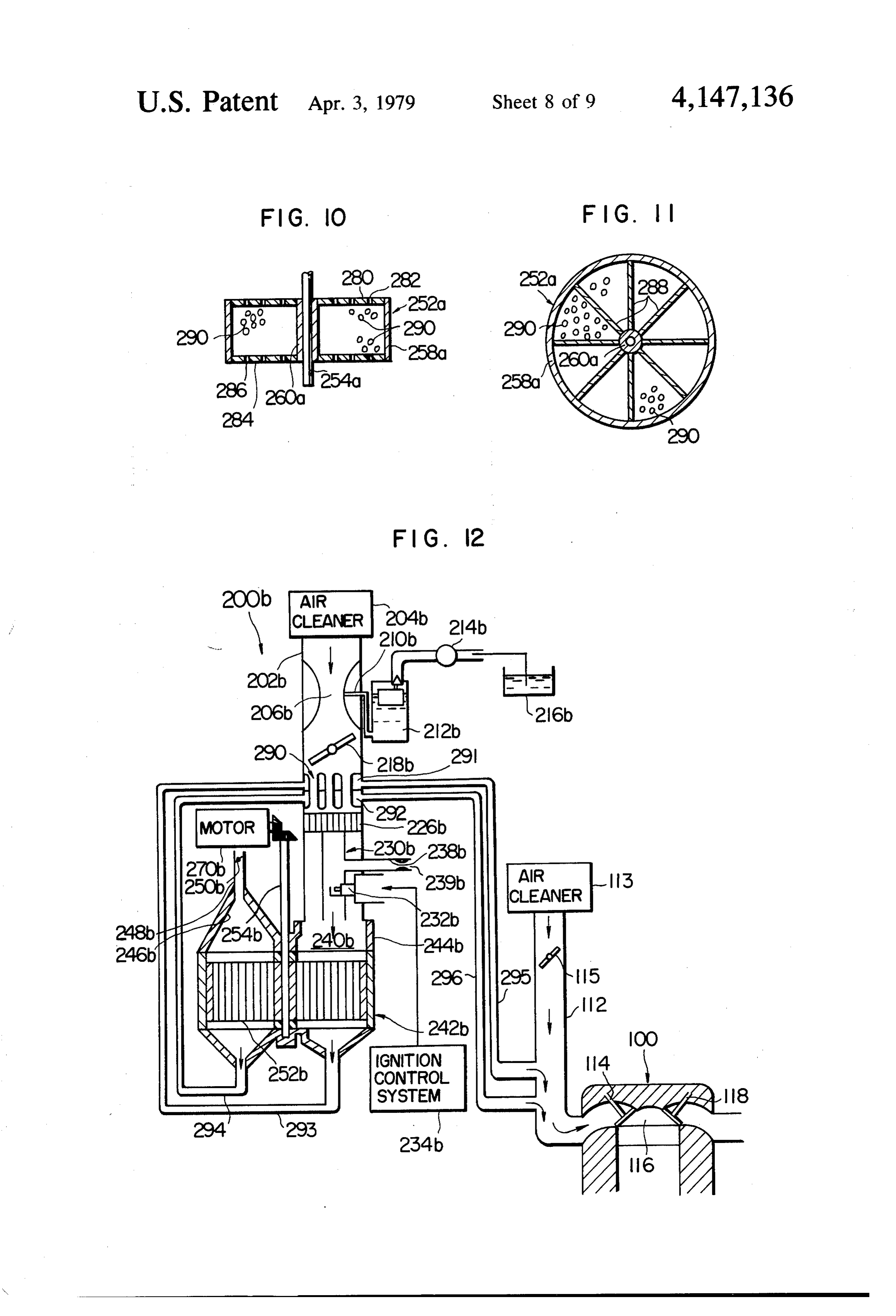
fuel reforming system 200 includes an intake tube tor 90 having an upper end connected to the intake pipe 20 12 of the engine 10 by a passage 92. The lower end of 204. 202 connected at its upstream end with an air cleaner the separator 90 is connected by a passage 94 to a reser The intake tube 202 is formed therein with venturi voir 96 which in turn is connected to the burner 50c by 206 through which air from the cleaner 204 flows and a return passage 98. A pump 100 is provided in the into which hydrocarbon fuel is jetted by a nozzle 210 so return passage 98. 25 that a rich air-fuel mixture is produced. The nozzle 210 In operation, the fuel reforming reactor vessel 52c extends from a float chamber 212 to which the fuel is produces a reformed gaseous mixture rich with hydro supplied by a pump 214 from a fuel tank 216. A throttle gen, as in the preceding embodiments. The mixture thus valve 218 is provided in the intake tube 202 downstream produced is discharged at a relatively high temperature of the venturi. 206 to control the flow of an air-fuel from the vessel 52c and introduced into the separator 90 30 mixture produced in the venturi 206. in which the relatively heavy tar component of the A heat exchanger 220 is disposed in the intake tube mixture is separated and flows downwards into the downstream of the throttle valve 218 and defines passage and thus into the reservoir 96, while the rest of therein two groups of passages, one of which groups the reformed gaseous mixture is sucked into the engine comprises a plurality of axial passages through which 10 through the passage 92 and the intake pipe 12. The 35 the air-fuel mixture flows. The other group comprises tar component is pumped by the pump 100 from the substantially transverse passages connected to one end reservoir 96 to the burner 50c and burnt therein to pro of a pipeline 222 which is connected at the other end to duce heat. Thus, the separation of the tar component the exhaust pipe 120 of the engine 100 upstream of the does not cause any energy loss. Of course, the burner flap valve 122. Because the valve 122 restricts the flow 50c may be supplied with an additional fuel through a of the engine exhaust gas through the exhaust pipe 120, fuel supply line (not shown) if the combustion of the tar a part of the engine exhaust gas flows through the pipe component in the burner does not produce sufficient line 222 and through the heat exchanger 220 into an heat to activate a catalyst in the reactor vessel 52c. outlet pipe 224 so that the air-fuel mixture flowing In the embodiment described, the combustion gases through the heat exchanger 220 is heated. The outlet produced in the burner are all introduced into engine. 45 pipe 224 may be connected to the exhaust pipe 120 of However, the burner may be operated in such a manner the engine downstream of the flap valve 122. that excess oxygen is supplied to the fuel so that a com A tubular burner 230 is disposed substantially con bustion gas comprises carbon dioxide and water. The centrically in the intake tube 202 downstream of the combustion gas or a part thereof may be introduced into heat exchanger 220 and provided with a spark plug 232 an exhaust pipe of the engine. 50 protruding into the burner and adapted to produce In the second and third embodiments, the combustion spark discharge. A conventional ignition control system gases produced by the combustion of the carbon depos 234 is electrically connected to the spark plug 232. The its are introduced into associated engines together with burner 230 has a diameter smaller than that of the intake reformed gaseous mixtures. However, the carbon de tube 202 so that only a part of the rich air-fuel mixture posits may be supplied with excess oxygen to produce 55 from the heat exchanger 220 is introduced into the carbon dioxide which can be introduced into the ex burner 230 and the remainder of the air-fuel mixture haust pipes of the engines. flows through an annular passage 236 defined between In the described and illustrated embodiments of the the inner and outer peripheral surfaces of the intake invention, the fuel reforming reactor vessels are sup tube 202 and of the burner 230. A secondary air supply plied with a hydrocarbon fuel only. However, either a 60 pipe 238 having an air-flow restricter 239 therein is rich mixture of a hydrocarbon fuel and air or a mixture connected to the burner 230 to supply secondary air at of a hydrocarbon fuel and a combustion gas produced in a rate controlled by the restricter. The arrangement is a burner may alternatively be fed into a fuel reforming such that the rich air-fuel mixture flowing into the reactor vessel. burner is diluted by the secondary air to an air-fuel ratio In the second and third embodiments of the inven 65 which is appriate for the mixture to be ignited by the tion, the reformed gaseous mixture is always produced spark plug 232 to thereby produce a combustion gas in and introduced into engines. In the first embodiment of the burner 230. A flame arrester made of a wire netting the invention, the engine is operated solely with the or a perforated plate of ceramic material extends across
Page 17
the intake tube 202 between the heat exchanger 220 and preferably from 10 to 20%. The rich air-fuel mixture ine ourner 230 to prevent backfire. supplied into the burner 230 is diluted to an air-fuel ratio A generally cylindrical housing 242 is disposed of about from 10 to 15 by the secondary air supplied by downstream of the bottom end of the intake tube 202 the secondary air supply pipe 238 and is ignited by the and has an open end the area of which is divided into spark plug 232 and bunt in the burner 230. two generally semi-circular sections to one of which the The unburnt rich air-fuel mixture passed through the bottom end of the intake tube 202 is connected by a annular passage 236 and the combustion gas produced generally semi-circular sealing wall 244 which defines in the burner 230 are mixed in the mixing chamber 240 therein a mixing chamber 240. The combustion gas to form the composite mixture. In a certain case, the produced by the burner 230 and the unburnt, rich air 10 hydrocarbon fuel contained in the composite mixture is fuel mixture passing through the annular passage 236 partially oxidized by a very small amount of oxygen flow into the mixing chamber 240 and are mixed to contained in the rich air-fuel mixture. The catalyst car gether therein to form a composite gaseous mixture. rier 258 is heated by the heat of the combustion gas The other generally semi-circular section is connected normally to a temperature of from 600 to 900 C. The by a second sealing wall 246 to an air inlet pipe 248 in 15 composite mixture is converted and reformed into the which a flap valve 250 is provided to control the flow of reformed gaseous mixture which contains a large air through the pipe 248. amount of hydrogen (about 5% by weight). The rate of A generally cylindrical or disc-like catalyst carrier the conversion and reformation greatly depends upon 252 is substantially snugly received in the housing 242 the kinds of catalysts, reaction temperature, the air-fuel and has an axle 254 rigidly secured to the catalyst car 20 ratio of the air-fuel mixture supplied, and so on. As an rier. The axle 254 is drivingly connected to a motor 270 example, an air-fuel mixture of an air-fuel ratio of 3 was so that the axle is rotated thereby together with the subjected to a reforming reaction at a reaction tempera catalyst carrier 252 at a speed of 1/5-10 r.p.m. ture of 800° C. and with a Ni catalyst to effectively Referring to FIGS. 8 and 9, the catalyst carrier 252 produce a reformed gaseous mixture the hydrogen con has a honeycomb structure formed of sheets of a heat 25 tent of which amounted substantially to 5% by weight. and corrosion-resistant material such as almina or mull In the illustrated embodiment of the invention, the heat ite. The honeycomb structure defines a plurality of axial exchanger 220 is preferably employed to more stably passages 256the walls of which carry a catalyst, such as atomize the fuel for thereby stably supplying a compos Ni, Cr, Co, Pt, Rh and a combination of some of these ite mixture to the heated catalyst carrier. The heat ex materials. The periphery of the honeycomb structure is 30 changer is not essential for the invention and the fuel reinforced by a circumferential frame 258, while the reforming system 200 from which the heat exchanger is central part of the structure is provided with a central removed will effectively be operative to produce a reinforcement 260 by means of which the honeycomb reformed gaseous mixture rich with hydrogen. The structure is secured to the axle 254. The characters 'A' reformed gaseous mixture thus converted from the and "B" in FIG. 9 indicate two generally semi-circular 35 composite mixture is discharged from the housing 242 regions of the catalyst carrier 252 which are exposed at through the passage 272 into the intake pipe 112 of the a moment to the composite mixture in the mixing cham engine 100.
ber 240 and to the air from the air inlet pipe 248. Circumferentially successive portions of the disc-like Referring agin to FIG. 7, the composite mixture catalyst carrier is successively exposed at about 800 C. formed in the mixing chamber 240 is introduced into the to the air from the air inlet pipe 248 so that carbon axial passages in a generally semi-circular region of the produced and deposited on the successive portions of catalyst carrier 252 and converted into a reformed gase the catalyst carrier during their travel across the mixing ous mixture by a reforming reaction due to a thermal chamber is oxidized or burnt to produce a combustion decomposition and/or steam-reformation of the com gas which is discharged from the housing 242 through posite mixture facilitated by the catalyst. The reformed 45 the passage 274 into the intake pipe 112 of the engine gaseous mixture is discharged from the housing 242 100. As such, the carbon deposite on the catalyst carrier through a passage and introduced into the intake pipe is effectively removed therefrom by virtue of the com 112 of the engine 100 at a position of the intake pipe 112 bustion reaction of the carbon and oxygen contained in downstream of the throttle valve 115. the air supplied through the air inlet pipe 248. By this As the catalyst carrier 252 is rotated by the motor 50 combustion reaction, the successive portions of the 270, the circumferentially successive parts of the cata catalyst carrier are heated and kept at an elevated tem lyst carrier are successively exposed to the air from the perature. Thus, the supply of air from the air inlet pipe air inlet pipe 248 so that carbon and soot deposited on 248 to the successive portions of the catalyst carrier by the walls of the axial passages in the catalyst carrier 252 no means adversely affects the fuel reforming reaction are burnt to produce a carbon monoxide or carbon 55 on these portions of the catalyst carrier. The reformed dioxide which is discharged from the housing 242 gaseous mixture from the passage 272 and the combus through a passage 274 into the intake pipe 112 of the tion gas from the passage 274 are mixed in the intake engine 100 at a postion of the intake pipe downstream of pipe 112 with the flow of air supplied from the air the throttle valve 115. cleaner 113 to form a composite mixture. The flap valve In operation, it is preferred that the rich air-fuel mix 60 115 is operative to control the rate of supply of air into ture produced in the venturi 206 be richer than an air the engine so that the composite mixture thus produced fuel mixture normally used in an internal combustion is of an air-fuel ratio appropriate for ignition in the engine. The air-fuel ratio of the rich air-fuel mixture is engine 100 by a spark plug (not shown). The composite most preferably 1 and preferably less than 5. The ratio mixture is ignitable and combustible even at such a very of the flow of the rich air-fuel mixture into the burner 65 large (lean) air-fuel ratio that a mixture of air and a mere 230 relative to the total flow of the rich air-fuel mixture hydrocarbon fuel (i.e., non-reformed fuel) produced by may be varied by varying the ratio of the cross-sectional a conventional carburetor at the same air-fuel ratio is by areas of the burner 230 and the annular passage 236 and no means ignitable and combustible, whereby the fuel
Page 18
reforming system 200 is operative to effectively reduce In the embodiments described, the combustion gas the emission of the three harmful components of the produced by the combustion of carbon deposited on the engine exhaust gas, i.e., HC, CO and NO. catalyst carrier is ultimately fed into an associated inter FIGS. 10 and 11 illustrate a modification of the cata nal combustion engine. However, an excess air may be lyst carrier 252 of the honeycomb structure. The modi supplied to the carbon deposite to completely convert fied catalyst carrier is generally designated by 252a the carbon into carbon dioxidide which may then be comprises a hollow cylindrical member 258a and a pair discharged through an engine exchaust pipe into the of generally disc-like end plates 280 and 284 which are atmosphere.
formed therein with small apertures or perforations 282 The burners 230 and 230b may be operated only dur and 286, respectively. An axle 254a is rigidly secured to O ing the time while the catalyst carriers 242 and 242b are the catalyst carrier 252a by means of a central reinforce heated to a predetermined temperature. After the cata ment 260a extending between the end plates 280 and lyst carriers are so heated, they may be supplied with 284. The interior of the catalyst carrier 252a is divided fuel only (i.e., not an air-fuel mixture) so that the fuel is by radial partitions 288 into a plurality of sectoral sec thermally decomposed. Soot or carbon produced dur tions each of which is filled with catalyst particles 290. 15 ing the thermal decomposition of the fuel may advanta F.G. 12 illustrates a sixth embodiment of the inven geously be burnt by oxigen contained in the air supplied tion generally indicated by 200b. The sixth embodiment from air inlet pipes 248 and 248b to produce heat which 200b are substantially similar in part to the fifth embodi can effectively be utilized to heat the catalyst carriers ment 200 shown in FIGS. 7 to 9. Similar parts of the 252 and 252b. In this case, a fuel injection system rather sixth embodiment are indicated by similar reference 20 than a carburetor is preferably used. numerals followed by a character “b'. The difference The internal combustion engine 100 associated with only will be described hereunder. Aheat exchanger unit the embodiments of the invention has been described as 290 comprises a pair of heat exchangers 291 and 292 being operated with a composite mixture of reformed disposed in an intake pipe 202b downstream of a throttle gaseous mixture from the fuel reforming system and air valve 218b. Each of the heat exchangers 291 and 292 25 from the air cleaner 113. A carburetor (not shown) may may be similar in construction to the heat exchanger 220 be provided in the intake pipe 112 of the engine 100 so of the fifth embodiment 200 but smaller than that. A that non-reformed hydrocarbon fuel is mixed with the pipeline 293 for a reformed gaeous mixture produced in composite mixture at a rate determined dependent on a housing 242b and a pipe line 294 for a combustion gas the operating conditions of the engine. also produced therein extend from the housing 242b to 30 In each of the illustrated fifth and sixth embodiments the heat exchangers 291 and 291, respectively, so that 200 and 200b of the invention, when the temperature of the reformed gaseous mixture and the combustion gas the engine exhaust gas, the reformed gaseous mixture are introduced both at high temperatures into the heat discharged from the housing 24.2b or the combustion exchanger unit 290 and flow therethrough into dis gas discharged from the housing becomes high enough charge pipe lines 295 and 296 and thus into an intake 35 to vaporize the air-fuel mixture produced in the venturi pipe 1A2 of an engine 100 so that an air-fuel mixture 206 or 206b sufficiently for the reforming reaction produced in a venturi 206b is effectively heated when it thereof in the housing 242 or 242b, the secondary air passes through the heat exchanger unit 290. supply restricter 239 or 239b may be closed to stop the Compared with the fifth embodiment of the invention combustion of a part of the air-fuel mixture in the 200, the sixth embodiment 200b will be advantageous in burner 230 or 230b with a stable and efficient fuel re that the reformed gaseous mixture and the combustion forming reaction in the housing 242 or 242b. In addition, gas produced in the housing 242b are introduced into a heater (not shown) may be provided in the air inlet the engine 100 after having been cooled in the heat pipe 248 or 248b to heat air to be supplied to successive exchanger unit 290 by the air-fuel mixture passing there portions of the catalyst carrier 252 or 252b to remove through thereby to improve the efficiency of charge 45 carbon therefrom so that the removal of the carbon is and thus the engine output. improved.
The illustrated sixth embodiment 200b comprises a The invention described above provides the follow pair of heat exchangers. This, however, is not essential ing advantages:
for the invention. The reformed gaseous mixture and (1) A part of a hydrocarbon fuel to be supplied into an the combustion gas produced in the housing 242b may 50 internal combustion engine is burnt in a burner to pro be mixed together and then introduced into a single heat duce heat by which the remainder of the fuel to be exchanger (not shown) disposed in the intake pipe 202b supplied to a fuel reforming reactor vessel or housing is downstream of the throttle valve 218b. Further alterna substantially perfectly vaporized; tively, one of the reformed gaseous mixture and the (2) The fuel reforming reactor vessel or housing con combustion gas produced in the housing 242b may be 55 tains a catalyst therein and is supplied with the remain directly fed into the intake pipe 112 of the engine while der of fuel so that the fuel is converted into a reformed the other may be introduced into such a single heat gaseous mixture rich with hydrogen;
exchanger to heat the air-fuel mixture produced in the (3) The catalyst in the fuel reforming reactor vessel or venturi 206b. In this alternative case, it is preferred that housing is periodically or alternately exposed to the the reformed gaseous mixture be supplied to the heat 60 remainder of fuel for the conversion and reformation exchanger and cooled therein. thereof into the reformed gaseous mixture and to air for It is to be noted that the heat exchanger unit 290 of the combustion reaction of the air with carbon pro the sixth embodiment is not essential for the embodi duced and deposited on the catalyst during the preced ment. A fuel reforming system without the heat ex ing fuel reforming reaction so that the carbon is burnt change unit 290 will be operative to produce a reformed 65 away from the catalyst to restore the performance of gaseous mixture because a part of the air-fuel mixture the catalyst;
produced in the venturi 206b is burnt in the burner 230b (4) A tar separator is disposed downstream of the fuel to heat the remainder of the mixture. reforming reactor vessel or housing in an embodiment
Page 19
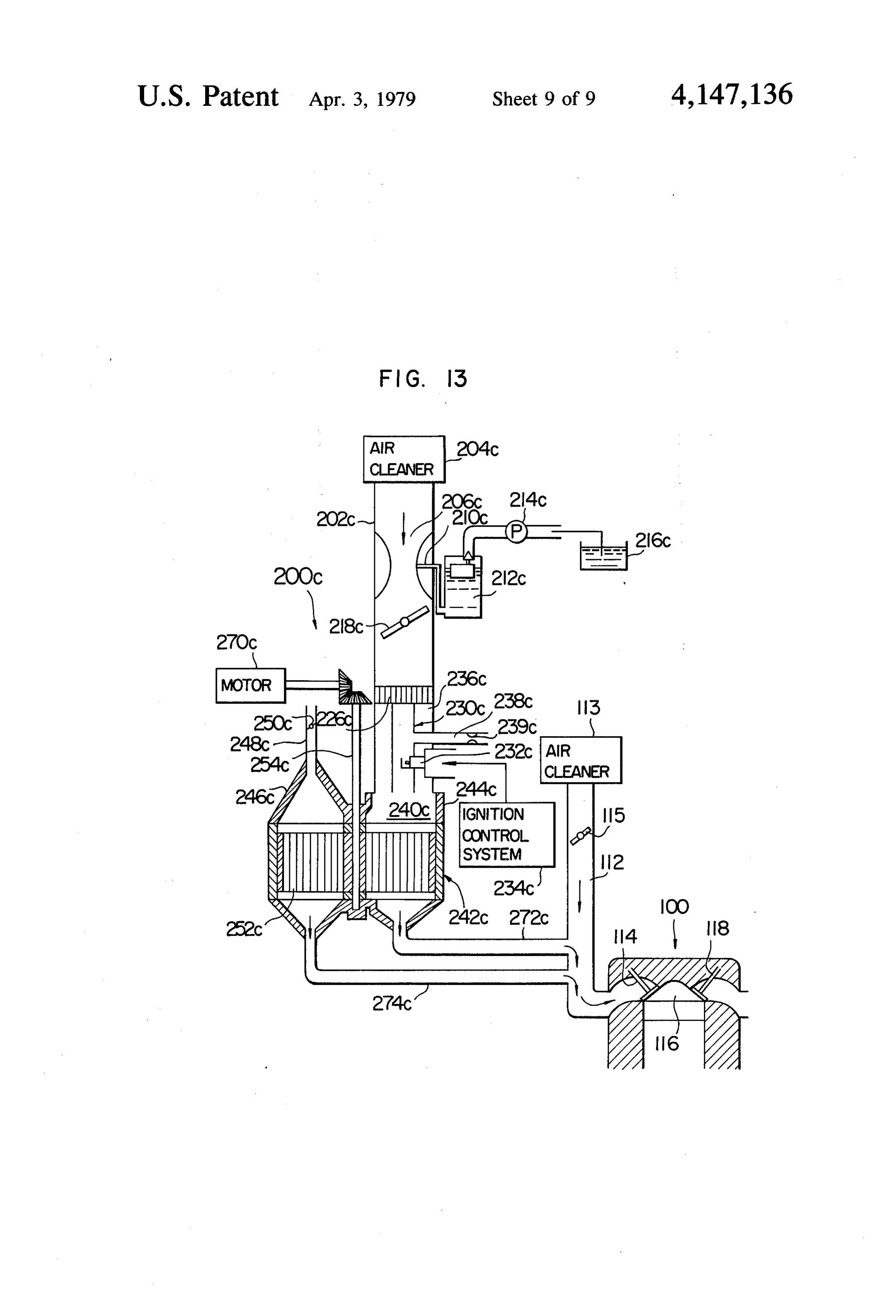
of the invention to effectively remove tar component a second air conduit operatively communicated with from the reformed gaseous mixture whereby the distri said fuel reforming reactor means through an air bution of the reformed gaseous mixture is advanta control valve for supplying air thereto; geously improved; and said control circuit also periodically actuating said air (5) The supply of the reformed gaseous mixture rich control valve to open said second air conduit dur with hydrogen to the internal combustion engine as ing a time when said second fuel conduit is closed sures the engine operation with an air-fuel mixture by said control circuit, whereby when said fuel which is of such a very large (lean) air-fuel ratio that a reforming reactor means is supplied with the air, a mixture of air and a normal fuel produced by a carbure combustion reaction is caused between the air and tor at the same air-fuel ratio is not ignitable by a spark 10 carbon produced by said reforming reaction and plug and burnt in the engine, whereby the emission of deposited on the surface of said catalyst to thereby harmful HC, CO and NOx can advantageously be re remove said carbon therefrom. duced. . 2. A fuel reforming system for an internal combustion FIG. 13 illustrates, a seventh embodiment of the in engine, which includes a combustion chamber, an air vention generally designated by 200c, The seventh em cleaner, and an intake pipe operatively communicating bodiment is substantially similar in construction and ..said air cleaner with said combustion chamber via an operation to the fifth embodiment 200 shown in FIG.7 intake valve for feeding air therethrough, comprising: with the exception that the seventh embodiment 200c a burning chamber for burning a mixture of fuel and does not have a heat exchanger for heating an air-fuel air therein to thereby produce a combustion gas of mixture before it is fed to a fuel reforming reactor. a high temperature;
Thus, it will be sufficient to make a reference that the a first air conduit operatively communicated with parts of the seventh embodiment 200c similar to the said burning chamber for supplying air thereto; corresponding parts of the fifth embodiment 200 are a fuel tank for storing a hydrocarbon fuel; indicated by similar reference numerals followed by a a first fuel conduit operatively communicating said character "c'. 25 fuel tank with said burning chamber for supplying What is claimed is: the fuel thereto;
1. A fuel reforming system for an internal combustion igniting means disposed in said burning chamber for engine, which includes a combustion chamber, an air igniting and burning the mixture of air and fuel cleaner, and an intake pipe operatively communicating respectively supplied from said first air and fuel said air cleaner with said combustion chamber via an 30 conduits;
intake valve for feeding air therethrough, comprising: a heat exchanging chamber communicated with said a burning chamber for burning a mixture of fuel and burning chamber at its upstream end and also com air therein to thereby produce a combustion gas of municated with said intake pipe at its downstream a high temperature; end for allowing said combustion gas to flow from a first air conduit operatively communicating said 35 said burning chamber to said intake pipe through intake pipe with said burning chamber for supply said heat exchanging chamber; ing air thereto from said air cleaner; first and second fuel reforming reactor vessels dis a fuel tank for storing a hydrocarbon fuel; posed in said heat exchanging chamber and each a first fuel conduit operatively communicating said having a catalyst therein for reforming a fuel into a fuel tank with said burning chamber for supplying reformed gaseous mixture including hydrogen, said the fuel thereto; first and second fuel reforming reactor vessels igniting means disposed in said burning chamber for being heated by said combustion gas flowing igniting and burning the mixture of air and fuel through said heat exchanging chamber, and said respectively supplied from said first air and fuel fuel reforming reactor vessel being communicated conduits; with said intake pipe for supplying the reformed a heat exchanging chamber communicated with said gaseous mixture to said engine; burning chamber at its upstream end and also com a second fuel conduit means alternately communicat municated with said intake pipe at its downstream ing said fuel tank with said first and second fuel end for allowing said combustion gas to flow from reforming reactor vessels, through a fuel control said burning chamber to said intake pipe through 50 valve for supplying a fuel thereto for causing the said heat exchanging chamber; catalytic reforming reaction of said fuel in said fuel fuel reforming reactor means disposed in said heat reforming reactor vessels;
exchanging chamber and having a catalyst therein a control circuit for periodically actuating said fuel for reforming a fuel into a reformed gaseous mix control valve to perform the alternate communica ture including hydrogen, said fuel reforming reac 55 tion of said fuel tank with said first and second fuel tor means being heated by said combustion gas reforming reactor vessels; and flowing through said heat exchanging chamber, a second air conduit means alternately communicated and said fuel reforming reactor means being con with said first and second fuel reforming reactor municated with said intake pipe for supplying the vessels through an air control valve for supplying reformed gaseous mixture to said engine; air thereto;
a second fuel conduit operatively communicating said control circuit actuating said air control valve in said fuel tank with said fuel reforming reactor such a manner that said second air conduit means means through a fuel control valve for supplying a supplies the air to one of said first and second fuel fuel thereto for causing the catalytic reforming reforming reactor vessels during a time when the reactor of said fuel in said fuel reforming reactor 65 supply of the fuel to said one of first and second means; fuel reforming reactor vessels from said second fuel a control circuit for periodically actuating said fuel conduit means is stopped, whereby when said one control valve to open said second fuel conduit; and of said fuel reforming reactor vessels is supplied
Page 20
with the air, a combustion reaction is caused in said 5. A fuel reforming system as claimed in claim 3, one of fuel reforming reactor vessels between the further comprising: Y air and carbon produced by said reforming reaction an air-flow meter mounted on said intake pipe for and deposited on the surface of said catalyst to detecting the flow of air supplied to said engine and thereby remove said carbon therefrom. generating an electrical signal representing said 3. A fuel reforming system for an internal combustion flow of air;
engine, which includes a combustion chamber, an air a fuel metering valve disposed in said first fuel con cleaner, and an intake pipe operatively communicating duit for closing and opening the same; and said air cleaner with said combustion chamber via an control means electrically connected to both of said intake valve for feeding air therethrough, comprising: 10 air-flow meter and fuel metering valve for actuat a burning chamber for burning a mixture of fuel and ing said fuel metering valve to close and open said air therein to thereby produce a combustion gas of first fuel conduit in response to said electrical sig a high temperature; nal, whereby the amount of the fuel supplied to said a first air conduit operatively communicated with burning chamber is controlled in response to the said burning chamber for supplying air thereto; 15 flow of air.
a fuel tank for storing a hydrocarbon fuel; 6. A fuel reforming system as claimed in claim 3, a first fuel conduit operatively communicating said further comprising:
fuel tank with said burning chamber for supplying temperature detecting means mounted on said fuel the fuel thereto; reforming reactor means for detecting the tempera igniting means disposed in said burning chamber for 20 ture thereof and producing an electrical signal igniting and burning the mixture of air and fuel representing said temperature of said fuel reform respectively supplied from said first air and fuel ing reactor means;
conduits; an air metering valve disposed in said first air conduit a heat exchanging chamber communicated with said for closing and opening the same; and burning chamber at its upstream end and also com 25 control means electrically connected to both of said municated with said intake pipe at its downstream temperature detecting means and air metering end for allowing said combustion gas to flow from valve for actuating said air metering valve to close said burning chamber to said intake pipe through said first air conduit when the temperature of said said heat exchanging chamber; fuel reforming reactor means exceeds a predeter fuel reforming reactor means disposed in said heat 30 mined value, whereby when said first air conduit is exchanging chamber and having a catalyst therein closed the supply of air to said burning chamber is for reforming a fuel into a reformed gaseous mix stopped with the result that the burning of the ture including hydrogen, said fuel reforming reac mixture in said burning chamber is prevented. tor means being heated by said combustion gas 7. A fuel reforming system as claimed in claim 3, flowing through said heat exchanging chamber, 35 further comprising;
and said fuel reforming reactor means being com an air-flow meter mounted on said intake pipe for municated with said intake pipe for supplying the detecting the flow of air supplied to said engine and reformed gaseous mixture to said engine; generating an electrical signal representing said a second fuel conduit operatively communicating flow of air; . said fuel tank with said fuel reforming reactor a fuel metering valve disposed in said second fuel means through a fuel control valve for supplying a conduit for closing and opening the same; and fuel thereto for causing the catalytic reforming control means electrically connected to both of said reaction of said fuel in said fuel reforming reactor air-flow meter and fuel metering valve for actuat means; ing said fuel metering valve to close and open said a control circuit for actuating said fuel control valve 45 second fuel conduit in response to said electrical to open said second fuel conduit; and signal, whereby the amount of the fuel supplied to a second air conduit operatively communicated with said fuel reforming reactor means is controlled in said fuel reforming reactor means through an air response to the flow of air. control valve for supplying air thereto; 8. A fuel reforming system for an internal combustion said control circuit also actuating said air control 50 engine, which includes a combustion chamber, an air valve to open said second air conduit during a time cleaner, and an intake pipe operatively communicating when said second fuel conduit is closed by said said air cleaner with said combustion chamber via an control circuit, whereby when said fuel reforming intake valve for feeding air therethrough, comprising: reactor means is supplied with the air, a combus means for producing an air-fuel mixture; tion reaction is caused between the air and carbon 55 a burning chamber disposed downstream of said mix produced by said reforming reaction and deposited ture producing means for burning the mixture to on the surface of said catalyst to thereby remove thereby produce a combustion gas of a high tem said carbon therefrom. perature;
4. A fuel reforming system as claimed in claim 5, igniting means disposed in said burning chamber for further comprising igniting and burning the mixture; a spiral fuel passage connected between said fuel a heat exchanging chamber communicated with said reforming reactor means and said second fuel con burning chamber at its upstream end and also com duit downstream of said fuel control valve for municated with said intake pipe at its downstream passing the fuel to said fuel reforming reactor end for allowing said combustion gas to flow from means therethrough, said spiral fuel passage being 65 said burning chamber to said intake pipe through disposed in said heat exchanging chamber so that said heat exchanging chamber; said passage is heated by said combustion gas to fuel reforming reactor means disposed in said heat vaporize said fuel flowing therethrough. exchanging chamber and having a catalyst therein
Page 21
for reforming a fuel into a reformed gaseous mix a heat. exchanging chamber communicated with said ture including hydrogen, said fuel reforming reac burning chamber at its upstream end and also com tor means being heated by said combustion gas municated with said intake pipe at its downstream flowing through said heat exchanging chamber, end for allowing said combustion gas to flow from and said fuel reforming reactor means being com said burning chamber to said intake pipe through municated with said intake pipe for supplying the said heat exchanging chamber; reformed gaseous mixture to said engine; first and second fuel reforming reactor vessels dis means for supplying a fuel to said fuel reforming posed in said heat exchanging chamber and each reactor means for a predetermined time period 10 having a catalyst therein for reforming a fuel into a during engine operation for causing the catalytic reformed gaseous mixture including hydrogen, said reforming reaction of said fuel in said fuel reform first and second fuel reforming reactor vessels ing reactor means; and being heated by said combustion gas flowing means for supplying air to said fuel reforming reactor through said heat exchanging chamber, and said means during other than said predetermined time fuel reforming reactor vessels being communicated period for reoccurringly causing a combustion 15 with said intake pipe for supplying the reformed reaction between the air and carbon produced by gaseous mixture to said engine; a second fuel conduit connected at one end with said said reforming reaction and deposited on the sur fuel tank for supplying the fuel therefrom; face of said catalyst for removing said carbon first and second fuel branches respectively connected therefrom. 20 at each, one end with said first and second fuel 9. A fuel reforming system as claimed in claim 8, reforming reactor vessels;
wherein said fuel supplying means comprises a passage a fuel three-way valve connected between the other disposed around said burning chamber and communi end of said second fuel conduit and the respective cating said mixture producing means with said fuel other ends of said first and second fuel branches for reforming reactor means. 25 communicating said second fuel conduit with one 10. A fuel reforming system as claimed in claim 9 of said first and second fuel branches; further comprising a control circuit periodically actuating said fuel heat exchange means disposed between said mixture three-way valve for alternately communicating producing means and said burning chamber for said second fuel conduit with said first and second causing heat exchange between an exhaust gas 30 fuel branches, to thereby alternately supply the fuel from the engine and the fuel supplied to said fuel to said first and second fuel reforming reactor ves reforming reactor means to thereby heat and va sels for causing the catalytic reforming reaction of porize said fuel passing through said fuel supplying said fuel therein;
eaS, a second air conduit for supplying air therethrough; 11. A fuel reforming system as claimed in claim 9 35 first and second air branches respectively connected further comprising at each one end with said first and second fuel heat exchange means disposed between said mixture reforming reactor vessels; and producing means and said burning chamber for an air three-way valve connected between said sec causing heat exchange between said reformed gase ond air conduit and the respective other ends of ous mixture from said fuel reforming reactor means said first and second air branches for communicat and the fuel supplied to said reactor means through ing said second air conduit with one of said first said fuel supplying means to thereby heat and va and second air branches;
porize said fuel. said control circuit also periodically actuating said air 12. A fuel reforming system as claimed in claim 9 three-way valve for alternately communicating further comprising 45 said second air conduit with said first and second means disposed downstream of said fuel supplying air branches in such a manner that said second air means and said burning chamber for mixing said conduit supplies the air to one of said first and combustion gas with the fuel from said fuel supply second fuel reforming reactor vessels through the ing means. corresponding air branch during a time when the 13. A fuel reforming system for an internal combus 50 supply of the fuel to said one of first and second tion engine, which includes a combustion chamber, an fuel reforming reactor vessels through the corre air cleaner, and an intake pipe operatively communicat sponding fuel branch from said second fuel conduit ing said air cleaner with said combustion chamber via is stopped, whereby when said one of said fuel an intake valve for feeding air therethrough, compris reforming reactor vessels is supplied with the air, a 1ng: 55 combustion reaction is caused in said one of said a burning chamber for burning a mixture of fuel and fuel reforming reactor vessels between the air and air therein to thereby produce a combustion gas of carbon produced by reforming reaction and depos a high temperature; ited on the surface of said catalyst to thereby re a first air conduit operatively communicated with move said carbon therefrom. said burning chamber for supplying air thereto; 60 14. A fuel reforming system as claimed in claim 13, a fuel tank for storing a hydrocarbon fuel; further comprising a first fuel conduit operatively communicating said first and second spiral fuel passages respectively con fuel tank with said burning chamber for supplying nected between said first and second fuel reforming the fuel thereto; reactor vessels and said first and second fuel igniting means disposed in said burning chamber for 65 branches downstream of said fuel three-way valve igniting and burning the mixture of air and fuel for passing the fuel to said fuel reforming reactor respectively supplied from said first air and fuel vessels therethrough, both of said spiral fuel pas conduits; sages being disposed in said heat exchanging cham
Page 22
ber so that said passages are heated by said combus an air metering valve disposed in said first air conduit tion gas to vaporize said fuel flowing therethrough. for closing and opening the same; and 15. A fuel reforming system as claimed in claim 13, control means electrically connected to both of said further comprising: temperature detecting means and air metering an air-flow meter mounted on said intake pipe for valve for actuating said air metering valve to close said first air conduit when the temperature of said detecting the flow of air supplied to said engine and fuel reforming reactor vessel exceeds a predeter generating an electrical signal representing said mined value, whereby when said first air conduit is flow of air; closed the supply of air to said burning chamber is a fuel metering valve disposed in said first fuel con 10 stopped with the result that the burning of the duit for closing and opening the same; and mixture in said burning chamber is prevented. 17. A fuel reforming system as claimed in claim 13, control means electrically connected to both of said further air-flow meter and fuel metering valve for actuat comprising;
ing said fuel metering valve to close and open said 15 an air-flow meter mounted on said intake pipe for detecting the flow of air supplied to said engine and first fuel conduit in response to said electrical sig generating an electrical signal representing said nal, whereby the amount of the fuel supplied to said flow of air;
burning chamber is controlled in response to the a fuel metering valve disposed in said second fuel flow of air. conduit for closing and opening the same; and 16. A fuel reforming system as claimed in claim 13, 20 control means electrically connected to both of said further comprising: air-flow meter and fuel metering valve for actuat temperature detecting means mounted on at least one ing said fuel metering valve to close and open said of said fuel reforming reactor vessels for detecting second fuel conduit in response to said electrical the temperature thereof and producing an electri- 25 signal, whereby the amount of the fuel supplied to said fuel reforming reactor vessels is controlled in cal signal representing said temperature of said fuel response to the flow of air. reforming reactor vessel;
Provenance
- Collection
- Cited prior art
- Original PDF
- patentimages.storage.googleapis.com →
- Filed
- 1975-12-03
- Pages
- 22
- Method
- pdftotext (the PDF's own text layer) + pdftoppm 300dpi page scans
- Source
- Google Patents bibliographic record
- Granted
- 1979-04-03
- Inventors
- Masaaki Noguchi; Tsuchio Bunda; Taro Tanaka; Nippon Soken Inc
- Transcribed from
- patentimages.storage.googleapis.com →