patent · US5255666
Solar electric conversion unit and system
26 October 1993
Page 1 — bibliographic record
United States Patent (19) 11 Patent Number: k
Curchod 45) Date of Patent: Oct. 26, 1993 (54) SOLAR ELECTRIC CONVERSION UNIT 56 References Cited AND SYSTEM U.S. PATENT DOCUMENTS 4,022,186 5/1977 Northrup, Jr. ...................... 126/440 76 Inventor: Donald B. Curchod, 234 Eleanor Dr., 4,069,812 1/1978 O'Neill ............................ 126/440 X Woodside, Calif., 94.062 4,307,710 12/1981 Natter ................................. 126/440
* Notice: The portion of the term of this patent 4,395,582 7/1983 Dansker ......................... 126/569 X subsequent to Nov. 28, 2007 has been 4,723,535 2/1988 Lew ................................ 126/440X disclaimed. 4,771,764 9/1988 Cluff.................................... 26/440 Primary Examiner-Larry Jones
Attorney, Agent, or Firm-Baylor G. Riddell
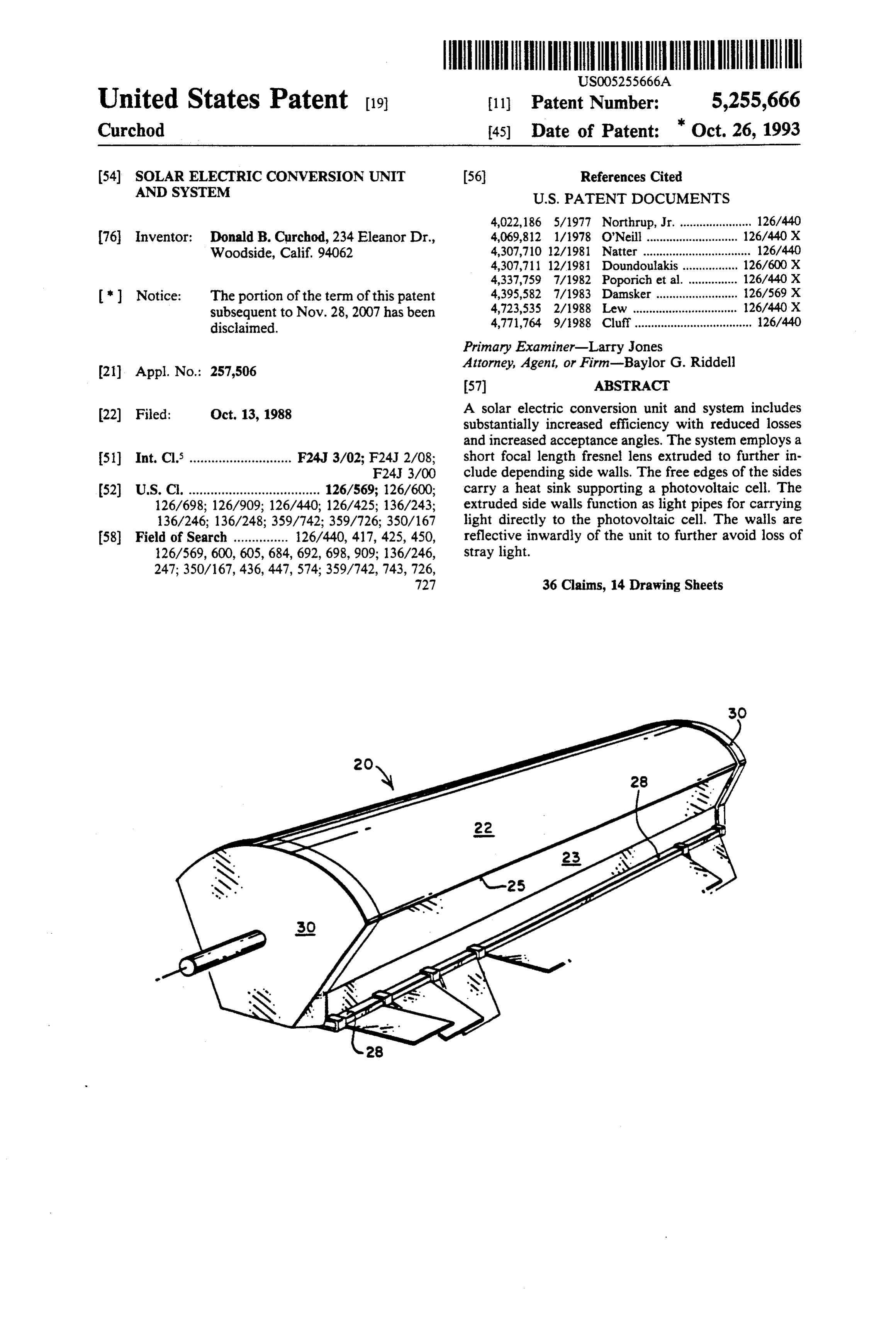
22 Filed: Oct. 13, 1988 A solar electric conversion unit and system includes substantially increased efficiency with reduced losses and increased acceptance angles. The system employs a 51) Int. Cl. ............................ F24J 3/02; F24J 2/08; short focal length fresnel lens extruded to further in F24J 3/OO clude depending side walls. The free edges of the sides 52 U.S.C. .................................... 126/569; 126/600; carry a heat sink supporting a photovoltaic cell. The 126/698; 126/909; 126/440; 126/425; 136/243; extruded side walls function as light pipes for carrying 136/246; 136/248; 359/742; 359/726; 350/167 light directly to the photovoltaic cell. The walls are 58) Field of Search ............... 26/440, 417, 425, 450, reflective inwardly of the unit to further avoid loss of 126/569, 600, 605, 684, 692, 698,909; 136/246, stray light.
Page 2
Drawing sheet — no readable text.
Page 3
Drawing sheet — no readable text.
Page 4
Drawing sheet — no readable text.
Page 5
Drawing sheet — no readable text.
Page 6
Drawing sheet — no readable text.
Page 7
Drawing sheet — no readable text.

Page 8
Drawing sheet — no readable text.
Page 9
Drawing sheet — no readable text.
Page 10
Drawing sheet — no readable text.
Page 11
Drawing sheet — no readable text.
Page 12
Drawing sheet — no readable text.
Page 13
Drawing sheet — no readable text.
Page 14
Drawing sheet — no readable text.
Page 15
Drawing sheet — no readable text.
Page 16
direction of light entering to be substantially different
SOLAR ELECTRIC CONVERSION UNT AND or displaced from the angle of light leaving the lens. As SYSTEM disclosed herein the refraction averaged across the face of the lens runs on the order of approximately 15 de
This invention pertains to a system of a type for con grees.
verting solar energy to energy in a different form, such The outside edges of the fresnel lens or top edges of as electric energy, and more particularly to such a sys the side walls which are normally joints and hence areas tem and energy conversion unit arranged and organized of losses, are shaped to collect this otherwise lost light to increase the efficiency thereof so as to minimize cost and channel it into the light pipe sides. The light passing of generation of electricity as well as cost of manufac O via the side walls is directed to the photovoltaic cell by ture of the system and unit. a tapered end section which is reflective on the outside
BACKGROUND OF THE INVENTION
surface so that the internally refracted light eventually exits the tapered section adjacent the cell.
Past designs for solar/electric conversion systems The acceptance angle of the system is greatly in have typically employed pressed fresnel lenses with 5 creased by making the sides of the module inwardly long focal lengths and small acceptance angles. These reflective so that light entering via the fresnel lens systems have sufficiently high costs as not to be suitable which strikes the sides of the module and would other for high volume manufacture. wise be lost, is reflected by the sides back to the photo Pressed fresnel lenses are used because sharp edges voltaic cell and utilized.
and good surface finish is possible, but this is at the 20 A secondary concentrating lens can be employed to expense of using straight sided or non-undercut lens tips increase the concentration ratio, giving more uniform or facets. Long focal lengths are generally necessary flux distribution either as a line or a point focus, lower with these straight vertical sided lenses in order to keep ing the amount of cell area required and decreasing the efficiency high. Some systems have used straight sided overall cost of the entire system. pressed lenses and then curved the lenses after manufac 25 The efficiency of the system can be increased by ture in a secondary operation, in order to reduce focal replacing the usual single cell with two cells, each con length without sacrificing efficiency. Both of these ap structed with a number of spaced parallel conductors proaches are costly. Also this construction employs with tops of reflective material. These two cells are side/lens joints which are wasted from a light collection disposed respectively in intersecting planes. In this way, point of view and require increased cost in surface ar 30 lost reflected light either from the cell or its overlying eaS conductors is directed to a second cell and a majority of High efficiency photovoltaic cells are normally made this otherwise reflected or lost light is used. with grid lines on their surface. These grid lines block a A further increase in efficiency is achieved by using substantial amount of light from reaching the photovol two different types of cells, wherein each "type' of cell taic cells therebeneath. Thus, wherever previous cells 35 absorbs or responds to a different particular range of have been oriented at approximately 90 degrees to the wavelengths of light. Thus, with one cell of silicon and main axis of the lens and since the grid lines thereon the other of a material such as aluminum gallium arse serve to reflect light back outside the lens to be lost, the nide (AlGaAs), light not used by one of the two cells is efficiency of the system is significantly reduced. reflected to the second cell to be used by it and a higher Solar concentrating systems which must track the sun percentage of the light spectrum is converted to electri typically have a plurality of modules which are spaced cal energy.
substantially apart, for example, in some instances by While applicant has referred throughout to conver approximately 100%, in order to avoid shadowing of sion of solar energy to electrical energy it is to be under one lens module from another when the sun is not di stood that conversion from solar energy to energy in rectly overhead, and hence, in this type of system the 45 another form such as steam can be achieved by the same space left between modules has been wasted. system by replacing the photovoltaic cell with a coil of The present invention discloses a photovoltaic gener tubing material supplied by a body of water. ating system organized and arranged to be made and The V cells can be made either to refect selective operated at far lower cost and substantially increased wavelengths from their surface or to absorb light and efficiency with reduced losses and increased acceptance 50 reflect unused wavelengths from the reflective back angles. A short focal length fresnel lens and sides are surface of the cell. A still further increase in efficiency extruded in one (or more) pieces and in such a way that and cost effectiveness in concentrating systems has been the fourth side is made up of a heat sink which carries achieved by utilizing the otherwise wasted space lo the photovoltaic cell thereon. The fresnel lens is shaped cated between modules which space is normally present with a curved top surface and lower lens facets with 55 to prevent one module from shadowing the other. To undercut lens tips to reduce short focal length losses reduce this loss the intermediate space between adja caused by shadowing between facets. These facets are cent pairs of concentrators is filled with flat plate type proportioned to minimize radial losses and material. photovoltaic cells arranged in either a V cell configura (i.e., average facet radial depth to focal length is prefer tion or in a flat configuration with a clear thin cover ably in the range of 0.8% to 3.5%). shaped to include a plurality of v-shaped surfaces. The Optical efficiency is further enhanced by utilizing the alternately spaced flat plates absorb the otherwise lost extruded side walls of the module as light pipes to carry light not used by the concentrators, thereby increasing light from the side/lens joint area via the side walls to a the efficiency of the overall system. cell. Thus, a general object of this invention is to provide The extruded lens is designed with a relatively low 65 a solar concentrator and system having substantially top curvature in order to reduce material and reflective enhanced efficiency at lower cost. losses while the lower surface of the lens is more Another object of the invention is to increase the sharply curved than the top surface. This causes the efficiency of the flat plate collectors by either a V
Page 17
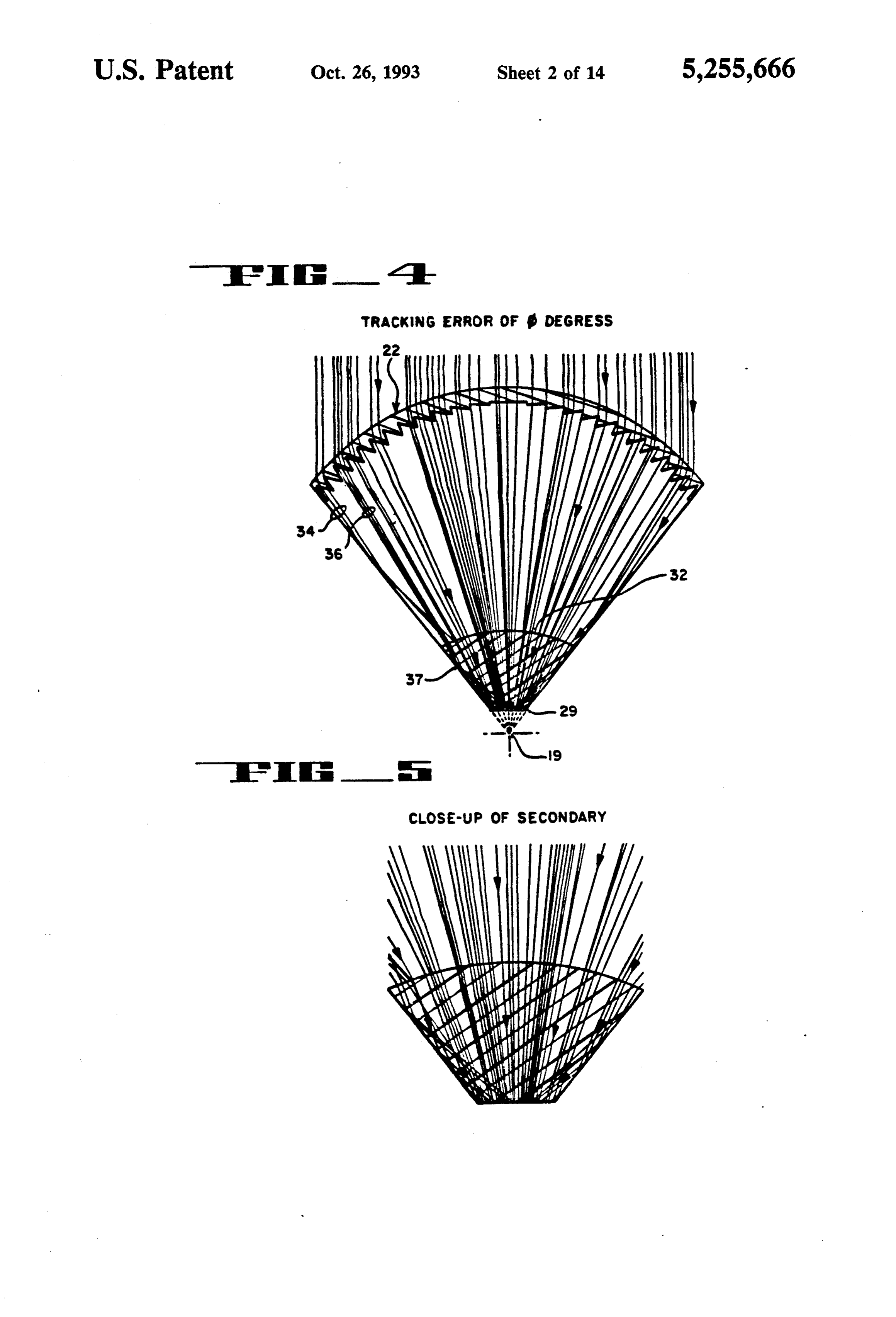
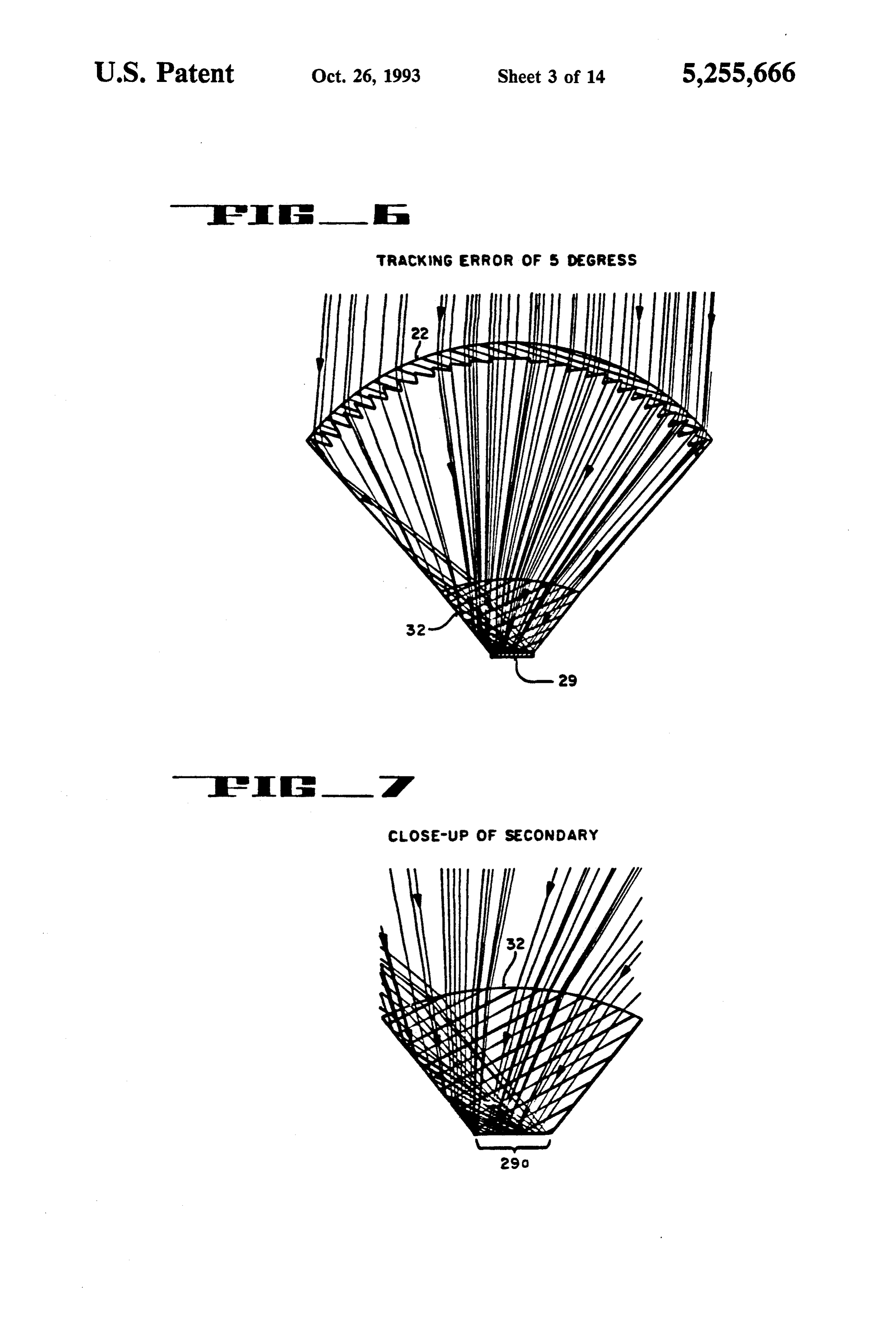
shaped configuration of the cells themselves or to have FIG. 6 shows an enlarged diagrammatic detail view the cells arranged to be flat but to have a glass or plastic as shown in FIG. 4 with the lens having a 5 degree cover shaped in a series of V's so that surface reflections tracking error;
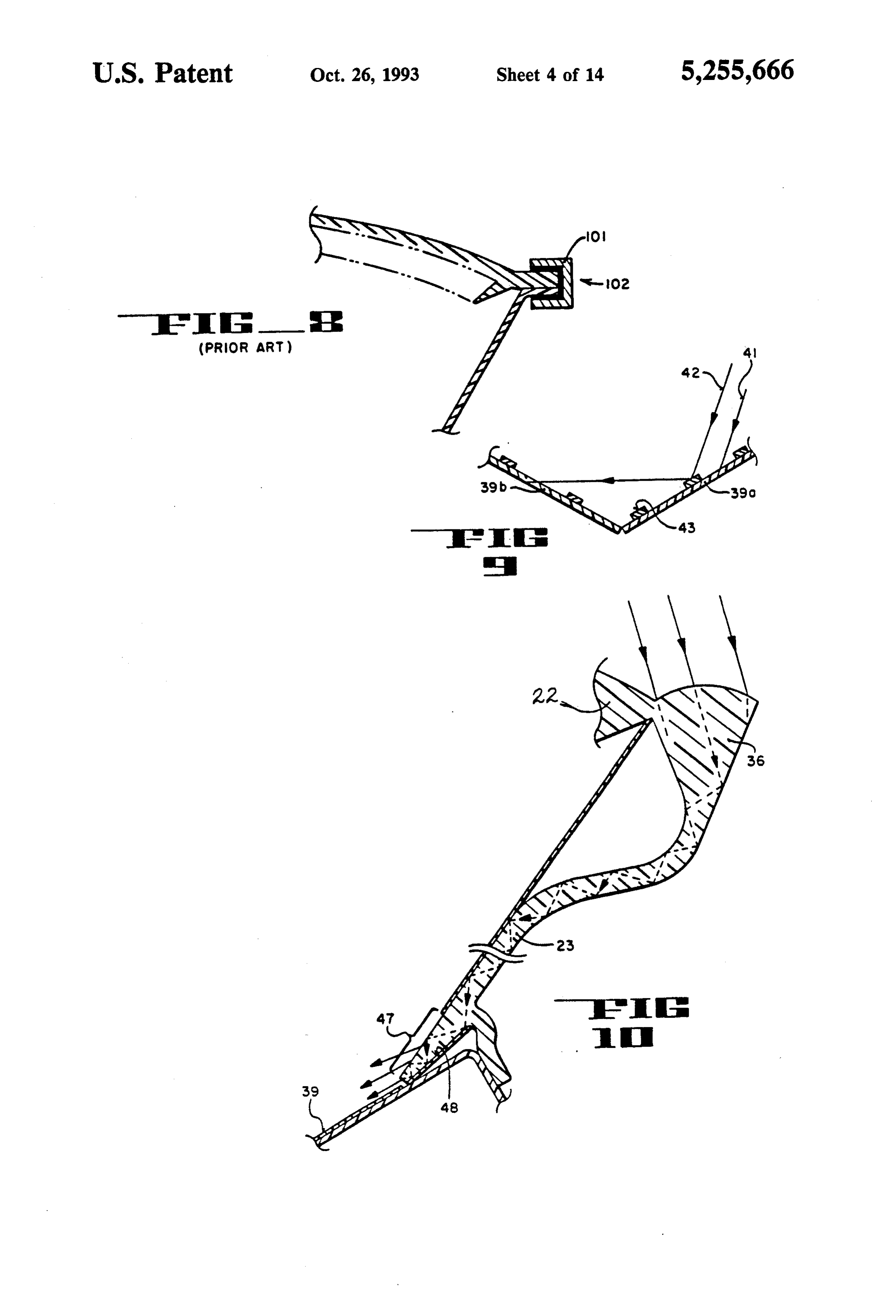
are reduced and the efficiency of the system is thereby FIG. 7 shows a further enlarged diagrammatic detail increased. 5 view of the secondary concentrator lens of FIG. 6; It is yet another object of the invention to provide a FIG. 8 shows an enlarged corner detail of a lens/wall linear concentrating collector of low concentration in connection according to the prior art; which light is simultaneously directed to the top and FIG. 9 shows an enlarged diagrammatic view in underside of the cell. A substantial increase in concen transverse section of a V-cell, according to the inven tration is then possible without reducing acceptance 10 tion;
angles. This collector can have acceptance angles of FIG. 10 shows an enlarged view of another embodi plus or minus 25 degrees by plus or minus 90 degrees ment showing the reflected light path through the side and hence will not need to track the sun, becoming far wall;
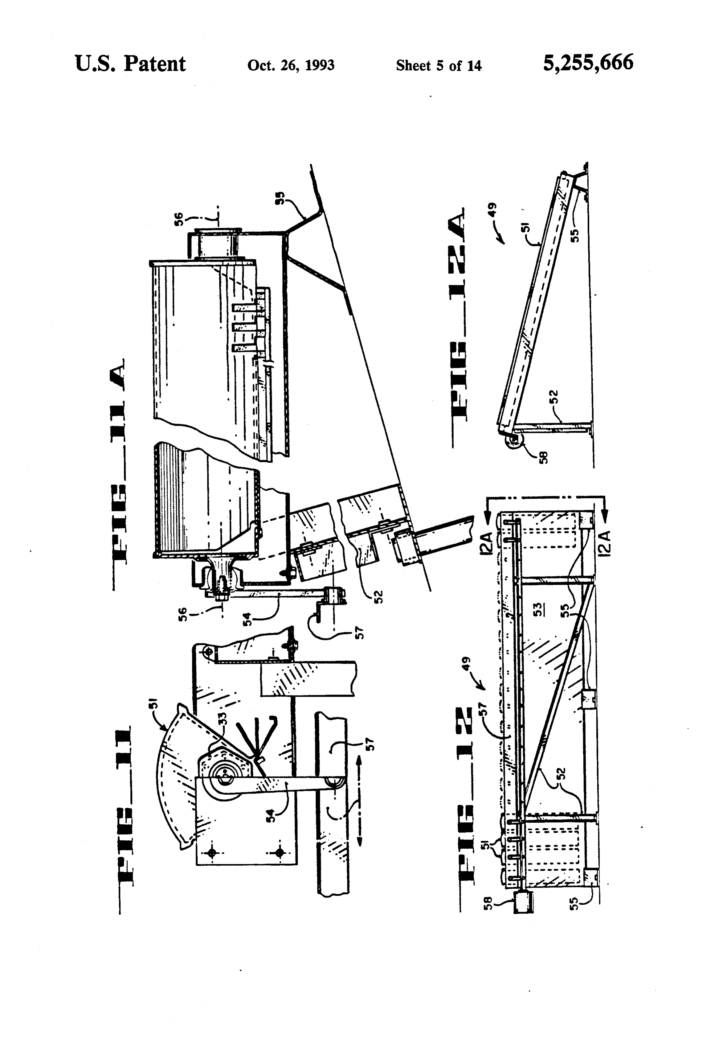
less expensive and more reliable. FIG. 11 shows an end elevation view partially in An additional object of the invention is to provide a 15 section of a single axis tracking system according to a heat sink formed to support the cell from beneath while preferred embodiment of the invention; leaving a large portion of the underside of the cell ex FIG. 11A shows a side elevation view partially in posed to sunlight. section showing the system embodiment of FIG. 11; A further object of the invention is to provide a short FIG, 12 shows a back elevation view of the system focal length fresnel lens. 20 embodiment shown in FIGS. 11, 11A; Another object of the invention is to provide a uni FIG. 12A shows a diagrammatic side elevation view tary extruded body comprising a fresnel lens and a pair of the system shown in FIG. 12 taken along line of side walls depending therefrom. 12A-12A thereof;
Yet a further object of the invention is to provide a FIG. 13 shows an enlarged diagrammatic detailed totally internally reflecting secondary lens. 25 view showing light loss using a flat, horizontal cell; Yet an additional object of the invention is to provide FIG, 14 shows an enlarged diagrammatic detail view a module with internally reflecting sides thereby form of a V cell construction capturing more light than the ing a wide acceptance angle to the unit. flat cell in FIG. 13;
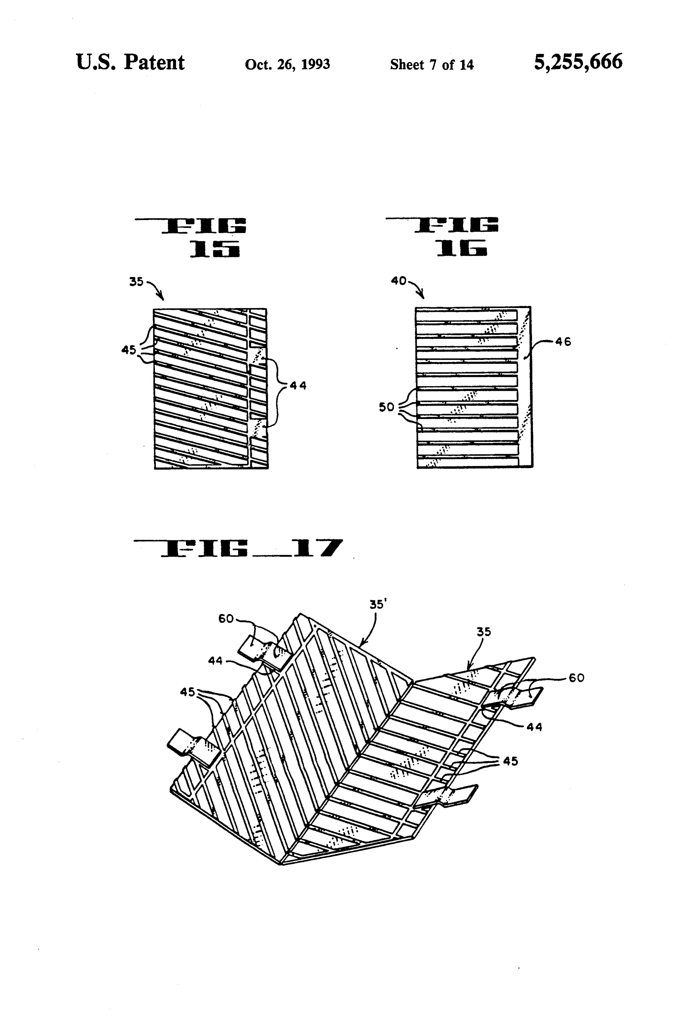
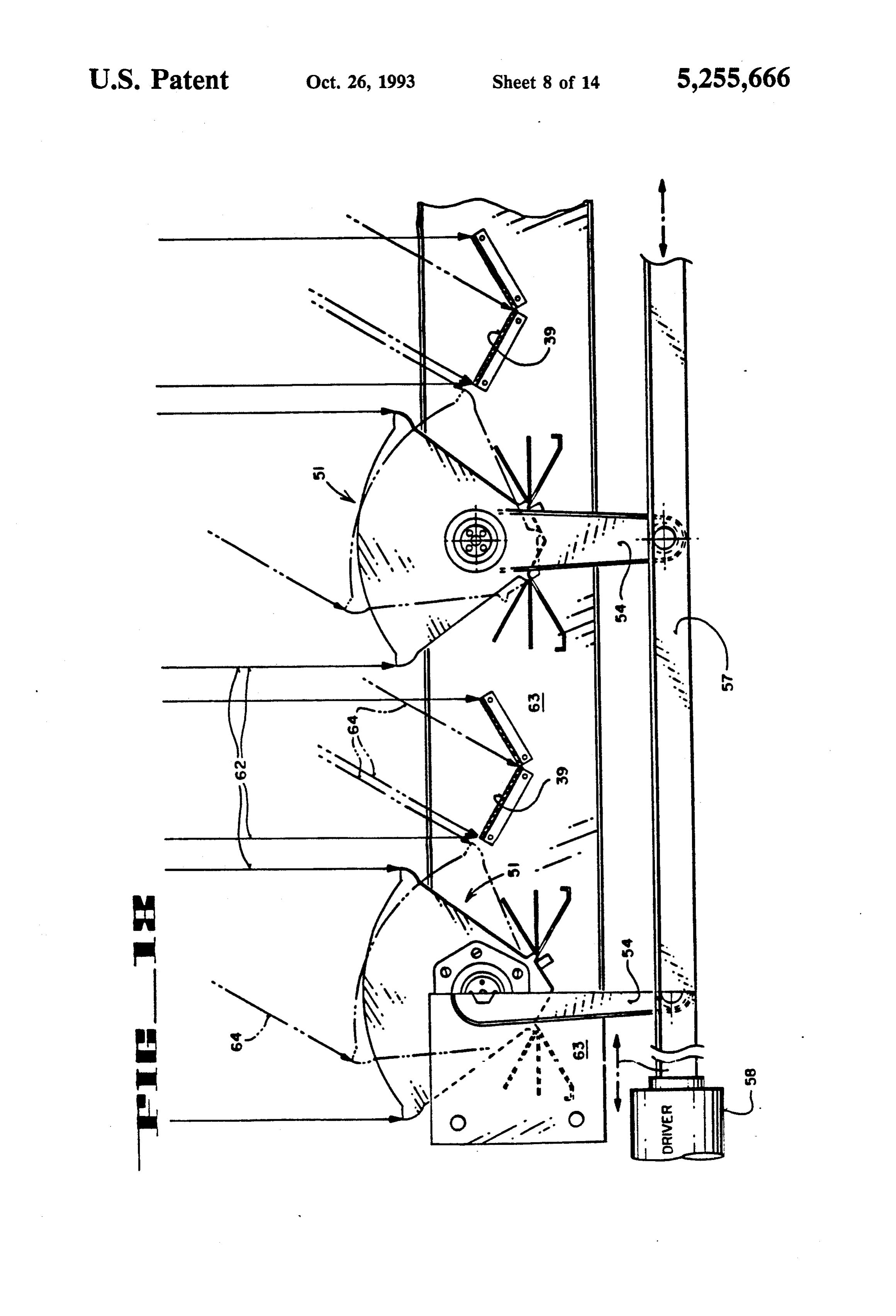
A further object of the invention is to provide a solar FIGS. 15 and 16 show enlarged diagrammatic plan concentrator which operates with single axis tracking 30 views of photovoltaic cell surfaces with conductive of the sun and provides a relatively wide tolerance at reflective traces disposed thereon; low cost. FIG. 17 shows a diagrammatic perspective V-cell Yet a further and additional object of the invention is made from a pair of cells as shown in FIG. 15; to provide a staked or snap-on heat sink secured to said FIG. 18 shows a diagrammatic end view partially in body to form a closure of the module between the 35 section according to another embodiment of the inven spaced edge margins of the side walls. tion;
An additional object of the invention is to make a FIG. 19 shows a diagrammatic perspective view large system to operate relatively inexpensively even according to yet a further embodiment of the invention with large tracking errors. featuring means for directing light to the underside of a Yet a further object of the invention is to provide 40 photovoltaic cell;
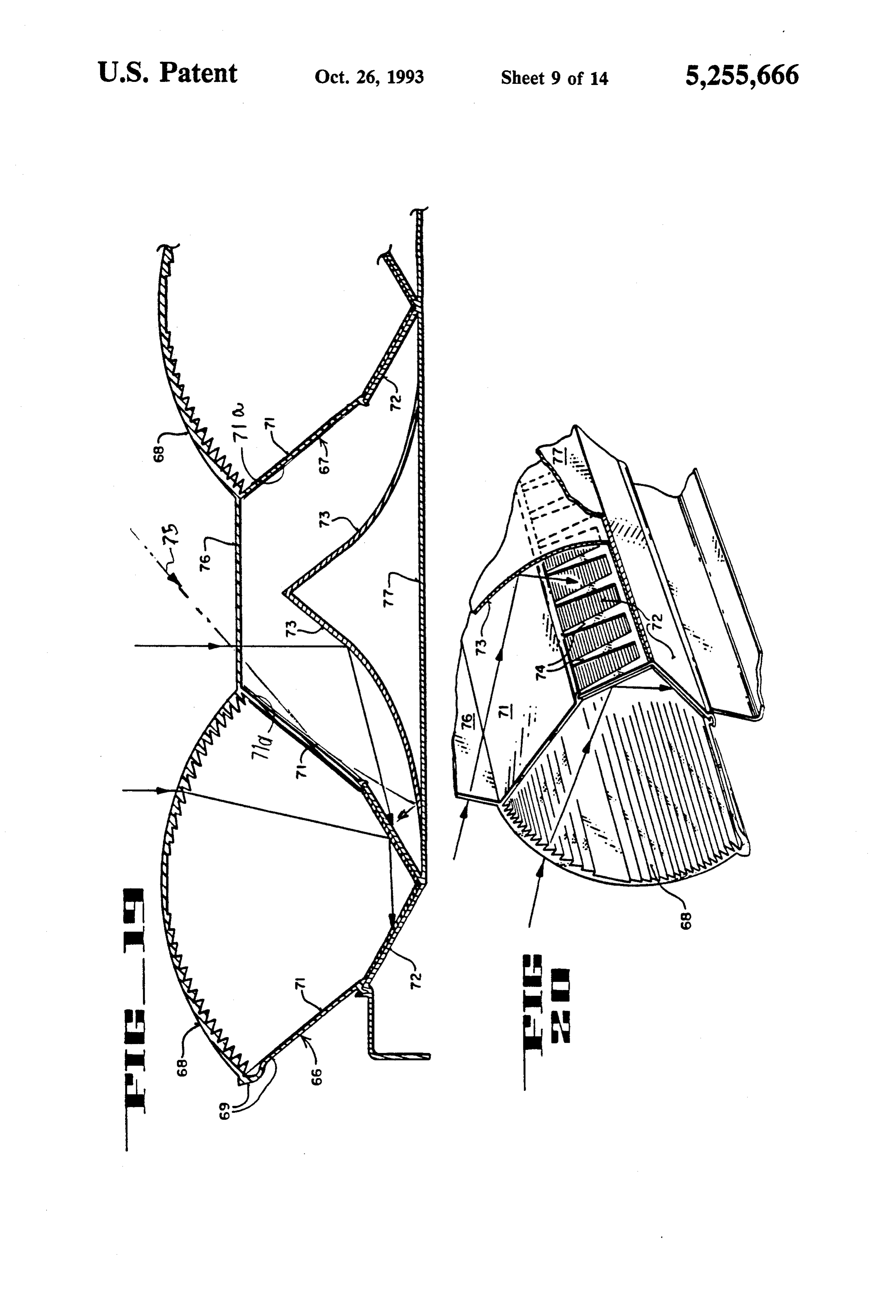
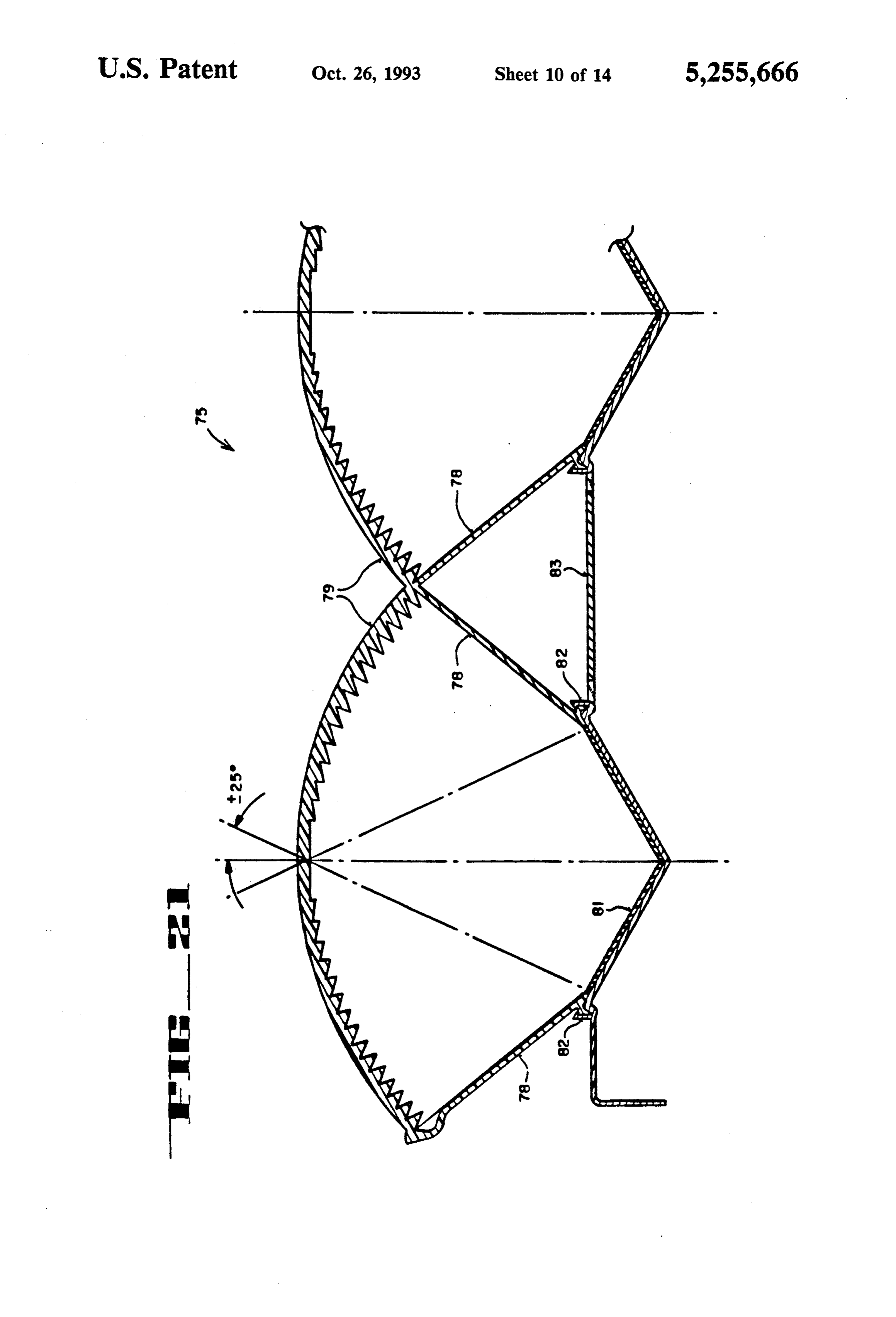
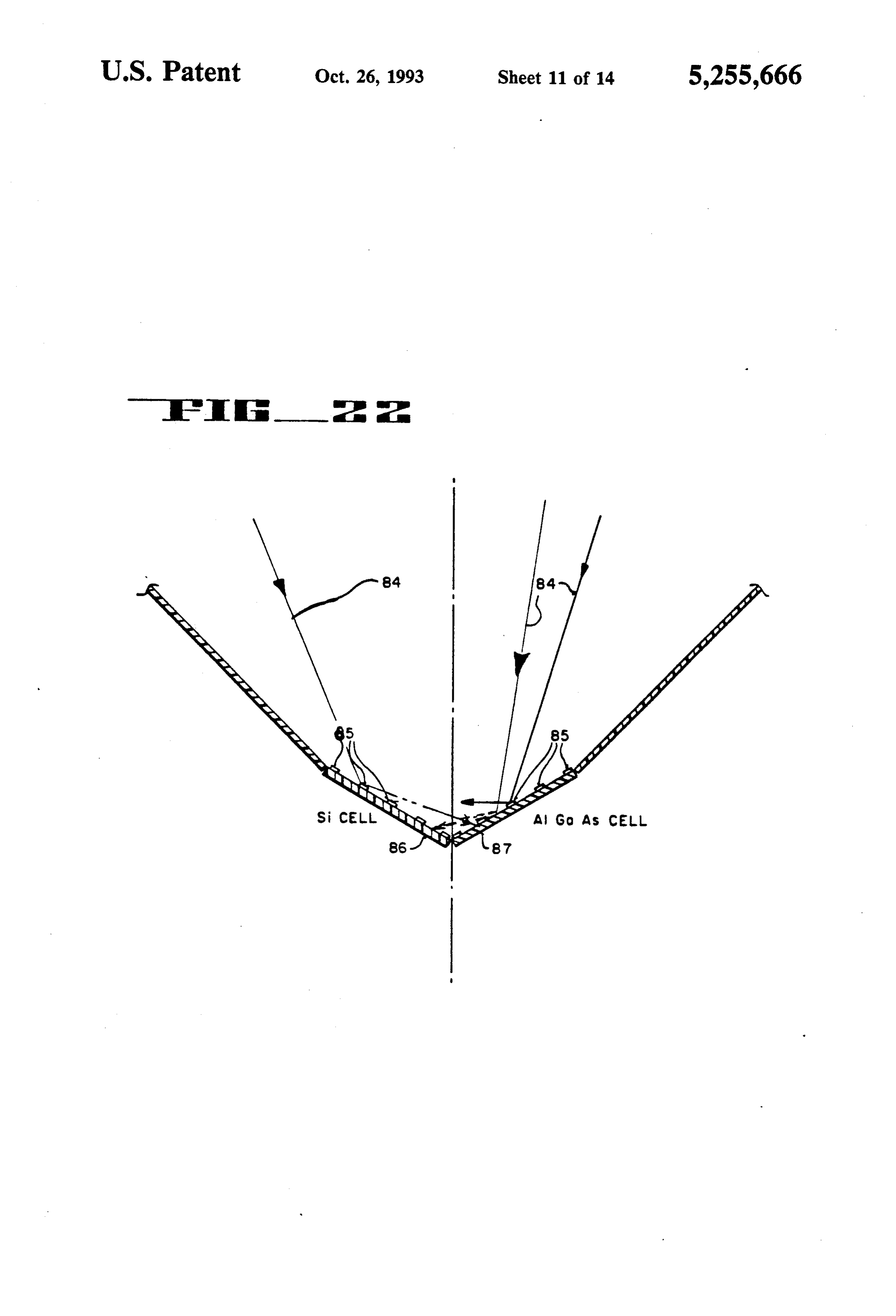
light conductive side walls to a unit of the kind de FIG. 20 shows a diagrammatic enlarged detail per scribed. spective view of a portion of FIG. 19, An additional object of the invention is to make a FIG. 21 shows a diagrammatic transverse section fresnel lens with undercut facets, in order to obtain a view of a pair of cells according to another embodiment short focal length. 45 of the invention intended to remain stationary; Yet another object of the invention is to provide a FIG. 22 shows a diagrammatic end elevation section system and unit with selective wavelength reflection view of a V cell formed to utilize a greater proportion capability so as to absorb more of the light which strikes of light directed onto a pair of cells of differing materi one or the other of the two cells of a V-cell element. als;
The foregoing and other objects of the invention will 50 FIG. 23 shows a diagrammatic end elevation section become more readily evident from the following de view of a modular unit according to another embodi tailed description of preferred embodiments when con ment of the invention;
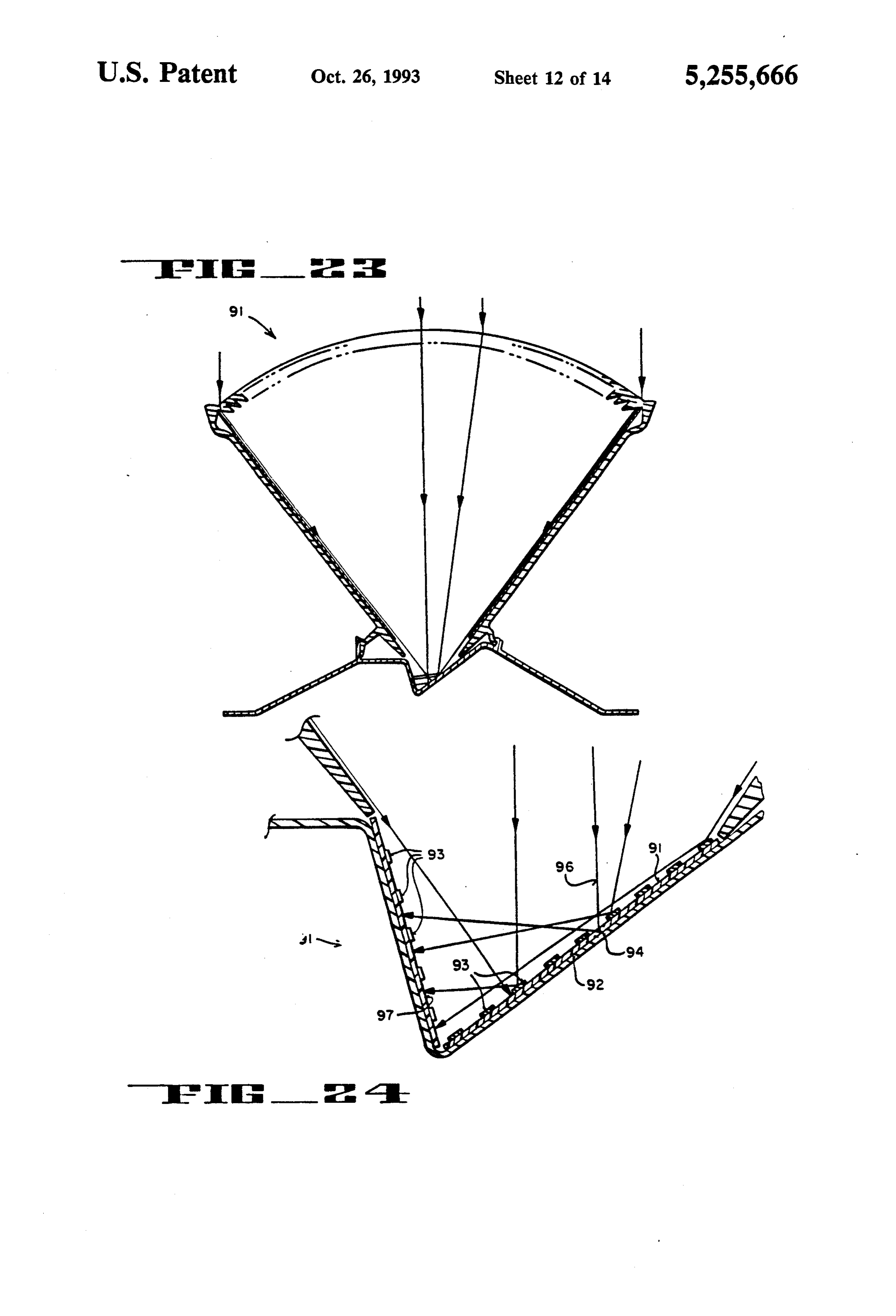
sidered in conjunction with the drawings, in which: FIG. 24 shows an enlarged lower end of FIG. 23; and FIG. 25 shows a diagrammatic end section view ac
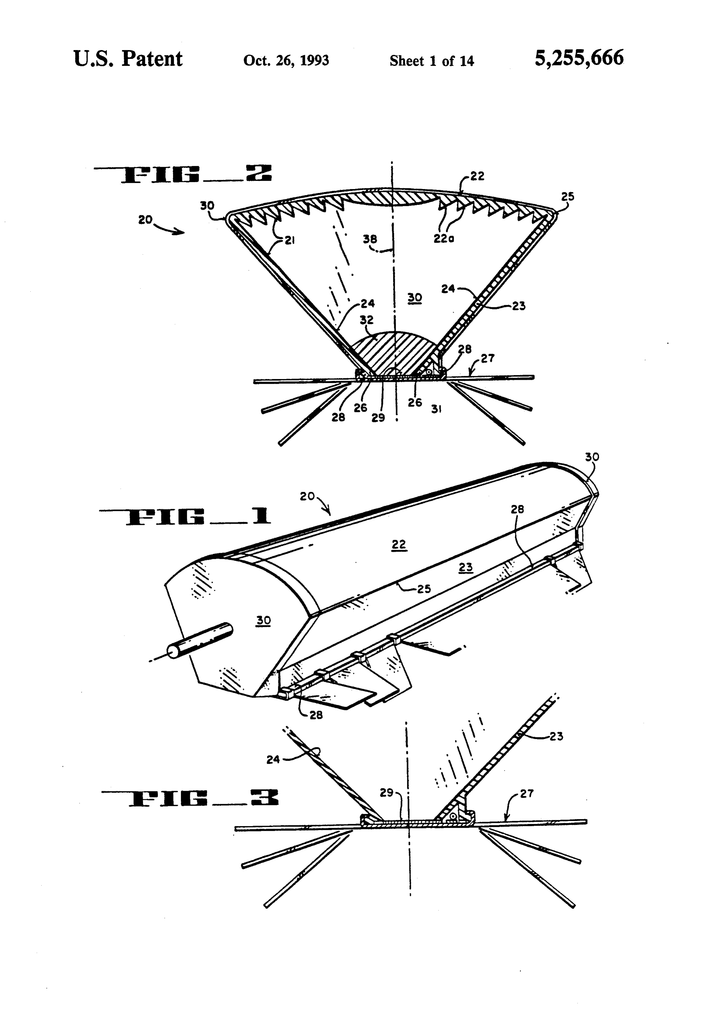
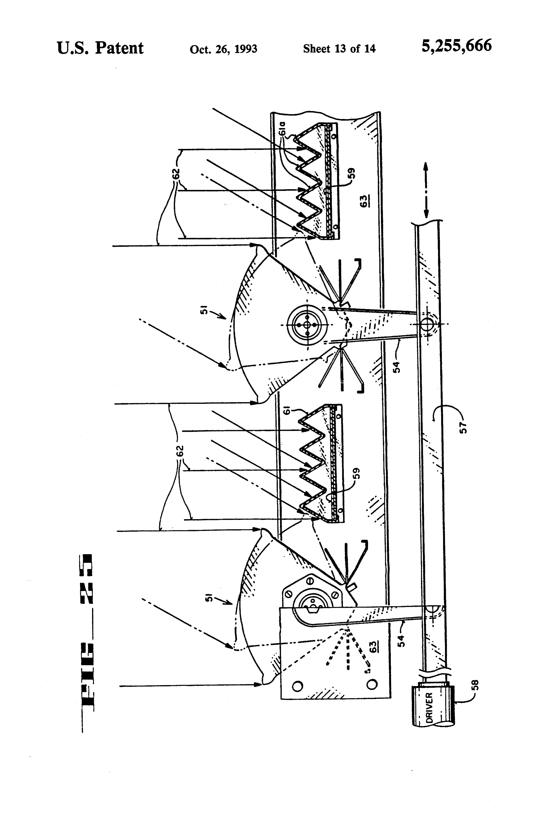
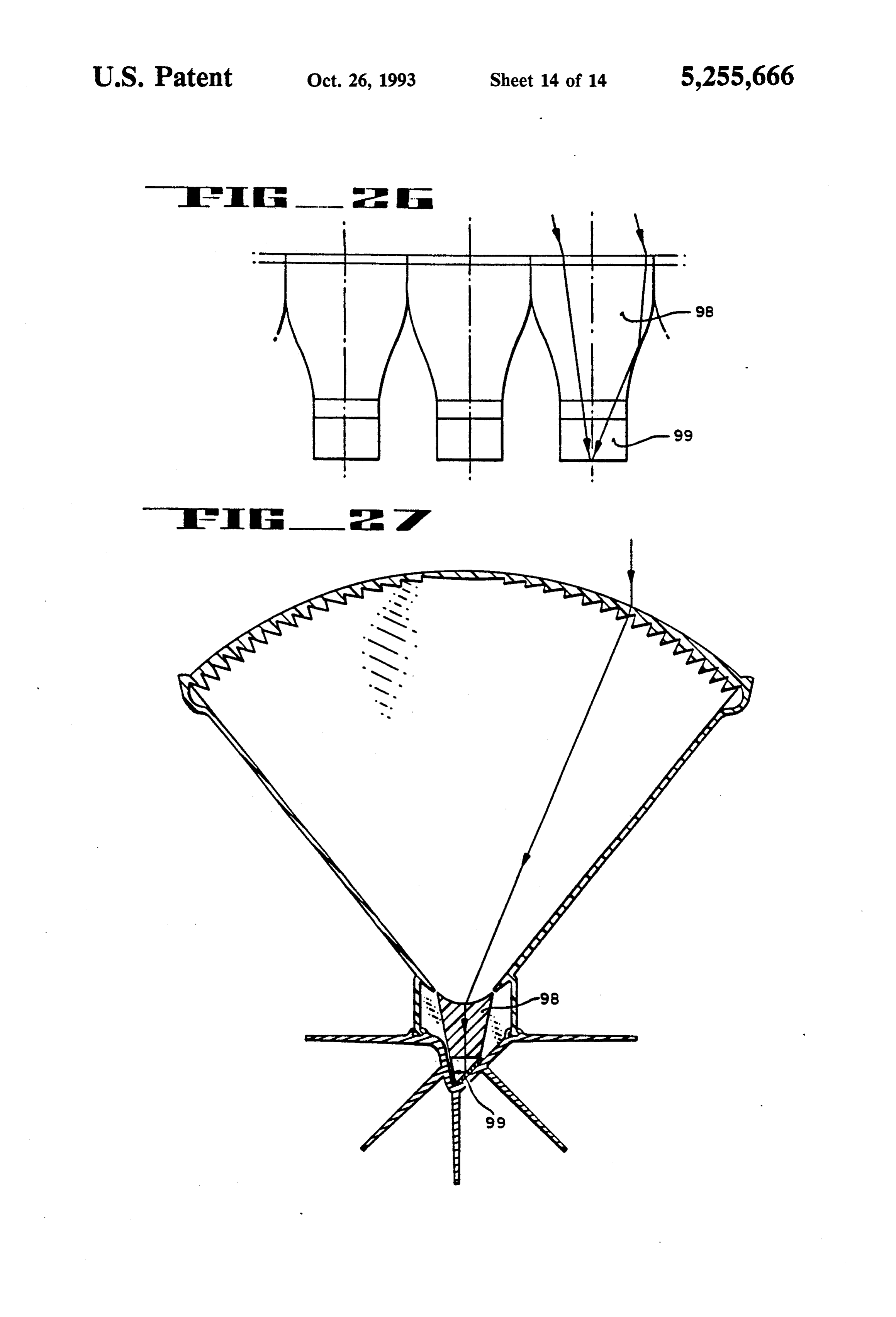
BRIEF DESCRIPTION OF THE DRAWINGS cording to yet a further embodiment of the invention. FIG. 1 shows a diagrammatic perspective view of an FIG. 26 shows a side elevation view of secondary energy conversion unit or module; concentrators providing a point focus as shown in FIG. FIG. 2 shows a transverse cross section of FIG. 1; 27; and
FIG. 3 shows an enlarged detail view of part of FIG. FIG. 27 shows a diagrammatic transverse section 2 with the secondary lens removed to form an addi- 60 view of a module according to another embodiment of tional embodiment of the invention; the invention characterized by secondary concentrators FIG. 4 shows an enlarged diagrammatic detail view for achieving a so-called point focus.
of FIG. 1 showing paths of light rays being refracted by DETAILED DESCRIPTION OF PREFERRED a fresnel lens, reflected by the side walls, refracted and EMBODIMENTS internally reflected by a secondary lens; 65
FIG. 5 shows a further enlarged diagrammatic detail FIG. 1 shows a typical solar energy conversion mod view of the secondary concentrator lens shown in FIG. ule assembly or unit 20 for converting sunlight to elec 4; trical energy. As explained further below, unit 20 is
Page 18
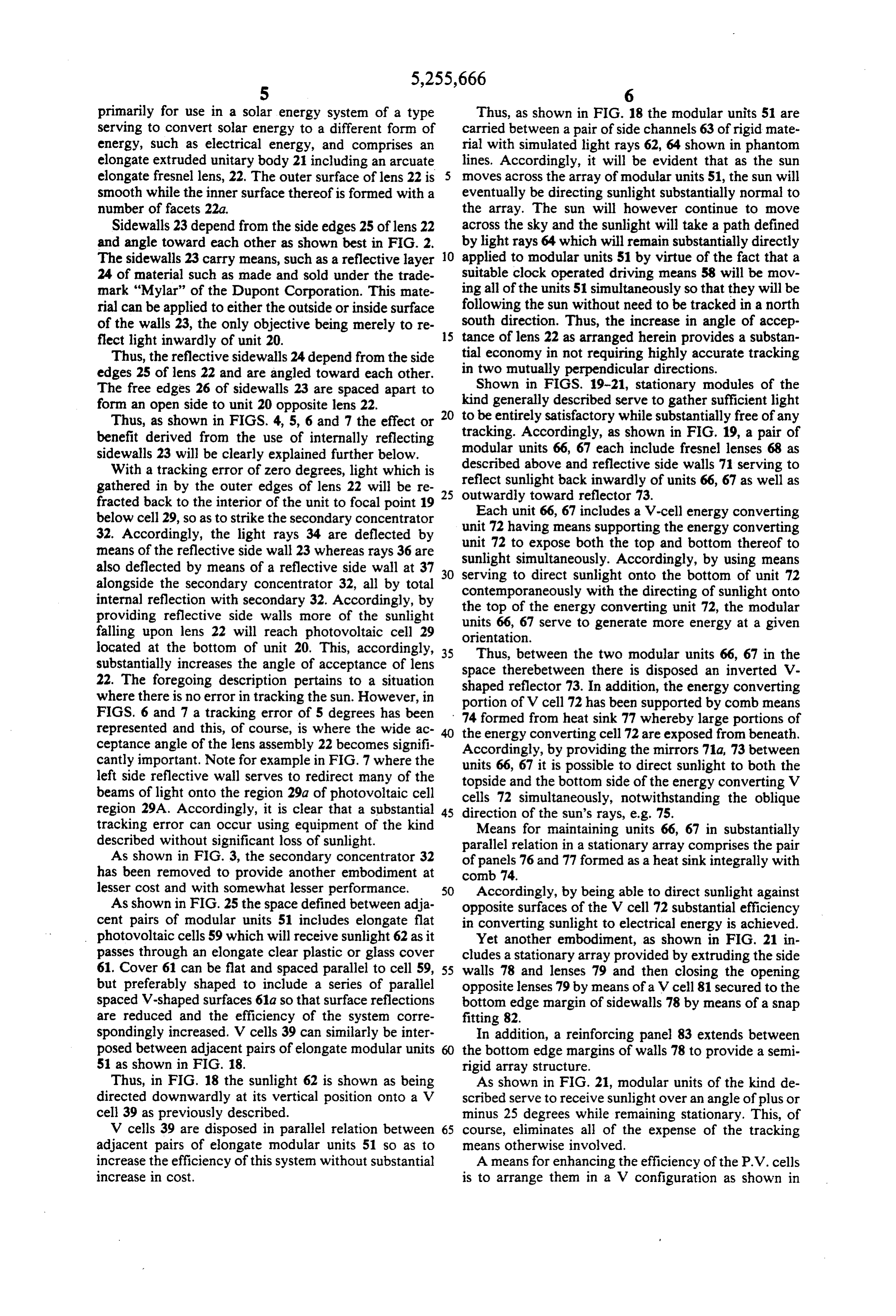
primarily for use in a solar energy system of a type Thus, as shown in FIG. 18 the modular units 51 are serving to convert solar energy to a different form of carried between a pair of side channels 63 of rigid mate energy, such as electrical energy, and comprises an rial with simulated light rays 62, 64 shown in phantom elongate extruded unitary body 21 including an arcuate lines. Accordingly, it will be evident that as the sun elongate fresnel lens, 22. The outer surface of lens 22 is 5 moves across the array of modular units 51, the sun will smooth while the inner surface thereof is formed with a eventually be directing sunlight substantially normal to number of facets 22a. the array. The sun will however continue to move Sidewalls 23 depend from the side edges 25 of lens 22 across the sky and the sunlight will take a path defined and angle toward each other as shown best in FIG. 2. by light rays 64 which will remain substantially directly The sidewalls 23 carry means, such as a reflective layer O applied to modular units 51 by virtue of the fact that a 24 of material such as made and sold under the trade suitable clock operated driving means 58 will be mov mark "Mylar" of the Dupont Corporation. This mate ing all of the units 51 simultaneously so that they will be rial can be applied to either the outside or inside surface following the sun without need to be tracked in a north of the walls 23, the only objective being merely to re south direction. Thus, the increase in angle of accep flect light inwardly of unit 20. 15 tance of lens 22 as arranged herein provides a substan Thus, the reflective sidewalls 24 depend from the side in tial economy in not requiring highly accurate tracking edges 25 of lens 22 and are angled toward each other. two mutually perpendicular directions. The free edges 26 of sidewalls 23 are spaced apart to Shown in FIGS. 19-21, stationary modules of the form an open side to unit 20 opposite lens 22. kind generally described serve to gather sufficient light Thus, as shown in FIGS. 4, 5, 6 and 7 the effect or 20 to be entirely satisfactory while substantially free of any benefit derived from the use of internally reflecting tracking. Accordingly, as shown in FIG. 19, a pair of sidewalls 23 will be clearly explained further below. modular units 66, 67 each include fresnel lenses 68 as With a tracking error of zero degrees, light which is described above and reflective side walls 71 serving to gathered in by the outer edges of lens 22 will be re 25 reflect sunlight back inwardly of units 66, 67 as well as fracted back to the interior of the unit to focal point 19 outwardly toward reflector 73. below cell 29, so as to strike the secondary concentrator unit 72 having66,means
Each unit 67 includes a V-cell energy converting supporting the energy converting 32. Accordingly, the light rays 34 are deflected by unit means of the reflective side wall 23 whereas rays 36 are sunlight simultaneously.the 72 to expose both top and bottom thereof to
Accordingly, by using means also deflected by means of a reflective side wall at 37 30 serving to direct sunlight onto the bottom of unit 72 alongside the secondary concentrator 32, all by total contemporaneously with the directing of sunlight onto internal reflection with secondary 32. Accordingly, by the top of the energy converting unit 72, the modular providing reflective side walls more of the sunlight units 66, 67 serve to generate more energy at a given falling upon lens 22 will reach photovoltaic cell 29 orientation.
located at the bottom of unit 20. This, accordingly, 35 Thus, between the two modular units 66, 67 in the substantially increases the angle of acceptance of lens space therebetween there is disposed an inverted V 22. The foregoing description pertains to a situation shaped reflector 73. In addition, the energy converting where there is no error in tracking the sun. However, in portion of V cell 72 has been supported by comb means FIGS. 6 and 7 a tracking error of 5 degrees has been 74 formed from heat sink 77 whereby large portions of represented and this, of course, is where the wide ac the energy converting cell 72 are exposed from beneath. ceptance angle of the lens assembly 22 becomes signifi Accordingly, by providing the mirrors 71a, 73 between cantly important. Note for example in FIG. 7 where the units 66, 67 it is possible to direct sunlight to both the left side reflective wall serves to redirect many of the topside and the bottom side of the energy converting V beams of light onto the region 29a of photovoltaic cell cells 72 simultaneously, notwithstanding the oblique region 29A. Accordingly, it is clear that a substantial 45 direction of the sun's rays, e.g. 75. tracking error can occur using equipment of the kind Means for maintaining units 66, 67 in substantially described without significant loss of sunlight. parallel relation in a stationary array comprises the pair As shown in FIG. 3, the secondary concentrator 32 of panels 76 and 77 formed as a heat sink integrally with has been removed to provide another embodiment at comb 74.
lesser cost and with somewhat lesser performance. 50 Accordingly, by being able to direct sunlight against As shown in FIG. 25 the space defined between adja opposite surfaces of the V cell 72 substantial efficiency cent pairs of modular units 51 includes elongate flat in converting sunlight to electrical energy is achieved. photovoltaic cells 59 which will receive sunlight 62 as it Yet another embodiment, as shown in FIG. 21 in passes through an elongate clear plastic or glass cover cludes a stationary array provided by extruding the side 61. Cover 61 can be flat and spaced parallel to cell 59, 55 walls 78 and lenses 79 and then closing the opening but preferably shaped to include a series of parallel opposite lenses 79 by means of a V cell 81 secured to the spaced V-shaped surfaces 61a so that surface reflections bottom edge margin of sidewalls 78 by means of a snap are reduced and the efficiency of the system corre fitting 82.
spondingly increased. V cells 39 can similarly be inter In addition, a reinforcing panel 83 extends between posed between adjacent pairs of elongate modular units the bottom edge margins of walls 78 to provide a semi 51 as shown in FIG. 18. rigid array structure.
Thus, in FIG. 18 the sunlight 62 is shown as being As shown in FIG. 21, modular units of the kind de directed downwardly at its vertical position onto a V scribed serve to receive sunlight over an angle of plus or cell 39 as previously described. minus 25 degrees while remaining stationary. This, of V cells 39 are disposed in parallel relation between 65 course, eliminates all of the expense of the tracking adjacent pairs of elongate modular units 51 so as to means otherwise involved.
increase the efficiency of this system without substantial A means for enhancing the efficiency of the P.V. cells increase in cost. is to arrange them in a V configuration as shown in
Page 19
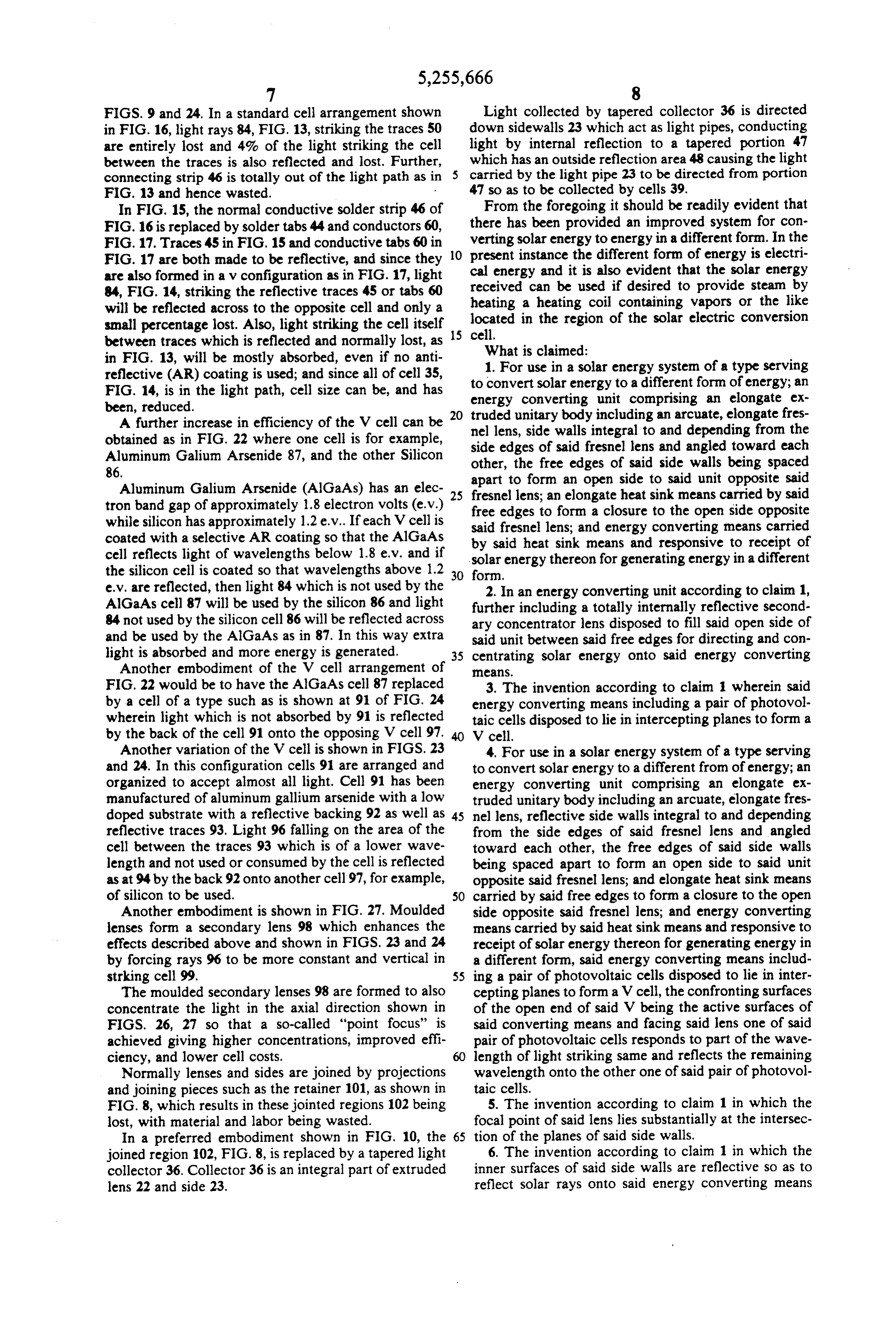
FIGS. 9 and 24. In a standard cell arrangement shown Light collected by tapered collector 36 is directed in FIG. 16, light rays 84, FIG. 13, striking the traces 50 down sidewalls 23 which act as light pipes, conducting are entirely lost and 4% of the light striking the cell light by internal reflection to a tapered portion 47 between the traces is also reflected and lost. Further, which has an outside reflection area 48 causing the light connecting strip 46 is totally out of the light path as in 5 carried by the light pipe 23 to be directed from portion FIG. 13 and hence wasted. 47 so as to be collected by cells 39. In FIG. 15, the normal conductive solder strip 46 of From the foregoing it should be readily evident that FIG. 16 is replaced by solder tabs 44 and conductors 60, there has been provided an improved system for con FIG. 17. Traces 45 in FIG, 15 and conductive tabs 60 in verting solar energy to energy in a different form. In the FIG. 17 are both made to be reflective, and since they 10 cal present instance the different form of energy is electri are also formed in a v configuration as in FIG. 17, light energy and it is also evident that the solar energy received can be used if desired to provide steam by 84, FIG. 14, striking the reflective traces 45 or tabs 60 heating will be reflected across to the opposite cell and only a a heating coil containing vapors or the like located small percentage lost. Also, light striking the cell itself 15 cell. in the region of the solar electric conversion between traces which is reflected and normally lost, as What is claimed:
in FIG. 13, will be mostly absorbed, even if no anti reflective (AR) coating is used; and since all of cell 35, to 1.convert
For use in a solar energy system of a type serving solar energy to a different form of energy; an
FIG. 14, is in the light path, cell size can be, and has energy converting unit comprising an elongate ex been, reduced. 20 truded unitary body including an arcuate, elongate fres A further increase in efficiency of the V cell can be obtained as in FIG. 22 where one cell is for example, nel lens, side walls integral to and depending from the Aluminum Galium Arsenide 87, and the other Silicon other,edges side the of said fresnel lens and angled toward each free edges of said side walls being spaced 86. apart to form an open side to said unit opposite said Aluminum Galium Arsenide (AlGaAs) has an elec 25 fresnel lens; an elongate heat sink means carried by said tron band gap of approximately 1.8 electron volts (e.v.) free edges to form a closure to the open side opposite while silicon has approximately 1.2 e.v. If each V cell is said fresnel lens; and energy converting means carried coated with a selective AR coating so that the AlGaAs by said heat sink means and responsive to receipt of cell reflects light of wavelengths below 1.8 e.v. and if solar energy thereon for generating energy in a different the silicon cell is coated so that wavelengths above 1.2 30 form.
e.v. are reflected, then light 84 which is not used by the 2. In an energy converting unit according to claim 1, AlGaAs cell 87 will be used by the silicon 86 and light further including a totally internally reflective second 84 not used by the silicon cell 86 will be reflected across ary concentrator lens disposed to fill said open side of and be used by the AlGaAs as in 87. In this way extra said unit between said free edges for directing and con light is absorbed and more energy is generated. 35 centrating solar energy onto said energy converting Another embodiment of the V cell arrangement of eans.
FIG.22 would be to have the AlGaAs cell 87 replaced 3. The invention according to claim 1 wherein said by a cell of a type such as is shown at 91 of FIG. 24 energy converting means including a pair of photovol wherein light which is not absorbed by 91 is reflected taic cells disposed to lie in intercepting planes to form a by the back of the cell 91 onto the opposing V cell 97. V cell.
Another variation of the V cell is shown in FIGS. 23 4. For use in a solar energy system of a type serving and 24. In this configuration cells 91 are arranged and to convert solar energy to a different from of energy; an organized to accept almost all light. Cell 91 has been energy converting unit comprising an elongate ex manufactured of aluminum gallium arsenide with a low truded unitary body including an arcuate, elongate fres doped substrate with a reflective backing 92 as well as 45 nel lens, reflective side walls integral to and depending reflective traces 93. Light 96 falling on the area of the from the side edges of said fresnel lens and angled cell between the traces 93 which is of a lower wave toward each other, the free edges of said side walls length and not used or consumed by the cell is reflected being spaced apart to form an open side to said unit as at 94 by the back 92 onto another cell 97, for example, opposite said fresnel lens; and elongate heat sink means of silicon to be used. 50 carried by said free edges to form a closure to the open Another embodiment is shown in FIG. 27. Moulded side opposite said fresnel lens; and energy converting lenses form a secondary lens 98 which enhances the means carried by said heat sink means and responsive to effects described above and shown in FIGS. 23 and 24 receipt of solar energy thereon for generating energy in by forcing rays 96 to be more constant and vertical in a different form, said energy converting means includ strking cell 99. 55 ing a pair of photovoltaic cells disposed to lie in inter The moulded secondary lenses 98 are formed to also cepting planes to form a V cell, the confronting surfaces concentrate the light in the axial direction shown in of the open end of said V being the active surfaces of FIGS. 26, 27 so that a so-called "point focus' is said converting means and facing said lens one of said achieved giving higher concentrations, improved effi pair of photovoltaic cells responds to part of the wave ciency, and lower cell costs. length of light striking same and reflects the remaining Normally lenses and sides are joined by projections wavelength onto the other one of said pair of photovol and joining pieces such as the retainer 101, as shown in taic cells.
FIG. 8, which results in these jointed regions 102 being 5. The invention according to claim 1 in which the lost, with material and labor being wasted. focal point of said lens lies substantially at the intersec In a preferred embodiment shown in FIG, 10, the 65 tion of the planes of said side walls.
joined region 102, FIG. 8, is replaced by a tapered light 6. The invention according to claim 1 in which the collector 36. Collector 36 is an integral part of extruded inner surfaces of said side walls are reflective so as to lens 22 and side 23. reflect solar rays onto said energy converting means
Page 20
whenever said lens is misdirected with respect to a light thereon for generating energy in the different form SOC. wherein said energy converting means comprises a pair 7. The invention as in claim 6 further in which said of photovoltaic cells disposed to lie in intercepting energy conversion means lies in each of a pair of planar planes to form a V cell means supporting said energy members disposed to form a V shaped end view. converting cell to expose both the top and bottom 8. For use in a solar energy system of a type serving thereof to sunlight, and means serving to direct sunlight to convert solar energy to a different form of energy; an onto said bottom contemporaneously with the direction energy converting unit comprising an elongate ex of sunlight onto the top of said energy converting truded unitary body including an arcuate, elongate fres means so as to generate more energy at a given position. nel lens, the outer surface of said lens being smooth and O 14. For use in a solar energy system of a type serving the inner surface being formed with a number of facets to convert solar energy to a different form of energy; an thereon; reflective side walls depending from the side energy converting unit comprising an elongate ex edges of said fresnel lens and angled toward each other, truded unitary body having an arcuate elongate fresnel the free ends of said side walls being spaced apart to lens, the outer surface of said lens being smooth; reflec form an open side to said unit opposite said fresnel lens; 15 tive side walls depending from the side edges of said an elongate heat sink means carried by said free edges to lens and angled toward each other to form an open side form a closure to the open side opposite said fresnel to said body opposite said fresnel lens; means for closing lens; and energy converting means carried by said heat said open side comprising an elongate panel forming a sink means and responsive to receipt of solar energy heat sink secured to the bottom edges of said side walls; thereon for generating energy in the different form said and photovoltaic cell means for converting solar energy side walls include a plurality of light concentrators and to energy in a different form, said cell means being light pipe means therein originating adjacent the side carried by said panel.
edges of said fresnel lens, said side wall light pipe means 15. The invention according to claim 14 in which said serving to direct light therethrough to be discharged panel is formed along the side edges thereof to engage onto said photovoltaic cells. 25 the edge margins of the sides of said body to retain said 9. The invention according to claim 8 in which the panel thereto.
bottom inner edge margin is transparent discharging 16. For use in a solar/electric system as energy con light therethrough, and the bottom outer edge margin verting means serving to convertsolar energy to electri lies at an angle converging with respect to the bottom cal energy comprising first and second photovoltaic inner edge margin and means forming a reflective sur 30 cells, each cell carrying a plurality of spaced parallel face on the bottom outer edge margin serving to direct reflective traces extending thereacross; said reflective light from within the side wall onto said photovoltaic traces forming operative active portions of said energy cell. converting means, said photovoltaic cells lying in inter 10. A solar energy system of a type serving to convert secting planes respectively to form a V-cell therefrom solar energy to a different form of energy comprising a 35 in order to reflect unused light from one cell to the plurality of elongate energy converting units disposed other.
to form an array thereof and disposed to lie in a plane; 17. For use in a solar/electric system an energy con each said unit being supported on an associated axis to verting means serving to convert solar to electric en be tipped between advanced and retracted positions; ergy comprising an elongate flat photovoltaic cell and a means coupled to each said unit for moving said units clear cover overlying same in closely spaced relation; conjointly between said positions at a rate correspond said clear cover being formed to include a series of ing to the rate of movement of the sun thereacross. elongate parallel spaced V-shaped surfaces lying sub 11. A solar energy system as in claim 10 wherein said stantially in a plane and serving to reduce surface reflec units are spaced laterally apart sufficiently to accommo tions and thereby to enhance the efficiency of said cell. date said movements between advanced and retracted 45 18. In a system for converting solar energy into elec positions thereby leaving predetermined open spacing tricity, a module comprising an extruded linear fresnel therebetween, a supplementary energy converting unit lens carrying at the sides thereof extruded side walls, a carried in said spacings, said supplementary energy heat sink extending between said side walls at a position converting units comprising elongate photo-voltaic cell remote from said lens, and a photovoltaic cell carried means lying in said spacing. 50 by said heat sink.
12. The invention according to claim 11 in which said 19. A system as in claim 18 in which said side walls supplementary unit comprises a pair of photovoltaic are reflective to reflect light inwardly of said module. cells disposed to lie in intercepting planes to form a V 20. A system as in claim 18 in which said fresnel lens shaped cell therebetween. has a short focal length.
13. For use in a solar energy system of a type serving 55 21. A system as in claim 18 in which said lens has a to convert solar energy to a different form of energy; an short focal length and said side walls are reflective to energy converting unit comprising an elongate ex direct light from said lens inwardly of said module. truded unitary body including an arcuate, elongate fres 22. In a system according to claim 18 in which said nel lens, the outer surface of said lens being smooth and lens comprises a short focus fresnel lens in which the. the inner surface being formed with a number of facets focal point is disposed on the remote side of said cell thereon; reflective side walls depending from the side with respect to said lens.
edges of said fresnel lens and angled toward each other, 23. In a system according to claim 18 in which said the free edges of said side walls being spaced apart to lens and side walls are integrally extruded together. form anopen side to said unit opposite said fresnel lens; 24. In a system according to claim 18 in which said an elongate heat sink means carried by said free edges to 65 heat sink snaps together with said side walls to form a form a closure to the open side opposite said fresnel closure therebetween.
lens; and energy converting means carried by said heat 25. In a system according to claim 18 further includ sink means and responsive to receipt of solar energy ing a secondary lens carried between the lower edge
Page 21
margins of said side walls for further concentrating said said V shaped cell carrying active elements thereof for Solar energy onto said cell. converting solar energy to electrical energy. 26. In a system as in claim 25 in which said secondary pair31.ofIncells a system according to claim 30 in which said each carries conductive reflective traces lens has been formed as an extruded portion of one of 5 thereon exposed to light, said traces forming active said side walls. portions of each said cell.
27. In a system according to claim 26 wherein said 32. In a system according to claim 31 in which said side walls function as light pipes for carrying light col reflective conductive traces of said pair of cells are lected by said region to said cell. respectively disposed to be angled in opposite direc 28. In a system as in claim 15 comprising a plurality of 10 tions.
said units in which said side walls carry reflective mate 33. In a system according to claim 30 in which at least rial on both the inner and outer sides thereof, and an one of said pair of cells carries a reflective backing, the inverted V shaped reflector disposed between adjacent reflective surface of said backing facing the back sur face of said cell.
pairs of said units, the side walls of said units confront 15 34. In a fresnel lens system wherein the average radial ing said reflector serving to reflect light received at an depth of the facets to the focal length of said lens as a oblique angle and to redirect such light onto the under percentage thereof lies substantially in the range be side of said cell via said reflector, said heat sink having tween 0.8 to 3.5 percent.
open portions thereto exposing the underside of said 35. In a photovoltaic solar cell comprising plural V cell to light reflected onto it. 20 cell means; reflective trace means carried by said V cell 29. In a system for converting solar energy into elec means and angled with respect to each other to form tricity comprising a photovoltaic cell, an elongate lens intersecting planes, said trace means serving to form and side walls depending therefrom, said walls and lens active portions of said cell, and reflective conductive being extruded together to form an integral joint there 25 tially all said disposed connections
V cell and arranged to locate substan mens to be exposed to light.
between, said joint forming a light collecting region. 36. In a photovoltaic solar generating system an array 30. In a system for converting solar energy to elec comprising fixed modules and movable modules, said tricity an improved photovoltaic cell assembly compris movable modules being disposed to track the sun in a ing a pair of photovoltaic cells disposed adjacent each given direction, said movable and fixed modules being other, said cells lying respectively in intersecting planes 30 disposed alternately across said array.
to form a V shape cell assembly, the front surfaces of
Provenance
- Collection
- Cited prior art
- Original PDF
- patentimages.storage.googleapis.com →
- Filed
- 1988-10-13
- Pages
- 21
- Method
- pdftotext (the PDF's own text layer) + pdftoppm 300dpi page scans
- Source
- Google Patents bibliographic record
- Granted
- 1993-10-26
- Inventors
- Donald B. Curchod
- Transcribed from
- patentimages.storage.googleapis.com →