patent · US4723535
Solar trap
9 February 1988
Page 1 — bibliographic record
United States Patent (19) 11 Patent Number: 4,723,535 Lew 45 Date of Patent: Feb. 9, 1988 (54 SOLAR TRAP 4,092,979 6/1978 Kotlarz ........................... 26/440 X 4,230,094 10/1980 Szulmayer ........................... 126/439 (76) Inventor: Hyok S. Lew, 7890 Oak St., Arvada, Primary Examiner-Larry Jones
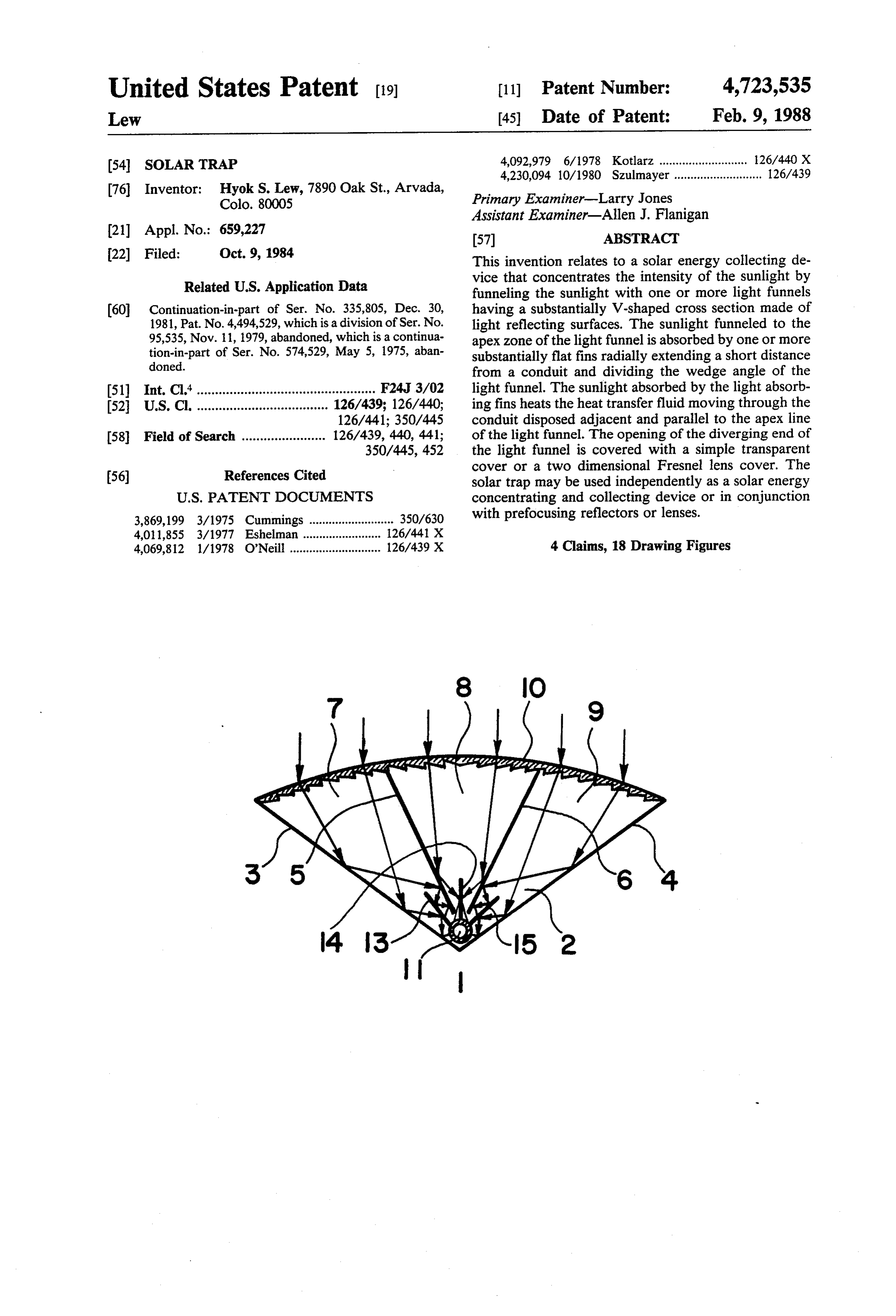
Assistant Examiner-Allen J. Flanigan (21) Appl. No.: 659,227 57 ABSTRACT 22) Filed: Oct. 9, 1984 This invention relates to a solar energy collecting de Related U.S. Application Data vice that concentrates the intensity of the sunlight by funneling the sunlight with one or more light funnels (60) Continuation-in-part of Ser. No. 335,805, Dec. 30, having a substantially V-shaped cross section made of 1981, Pat. No. 4,494,529, which is a division of Ser. No. light reflecting surfaces. The sunlight funneled to the 95,535, Nov. 11, 1979, abandoned, which is a continua apex zone of the light funnel is absorbed by one or more tion-in-part of Ser. No. 574,529, May 5, 1975, aban substantially flat fins radially extending a short distance doned. from a conduit and dividing the wedge angle of the (51) Int. Cl'................................................. F24J 3/02 light funnel. The sunlight absorbed by the light absorb 52 U.S. C. .................................... 126/439; 126/440; ing fins heats the heat transfer fluid moving through the 126/441; 350/445 conduit disposed adjacent and parallel to the apex line (58 Field of Search ....................... 126/439, 440, 441; of the light funnel. The opening of the diverging end of 350/445, 452 the light funnel is covered with a simple transparent cover or a two dimensional Fresnel lens cover. The 56) References Cited solar trap may be used independently as a solar energy
3,869,199 3/1975 Cummings .......................... 350/630 with prefocusing reflectors or lenses. 4,011,855 3/1977 Eshelman ..... ... 126/441 X 4,069,812 1/1978 O'Neill ............................ 126/439 X 4 Claims, 18 Drawing Figures
Page 2
Drawing sheet — no readable text.
Page 3
Drawing sheet — no readable text.
Page 4
Still a further object of the present invention is to
SOLAR TRAP provide a light funnel directing sunlight to a one sided photovoltaic cell panel disposed in the apex zone of the
This application is a continuation-in-part of patent light funnel that faces the opening of the light funnel. application Ser. No. 335,805, filed 12/30/81, now U.S. 5 become These and other objects of the present invention will Pat. No. 4,494,529, which is a division of patent applica clear as the description thereof proceeds. tion Ser. No. 095,535, filed 11/11/79, now abandoned, BRIEF DESCRIPTION OF FIGURES which is a continuation-in-part of patent application
Ser. No. 574,529, filed 5/5/75, now abandoned. The present invention may be described with a 10 greater clarity and specificity by referring to the follow
BACKGROUND OF THE INVENTION ing figures:
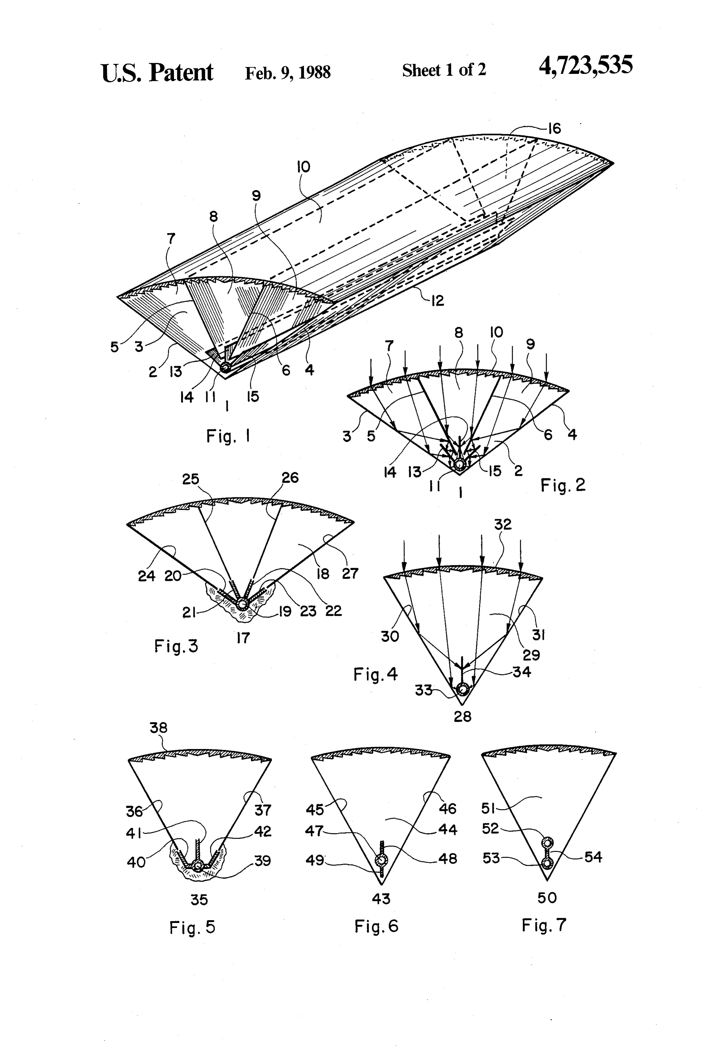
Every day the sun supplies an immense amount of ment FIG. 1 illustrates a perspective view of an embodi energy to the earth. Unfortunately, the intensity of the with Fresnelof the solar trap having compound light funnel solar energy falling on the earth is not high enough for lens cover.
most solar collectors to convert it into a useful form of shown in FIG. 1. a cross section of the solar trap FIG. 2 illustrates work in many demanding applications. The higher the FIG. 3 illustrates a cross section of another embodi intensity of the solar energy collected, the greater its ment of the solar trap having a compound light funnel applications are. The flat solar collectors widely used at with Fresnel lens cover.
the present time provide applications no better than 20 FIG. 4 illustrates a cross section of a further embodi heating dwelling spaces and hot water for domestic ment of the solar trap.
uses. The present day technology for collecting solar FIG. 5 illustrates a cross section of yet another em energy at a significantly elevated temperature is limited bodiment of the solar trap. to parabolic reflectors and focusing lenses, which are FIG. 6 illustrates a cross section of yet a further em expensive, complex and cumbersome technologies 25 bodiment of the solar trap. which are neither promising nor encouraging in terms FIG. 7 illustrates a cross section of still another em of their present status and their future potential. One of bodiment of the solar trap.
the most typical examples of solar energy application is FIG. 8 illustrates a cross section of still a further to use solar energy for air conditioning in the tropical embodiment of the solar trap.
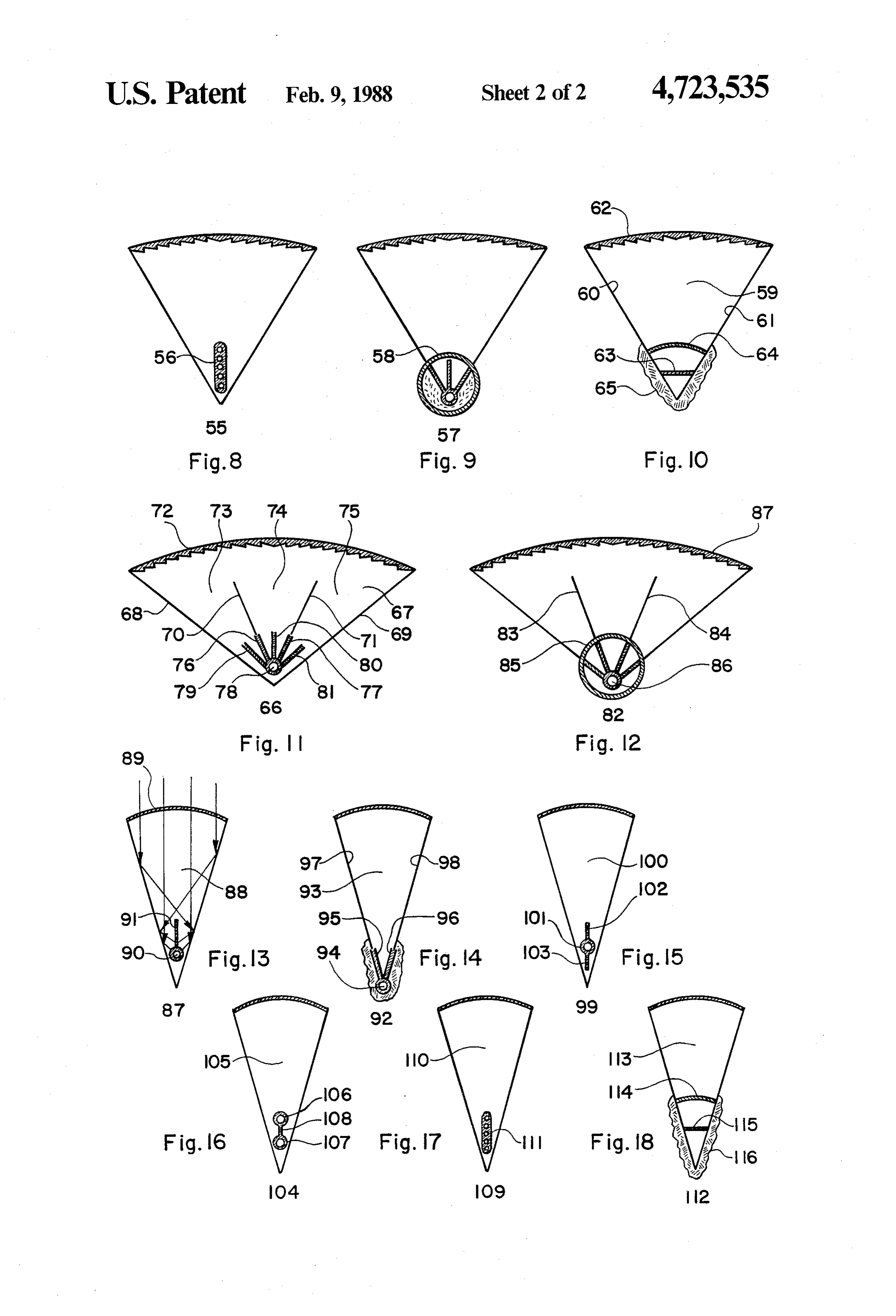
and subtropical regions where the expense of cooling in 30 FIG. 9 illustrates a cross section of additionally an summer time is far greater than the expense of heating in other embodiment of the solar trap. winter time. The use of solar energy for the cooling of FIG. 10 illustrates a cross section of additionally a living space is an extremely attractive concept in view further embodiment of the solar trap. that the greatest amount of cooling is required when the FIG. 11 illustrates a cross section of a solar trap em greatest amount of solar energy is available, which is ploying a wide angle light funnel.
combination virtually eliminates all necessity of storage FIG. 12 illustrates a cross section of another solar means for storing solar energy. The disappointing truth trap employing a wide angle light funnel. is that, at the present time, there is no inexpensive solar FIG. 13 illustrates a cross section of an embodiment collector available that is suitable for using solar energy of the simple solar trap having a simple transparent in air conditioning. 40 COVer.
SUMMARY OF THE INVENTION FIG. 14 illustrates a cross section of another embodi ment of the simple solar trap.
The primary object of the present invention is to FIG. 15 illustrates a cross section of a further embodi provide a concentrating solar collector that collects and ment of the simple solar trap.
delivers solar energy at a high intensity level. 45 FIG. 6 illustrates a cross section of yet another em Another object of the present invention is to provide bodiment of the simple solar trap.
a concentrating solar collector that needs not track the FIG. 17 illustrates a cross section of yet a further daily movement of the sun in nontracking installations embodiment of the simple solar trap.
and that tolerates a sizable tracking error in tracking FIG. 18 illustrates a cross section of still another installations. 50 embodiment of the simple solar trap. A further object of the present invention is to provide DESCRIPTION OF PREFERRED a concentrating solar collector that is inexpensive, EMBODIMENTS structurally simple and operationally trouble-free.
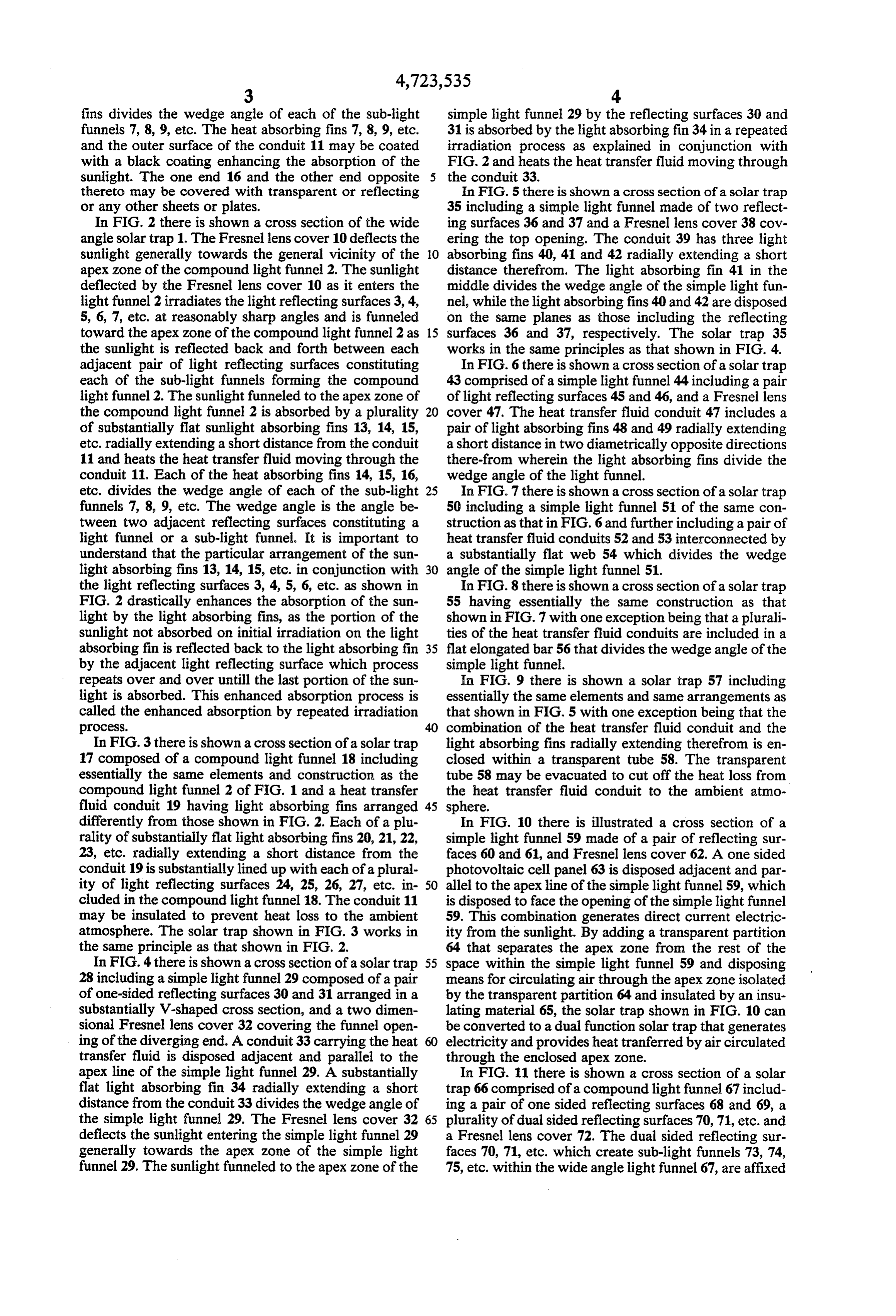
Yet another object of the present invention is to pro In FIG. 1 there is illustrated a perspective view of a vide a concentrating solar collector employing the sun- 55 section of a solar trap 1 composed of a compound light light funneling trough comprising of one or more pairs funnel 2 made of a pair of one sided reflecting surfaces of light-reflecting surfaces arranged in a substantially 3 and 4 arranged in a substantially V-shaped cross sec V-shaped cross section. tion and a pair of dual sided reflecting surfaces 5 and 6 Yet a further object of the present invention is to subdividing the compound light funnel made of the provide a concentrating solar collector comprising of 60 reflecting surfaces 3 and 4 into a plurality of sub-light one or more light funnels and one or more substantially funnels 7, 8, 9, etc. The opening at the diverging end of flat heat absorbing fins radially extending from one or the compound light funnel 2 is covered wtih a two more conduits disposed adjacent and parallel to the dimensional Fresnel lense cover 10. A conduit 11 for apex line of the light funnel wherein said conduit carries carrying a heat transfer fluid is disposed adjacent and a heat transfer fluid. 65 parallel to the apex line 12 of the compound light funnel Still another object of the present invention is to 2. The conduit 11 includes a plurality of substantially provide a two dimensional light funnel covered with a flat light absorbing fins 13, 14, 15, etc. radially extend two dimensional Fresnel lens cover. ing a short distance from the conduit 11, each of which
Page 5
fins divides the wedge angle of each of the sub-light simple light funnel 29 by the reflecting surfaces 30 and funnels 7, 8, 9, etc. The heat absorbing fins 7, 8, 9, etc. 31 is absorbed by the light absorbing fin 34 in a repeated and the outer surface of the conduit 11 may be coated irradiation process as explained in conjunction with with a black coating enhancing the absorption of the FIG. 2 and heats the heat transfer fluid moving through sunlight. The one end 16 and the other end opposite 5 the conduit 33.
thereto may be covered with transparent or reflecting In FIG. 5there is shown a cross section of a solar trap or any other sheets or plates. 35 including a simple light funnel made of two reflect In FIG. 2 there is shown a cross section of the wide ing surfaces 36 and 37 and a Fresnel lens cover 38 cov angle solar trap 1. The Fresnel lens cover 10 deflects the ering the top opening. The conduit 39 has three light sunlight generally towards the general vicinity of the O absorbing fins 40, 41 and 42 radially extending a short apex zone of the compound light funnel 2. The sunlight distance therefrom. The light absorbing fin 41 in the deflected by the Fresnel lens cover 10 as it enters the middle divides the wedge angle of the simple light fun light funnel 2 irradiates the light reflecting surfaces 3, 4, nel, while the light absorbing fins 40 and 42 are disposed 5, 6, 7, etc. at reasonably sharp angles and is funneled on the same planes as those including the reflecting toward the apex zone of the compound light funnel 2 as 15 surfaces 36 and 37, respectively. The solar trap 35 the sunlight is reflected back and forth between each works in the same principles as that shown in FIG. 4. adjacent pair of light reflecting surfaces constituting In FIG. 6there is shown a cross section of a solar trap each of the sub-light funnels forming the compound 43 comprised of a simple light funnel 44 including a pair light funnel 2. The sunlight funneled to the apex zone of of light reflecting surfaces 45 and 46, and a Fresnel lens the compound light funnel 2 is absorbed by a plurality cover 47. The heat transfer fluid conduit 47 includes a of substantially flat sunlight absorbing fins 13, 14, 15, pair of light absorbing fins 48 and 49 radially extending etc. radially extending a short distance from the conduit a short distance in two diametrically opposite directions 11 and heats the heat transfer fluid moving through the there-from wherein the light absorbing fins divide the conduit 11. Each of the heat absorbing fins 14, 15, 16, wedge angle of the light funnel.
etc. divides the wedge angle of each of the sub-light 25 In FIG.7 there is shown a cross section of a solar trap funnels 7, 8, 9, etc. The wedge angle is the angle be 50 including a simple light funnel 51 of the same con tween two adjacent reflecting surfaces constituting a struction as that in FIG. 6 and further including a pair of light funnel or a sub-light funnel. It is important to heat transfer fluid conduits 52 and 53 interconnected by understand that the particular arrangement of the sun a substantially flat web 54 which divides the wedge light absorbing fins 13, 14, 15, etc. in conjunction with 30 angle of the simple light funnel 51. the light reflecting surfaces 3, 4, 5, 6, etc. as shown in In FIG. 8 there is shown a cross section of a solar trap FIG. 2 drastically enhances the absorption of the sun 55 having essentially the same construction as that light by the light absorbing fins, as the portion of the shown in FIG. 7 with one exception being that a plurali sunlight not absorbed on initial irradiation on the light ties of the heat transfer fluid conduits are included in a absorbing fin is reflected back to the light absorbing fin 35 flat elongated bar 56 that divides the wedge angle of the by the adjacent light reflecting surface which process simple light funnel.
repeats over and over untill the last portion of the sun In FIG. 9 there is shown a solar trap 57 including light is absorbed. This enhanced absorption process is essentially the same elements and same arrangements as called the enhanced absorption by repeated irradiation that shown in FIG. 5 with one exception being that the process. combination of the heat transfer fluid conduit and the In FIG.3there is shown a cross section of a solar trap light absorbing fins radially extending therefrom is en 17 composed of a compound light funnel 18 including closed within a transparent tube 58. The transparent essentially the same elements and construction as the tube 58 may be evacuated to cut off the heat loss from compound light funnel 2 of FIG. 1 and a heat transfer the heat transfer fluid conduit to the ambient atmo fluid conduit 19 having light absorbing fins arranged 45 sphere.
differently from those shown in FIG. 2. Each of a plu In FIG. 10 there is illustrated a cross section of a rality of substantially flat light absorbing fins 20, 21, 22, simple light funnel 59 made of a pair of reflecting sur 23, etc. radially extending a short distance from the faces 60 and 61, and Fresnel lens cover 62. A one sided conduit 19 is substantially lined up with each of a plural photovoltaic cell panel 63 is disposed adjacent and par ity of light reflecting surfaces 24, 25, 26, 27, etc. in 50 allel to the apex line of the simple light funnel 59, which cluded in the compound light funnel 18. The conduit 11 is disposed to face the opening of the simple light funnel may be insulated to prevent heat loss to the ambient 59. This combination generates direct current electric atmosphere. The solar trap shown in FIG. 3 works in ity from the sunlight. By adding a transparent partition the same principle as that shown in FIG. 2. 64 that separates the apex zone from the rest of the In FIG. 4 there is shown across section of a solar trap 55 space within the simple light funnel 59 and disposing 28 including a simple light funnel 29 composed of a pair means for circulating air through the apex zone isolated of one-sided reflecting surfaces 30 and 31 arranged in a by the transparent partition 64 and insulated by an insu substantially V-shaped cross section, and a two dimen lating material 65, the solar trap shown in FIG. 10 can sional Fresnel lens cover 32 covering the funnel open be converted to a dual function solar trap that generates ing of the diverging end. A conduit 33 carrying the heat electricity and provides heat tranferred by air circulated transfer fluid is disposed adjacent and parallel to the through the enclosed apex zone.
apex line of the simple light funnel 29. A substantially In FIG. 11 there is shown a cross section of a solar flat light absorbing fin 34 radially extending a short trap 66 comprised of a compound light funnel 67 includ distance from the conduit 33 divides the wedge angle of ing a pair of one sided reflecting surfaces 68 and 69, a the simple light funnel 29. The Fresnel lens cover 32 65 plurality of dual sided reflecting surfaces 70, 71, etc. and deflects the sunlight entering the simple light funnel 29 a Fresnel lens cover 72. The dual sided reflecting sur generally towards the apex zone of the simple light faces 70, 71, etc. which create sub-light funnels 73, 74, funnel 29. The sunlight funneled to the apex zone of the 75, etc. within the wide angle light funnel 67, are affixed
Page 6
to the tips of the light absorbing fins 76, 77, etc. radially through the isolated apex zone of the plain light funnel extending a short distance from the heat transfer fluid 113 provides heat.
conduit 78, respectively, wherein the dual sided reflect While the principles of the present invention have ing surfaces 70, 71, etc extend radially just far enough to now been made clear by the illustrative embodiments, it funnel the sunlight deflected by the Fresnel lens cover 5 will be immediately obvious to those skilled in the art 72. The conduit 78 includes a further plurality of light that many modifications of the structure, arrangements, absorbing fins 79,80, 81, etc. radially extending a short elements, proportions and materials which are particu distance therefrom and dividing the wedge angles of the larly adapted to a certain working environment and sub-light funnel 73,74, 75, etc. respectively. operating condition in the practice of the invention are In FIG. 12 there is shown a cross section of a solar 10 possible without departing from those principles of the trap 82 having the same elements and the same arrange present invention.
ments as that shown in FIG. 3 with one exception being I claim:
that the dual sided reflecting surfaces 83 and 84 affixed 1. A solar trap for collecting solar energy at a concen to the transparent tube 85 extend radially just far trated level comprising:
enough to funnel the sunlight deflected by the Fresnel 15 (a) a compound light funnel including a pair of light lens cover 87. The combination of the heat transfer fluid reflecting substantially planar members arranged conduit 86 and the light absorbing fins radially extend into a trough having a substantially V-shaped cross ing therefrom is enclosed within the transparent tube section; and one or more dual sided light reflecting 85. The inside of the transparent tube 85 may be evacu planar members disposed radially intermediate said ated to prevent heat loss to the ambient atmosphere. 20 pair of light reflecting substantially planar mem In FIG. 13 there is shown a cross section of a solar bers, said one or more dual sided light reflecting trap 87 including a simple light funnel 88, a plain trans planar members dividing said substantially V parent cover 89 and a conduit 90 with a light absorbing shaped cross section comprising said pair of light fin 91. The plain light funnel 88 without the Fresnel lens reflecting substantially planar members into a plu cover must have a wedge angle less than thirty five 25 rality of sublight funnels having a substantially degrees in order to funnel the sunlight to the apex zone V-shaped cross section.
of a light funnel having a sizable depth. (b) a two dimensional Fresnel lens cover covering the In FIG. 14 there is illustrated a cross section of a solar opening of said compound light funnel, said open trap 92 including a plain light funnel 93 without a Fres ing being the open diverging end of said substan nel lens cover and a heat transfer fluid conduit 94 dis 30 tially V-shaped cross section of said compound posed at the apex line of the light funnel in a substan light funnel;
tially coaxial relationship. A pair of light absorbing fins (c) at least one conduit for carrying a heat transfer 95 and 96 extend radially a short distance from the fluid disposed substantially adjacent and substan conduit 94 in directions coinciding with the pair of the tially parallel to the apex line of said compound light reflecting surfaces 97 and 98 of the plain light 35 light funnel, said at least one conduit having at least funnel 93, respectively. The heat transfer fluid conduit two substantially flat light absorbing axial fins ex 94 and the light absorbing fins 95 and 96 are insulated. tending radially outward a short distance from said In FIG. 15 there is shown a cross section of a solar at least one conduit towards said Fresnel lens collector 99 comprised of a plain light funnel 100 and a cover; whereby said two dimensional Fresnel lens heat transfer fluid conduit 101 having a pair of light cover refracts the sunlight falling thereon gener absorbing fins 102 and 103 radially extending a short ally towards said apex zone, and said plurality of distance in two diametrically opposite directions there sublight funnels further aid in funneling the sun from and dividing the wedge angle of the plain light light towards said apex zone; each of said at least funnel 100. two light absorbing axial fins forming an acute In FIG.16there is illustrated a cross section of a solar 45 angle with respect to the nearest adjacent light collector 104 including a plain light funnel 105 and a absorbing axial fin, whereby a portion of radiation pair of conduits 106 and 107 interconnected by a light falling upon one of said at least two light absorbing absorbing web 108 that divides the wedge angle of the axial fins which is reflected rather than absorbed plain light funnel 105. will either be reflected back towards said light In FIG. 17 there is shown a cross section of a solar 50 absorbing axial fin by an adjacent light reflecting collector 109 including a plain light funnel 110 and a surface or will be absorbed or reflected back plurality of heat transfer fluid conduits disposed towards said light absorbing axial fin by an adja through a flat bar 111 dividing the wedge angle of the cent light absorbing surface. plain light funnel 110. 2. The combination as set forth in claim 1 wherein the In FIG. 18 there is shown a cross section of a dual 55 combination of said at least one conduit and said at least function solar collector 112 including a plain light fun two light absorbing axial fins is enclosed within a trans nel 113, a transparent partition 114 isolating the apex parent tube.
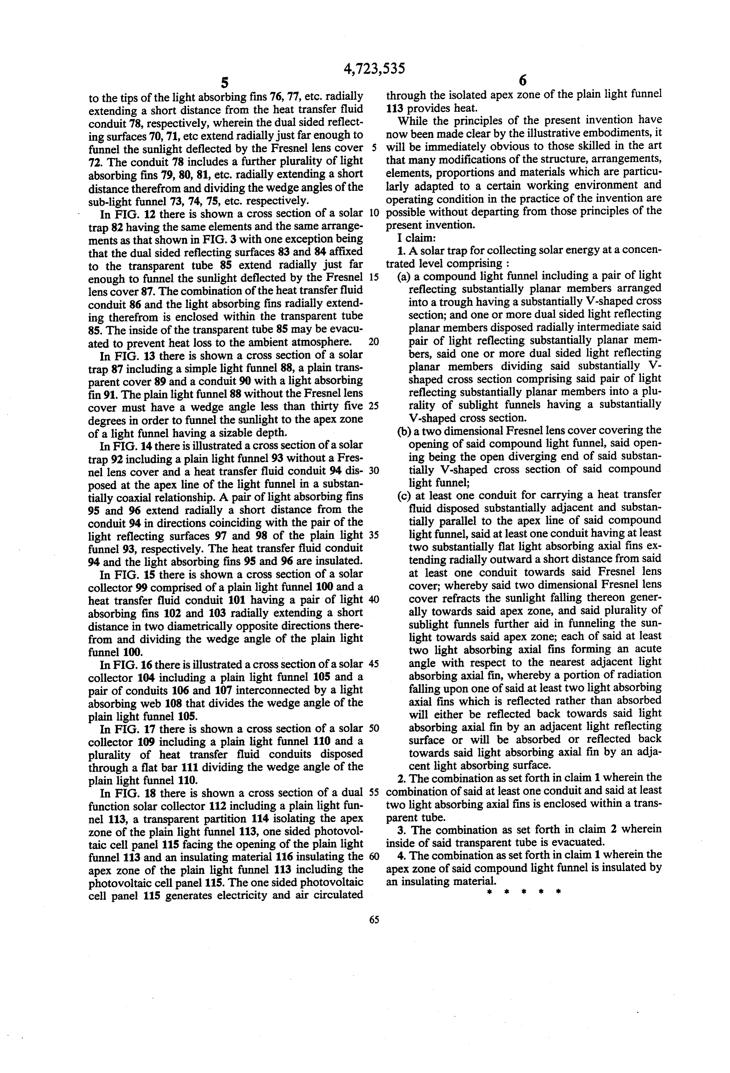
zone of the plain light funnel 113, one sided photovol 3. The combination as set forth in claim 2 wherein taic cell panel 115 facing the opening of the plain light inside of said transparent tube is evacuated. funnel 113 and an insulating material 116 insulating the 60 4. The combination as set forth in claim 1 wherein the apex zone of the plain light funnel 113 including the apex zone of said compound light funnel is insulated by photovoltaic cell panel 115. The one sided photovoltaic an insulating material.k sk sk k Ex cell panel 115 generates electricity and air circulated
Provenance
- Collection
- Cited prior art
- Original PDF
- patentimages.storage.googleapis.com →
- Filed
- 1984-10-09
- Pages
- 6
- Method
- pdftotext (the PDF's own text layer) + pdftoppm 300dpi page scans
- Source
- Google Patents bibliographic record
- Granted
- 1988-02-09
- Inventors
- Hyok S. Lew
- Transcribed from
- patentimages.storage.googleapis.com →