patent · US4307710
Solar energy collector system
29 December 1981
Page 1 — bibliographic record
United States Patent (19) 11) 4,307,710 Natter 45) Dec. 29, 1981
54 SOLAR ENERGY COLLECTOR SYSTEM 2429976 2/1980 France ................................ 26/440
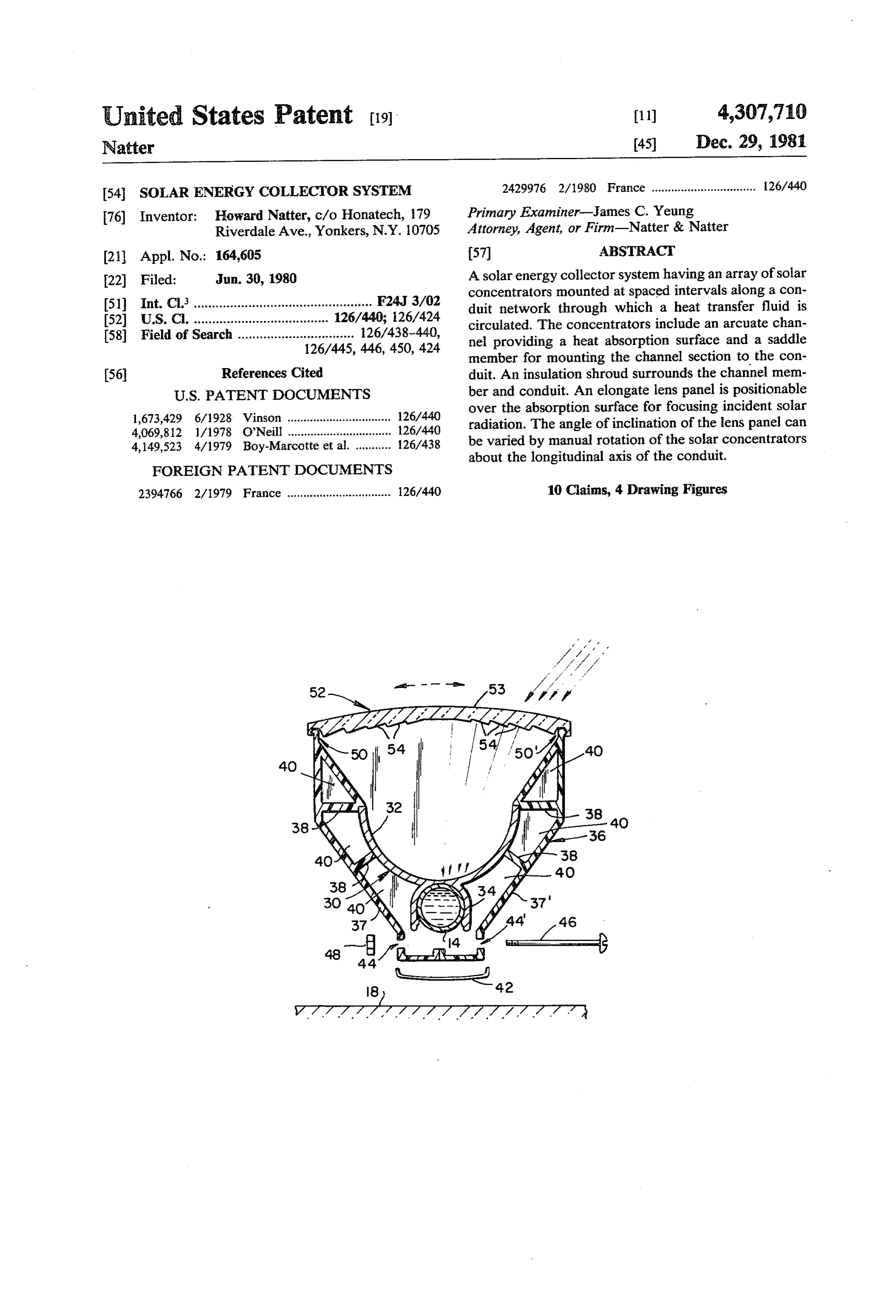
76) Inventor: Howard Natter, c/o Honatech, 179 Primary Examiner-James C. Yeung Riverdale Ave., Yonkers, N.Y. 10705 Attorney, Agent, or Firm-Natter & Natter 21 Appl. No.: 164,605 (57) ABSTRACT 22 Filed: Jun. 30, 1980 A solar energy collector system having an array of solar concentrators mounted at spaced intervals aiong a con 51 Int. Cl'................................................. F24, 3/02 duit network through which a heat transfer fluid is 52 U.S. C. ................ ... 126/440; 126/424 circulated. The concentrators include an arcuate chan 58) Field of Search ................................ 126/438-440, nei providing a heat absorption surface and a saddle
member for mounting the channel section to the con (56 References Cited duit. An insulation shroud surrounds the channel mem
1,673,429 6/1928 Winson ................................ 126/440 over the absorption surface for focusing incident solar 4,069,812 1/1978 O'Neill ..................... ... 126/440 radiation. The angle of inclination of the lens panel can 4,149,523 4/1979 Boy-Marcotte et al. ........... 126/438 be varied by manual rotation of the solar concentrators about the longitudinal axis of the conduit.
FOREIGN PATENT DOCUMENTS
23947.66 2/1979 France ................................ 126/440 10 Claims, 4 Drawing Figures
Page 2
Drawing sheet — no readable text.
Page 3
instant invention which also functions as a fastener for
SOLAR ENERGY COLLECTOR SYSTEM securing the insulation shroud.
It should be noted that a feature of this device is
BACKGROUND OF THE INVENTION directed to the method of fabrication wherein the solar concentrator is formed of extruded aluminum and the 1. Field of the Invention insulation shroud is a plastic such as polypropylene or This invention relates to a solar energy collector polycarbonate which can be extruded and thus provides system and especially to a system utilizing a distribution a relatively inexpensive, cost efficient, and lightweight network for circulating a liquid heat transfer and stor Structure.
age medium. 10 In view of the foregoing, it should be apparent that In particular, the solar apparatus of this invention is the present invention overcomes many of the shortcom concerned with an array of linear solar concentrators ings of the prior art devices and provides an improved adapted for conduit mounting to provide variable angu solar energy collector system which eliminates many of lar inclination settings for directing incident solar radia the problems of the prior art.
tion upon a curved energy absorption surface. 15
SUMMARY OF THE INVENTION
2. Description of the Prior Art
In view of the current energy crisis and the dramatic Briefly, the nature of the solar energy collector sys increase in utility costs, much attention has been di tem of this invention concerns a low cost, lightweight rected to alternate energy sources with considerable and easily constructed apparatus for concentrating solar emphasis upon solar technology. In response to this 20 radiation upon a matrix of copper tubing through which demand, solar energy systems were developed and in a heat transfer medium is circulated.
corporated into the basic construction of new homes, as A plurality of linear solar concentrators are posi well as in the retrofitting of existing heating systems. tioned over parallel connected segments of tubing. The Lack of widespread acceptance of many of the prior tubing is supported in spaced relationship from a roof art solar heating systems was due in part to economic 25 deck or other surface by support brackets. The solar considerations. Another problem with previous solar concentrators are assembled for seating upon the tub collectors was that they were not readily adaptable for ing.
compatible use in many homes and buildings. Some An elongate lens panel focuses the sun's rays upon a solar panels, for instance, were designed with absorber curved energy absorption surface of the concentrator. Heat is transmitted by conduction to the fluid within the plates and tubing which, when filled with water, added 30 tubing.
substantial weight to the roof deck. In addition to this of a bipartiteThe invention also encompasses the utilization live load, wind resistance and snow loading further cells around the insulation shroud for providing dead air increased the surcharge introduced by these solar col energy absorption surface and tubing. A feature of this invention relates to the design of the lectors. As a result, structural reinforcement of the roof 35 solar deck was frequently required. concentrator which combines an arcuate absorp Still other solar energy designs necessitated complex tion surface and saddle member for rotatable mounting upon the tubing. It should thus be apparent that, since installation beyond the ability of the average home the lens inclination angle can be varied, the solar con owner or required substantial initial investments and centrator can be mounted on different surface orienta constant or recurrent maintenance. Furthermore, the need for special tools, hardware and pipe fittings for 40 tions.
The lens panel includes a central section of uniform some of these solar devices presented disadvantages to thickness with an increasing cross sectional thickness their practical implementation and discouraged more progressively toward the opposite edges. This arrange frequent acceptance by consumers. ment tends to augment the focusing of light rays toward The solar energy collector system of this invention, in 45 the arcuate absorption surface.
contrast, utilizes linear solar concentrators which are In addition, the solar concentrator can be rotatably fabricated of aluminum and plastic materials and are displaced for focusing the sun's rays upon the absorp thus lightweight, can be readily handled for erection, tion surface to achieve maximum efficiency. Another and are comparatively simple to install without requir advancement incorporated in this device concerns the ing any special roof reinforcement or elaborate support 50 insulation shroud which is formed in two complemen structure. tary half sections and is secured in position around the It is further contemplated that the instant solar en absorption surface and tubing by metal spring clamps ergy collector can be manufactured and marketed either on the underside and by the lens panel along the upper preassembled or in kit form and will be fully compatible surface. In addition, screw fasteners can be used in place for retrofitting with currently used, hydronic heating 55 of or in addition to the metal spring clamps. systems. Furthermore, the solar concentrator of this Another feature of this invention is that it is suitable invention makes use of an arcuate absorption surface for packaging and sale in kit form for do-it-yourselfers. and adjustable mounting arrangement wherein the de Having thus summarized the invention it will be seen vice of this invention can be installed on a horizontal, that it is an object thereof to provide a solar energy inclined or vertical surface and can still make maximum collector system of the general character described utilization of the sun's rays for solar heating. herein which is not subject to the aforementioned disad An advantage of this invention over the prior art vantages.
relates to the design of the solar concentrator including Specifically, it is an object of this invention to pro the incorporation of a lightweight insulation shroud vide a solar energy collector system utilizing a circulat surrounding the absorption surface and conduit to mini 65 ing fluid within a conduit network and having an array mize heat loss. of independent linear solar concentrators supported at A further improvement over previous solar devices intervals along the conduit for thermal transference to concerns the use of a modified fresnel lens panel in the the fluid.
Page 4
A further object of this invention is to provide a solar purview of this invention upon horizontal or vertical energy collector system having a plurality of solar con surfaces.
centrators, each provided with an elongate lens panel With regard to this exemplary embodiment, a plural for concentrating solar radiation upon an arcuate en ity of independent solar concentrators 12 are mounted ergy absorption surface. in a parallel array upon a conduit network or tubular An additional object of the present invention is to matrix 14. A companion array of solar concentrators 12 provide a solar energy collector system wherein the is partially shown in F.G. 1, and it should be under solar concentrators are selectively rotatable about the stood that the number of solar concentrators 12, 12' in conduits for changing the angular inclination to maxi 10 any particular array and the number of companion ar mize incident solar radiation. rays can be varied in accordance with design require A still further object of this invention is to provide a ments.
solar energy collector system including a lightweight By way of background and for the purpose of further insulation shroud for minimizing heat losses during describing this invention, a conventional hydronic or thermal exchange with the circulating fluid. liquid type solar heating system utilizes water and an Yet another object of this invention is to provide a 15 antifreeze, e.g. ethylene glycol, as the working fluid solar energy collector system of the general character which is circulated through the tubular matrix 14. Typi described which is simple in construction, low in cost, cally, a pump (not shown) is employed for circulating reliable in use and well adapted for mass production the heat transfer medium to a heat exchange storage fabrication techniques. tank (not shown) and for recirculating cold water Other objects of the invention in part will be apparent 20 through the solar collector. In addition, auxiliary heat and in part will be pointed out hereinafter. sources, back-up systems, sensor circuits and control With these ends in view, the invention finds embodi units are used in conjunction with the solar heating ment in certain combinations of elements and arrange system as is known in the art. Referring again to the conduit network or tubular ments of parts by which the aforementioned objects and 25 matrix 14, it has been found that one-half inch I.D. certain other objects are hereinafter attained, all as fully described with reference to the accompanying draw copper tubing provides for satisfactory distribution for ings and the scope of which is more particularly pointed pattern havingfluid the working and can be arranged in a serpentine linear segments for accepting the solar out and indicated in the appended claims. concentrators 12 as shown in FIG. 1. In this connection BRIEF DESCRIPTION OF THE DRAWINGS 30 it should be noted that the copper tubing is compatible In the accompanying drawings in which is shown a able with standard plumbing hardware fittings and is adapt possible exemplary embodiment of the invention: for retrofitting existing hot water systems. The solar
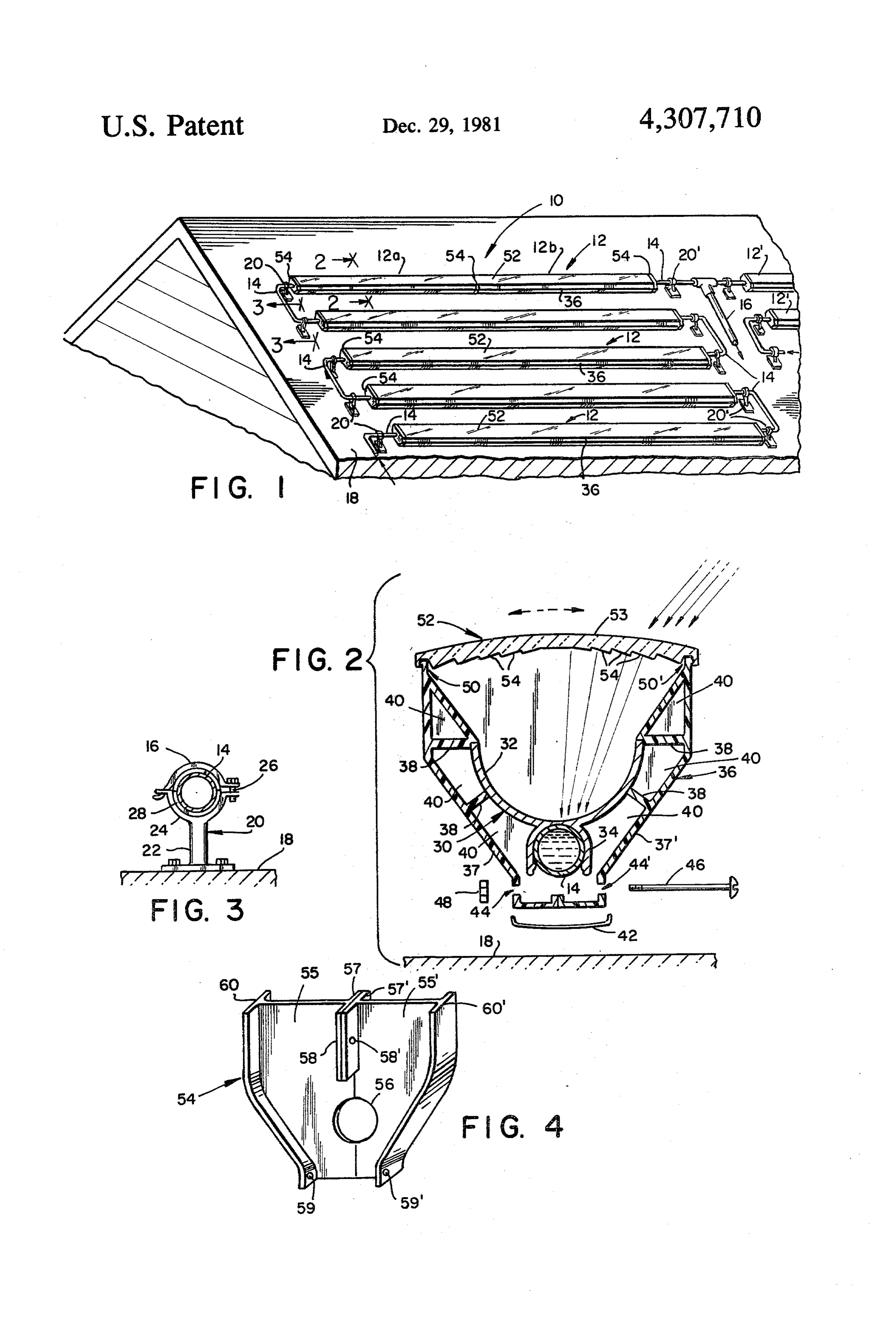
FIG. 1 is a perspective view of a solar energy collec common collector arrays further show the utilization of a tor system of this invention showing an array of linear 35 common drain line 16 and similarly can be fed from a manifold (not shown). The exposed curved solar concentrators on a pitched roof deck mounted segments of the tubular matrix 14 are wrapped or other upon a conduit network through which a heat transfer wise covered with a layer of insulation such as glass liquid is circulated in the directions typically indicated wool held in place by adhesive tape or the like. by the arrows; In regard to the installation of the solar system 10, the FIG. 2 is a sectional view to an enlarged scale of the 40 tubular matrix 14 is supported on linear solar concentrator taken substantially along line strategic locations at opposite ends aofroof a surface 18 at straight section 2-2 of FIG. 1 illustrating a channel member forming of tubing 14 by a pair of support brackets 20, 20' such as an arcuate heat absorption surface, a saddle member for illustrated in FIG. 3. The direction of the circulating seating on the conduit and an insulation shroud; the fluid is indicated by the arrows used in conjunction with refraction of incident light rays upon an elongate lens 45 the illustration of the tubular matrix 14. The bracket 20 panel for concentration upon the absorption surface is has a pedestal portion 22 and a flared cradle segment 24 denoted by the broken line arrows; in addition, the for receiving the tubing 14. a cover element 16 hingedly rotatable displacement of the solar concentrator about interfits with the cradle portion 24 at one end and is the longitudinal axis of the conduit is indicated by the provided with a bolt and lock nut 26 at the opposite end double headed arrow; 50 for adjustably tightening over the tubing 14. In addi FIG. 3 is a sectional view to an enlarged scale taken tion, an insulation sleeve 28 is provided both along the substantially along line 3-3 of FIG. 1 illustrating a cover element 16 and the cradle portion 24 for reducing bracket fixed to the roof deck including an insulation heat loss through the tubing 14. It should be noted that sleeve and adjustable clamp for supporting the conduit the aforementioned clamping arrangement for securing with displacement compensation for expansion and 55 the tubing 14 is intended to provide required tolerances contraction; and by the loosening of the bolt and wing nut 26 as needed FIG. 4 is a perspective view to a slightly smaller scale for expansion and length extension upon heating or of a closure plate for the solar concentrator such as resultant contraction upon cooling of the tubing 14. In illustrated in FIG. 2. one preferred arrangement one of the two support 60 brackets 20, 20' for each straight length of tubing 14 can
DESCRIPTION OF THE PREFERRED
EMBODIMENT be preloosened, however later adjustments can also be made as needed.
Referring now in detail to the drawings, the reference The solar concentrator 12 will now be described in numeral 10 denotes generally a solar energy collector further detail with particular reference to FIG. 2. A system of this invention. The solar system 10 is illus 65 typical solar concentrator 12 includes a channel mem trated in FIG. 1 in a typical installation upon a sloped ber 30 having an arcuate absorption surface 32 and a roof deck of a dwelling house. As previously indicated, U-shaped saddle portion 34 for snug engagement with the solar system 10 is also adaptable for use within the the tubing 14. The channel member 30 can be formed of
Page 5
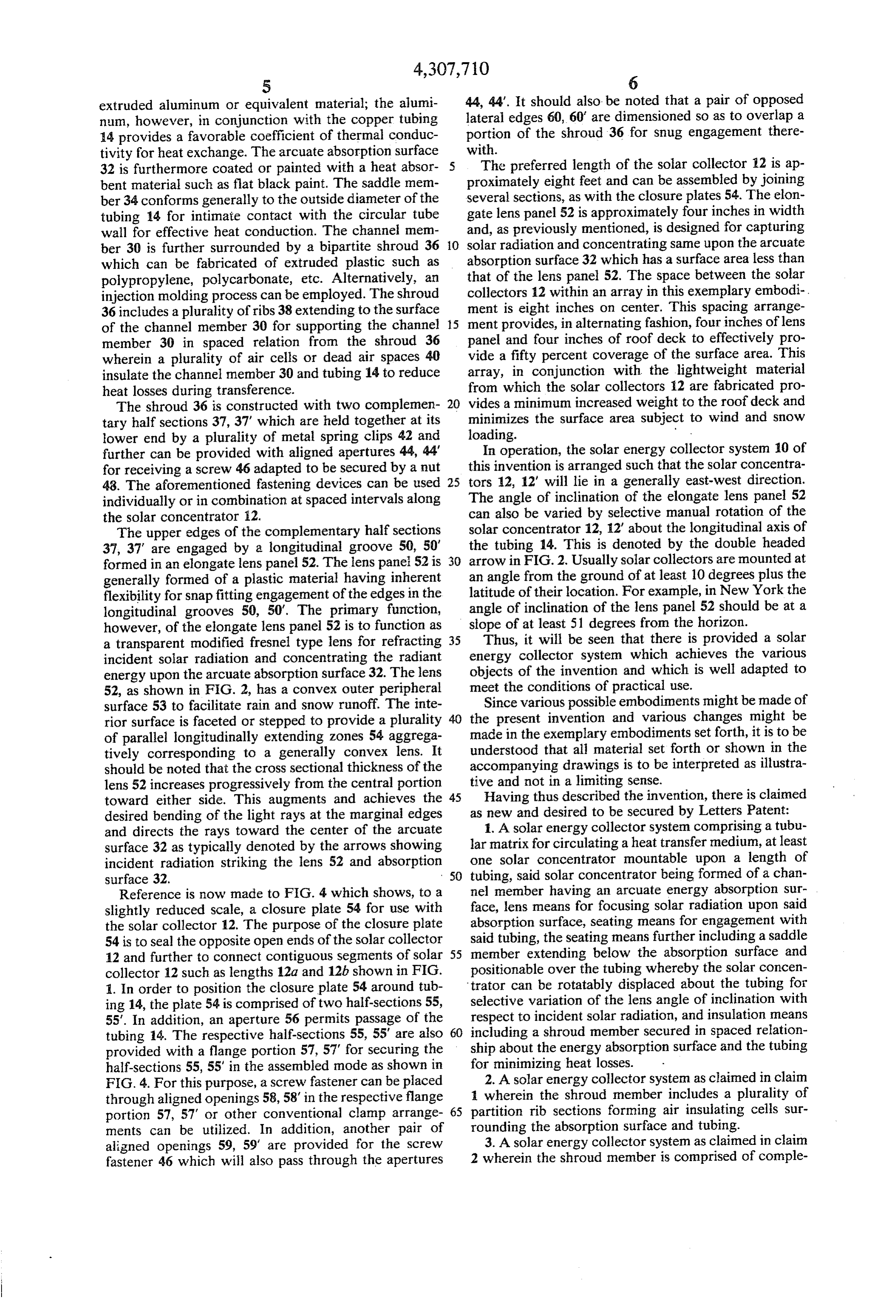
extruded aluminum or equivalent material; the alumi 44, 44'. It should also be noted that a pair of opposed num, however, in conjunction with the copper tubing lateral edges 60, 60' are dimensioned so as to overlap a 14 provides a favorable coefficient of thermal conduc portion of the shroud 36 for snug engagement there tivity for heat exchange. The arcuate absorption surface with.
32 is furthermore coated or painted with a heat absor The preferred length of the solar collector 12 is ap bent material such as flat black paint. The saddle mem proximately eight feet and can be assembled by joining ber 34 conforms generally to the outside diameter of the several sections, as with the closure plates 54. The elon tubing 14 for intimate contact with the circular tube gate lens panel 52 is approximately four inches in width wall for effective heat conduction. The channel mem and, as previously mentioned, is designed for capturing ber 30 is further surrounded by a bipartite shroud 36 O solar radiation and concentrating same upon the arcuate which can be fabricated of extruded plastic such as absorption surface 32 which has a surface area less than polypropylene, polycarbonate, etc. Alternatively, an that of the lens panel 52. The space between the solar injection molding process can be employed. The shroud collectors 12 within an array in this exemplary embodi 36 includes a plurality of ribs 38 extending to the surface ment is eight inches on center. This spacing arrange of the channel member 30 for supporting the channel 15 ment provides, in alternating fashion, four inches of lens member 30 in spaced relation from the shroud 36 panel and four inches of roof deck to effectively pro wherein a plurality of air cells or dead air spaces 40 vide a fifty percent coverage of the surface area. This insulate the channel member 30 and tubing 14 to reduce array, in conjunction with the lightweight material heat losses during transference. from which the solar collectors 12 are fabricated pro The shroud 36 is constructed with two complemen 20 vides a minimum increased weight to the roof deck and tary half sections 37, 37' which are held together at its minimizes the surface area subject to wind and snow lower end by a plurality of metal spring clips 42 and loading.
further can be provided with aligned apertures 44, 44 In operation, the solar energy collector system 10 of for receiving a screw 46 adapted to be secured by a nut this invention is arranged such that the solar concentra 48. The aforementioned fastening devices can be used 25 tors 12, 12" will lie in a generally east-west direction. individually or in combination at spaced intervals along The angle of inclination of the elongate lens panel 52 the solar concentrator 12. can also be varied by selective manual rotation of the The upper edges of the complementary half sections solar concentrator 12, 12' about the longitudinal axis of 37, 37" are engaged by a longitudinal groove 50, 50' the tubing 14. This is denoted by the double headed formed in an elongate lens panel 52. The lens panei 52 is 30 arrow in FIG. 2. Usually solar collectors are mounted at generally formed of a plastic material having inherent an angle from the ground of at least 10 degrees plus the flexibility for snap fitting engagement of the edges in the latitude of their location. For example, in New York the longitudinal grooves 50, 50'. The primary function, angle of inclination of the lens panel 52 should be at a however, of the elongate lens panel 52 is to function as slope of at least 51 degrees from the horizon. a transparent modified fresnel type lens for refracting 35 Thus, it will be seen that there is provided a solar incident solar radiation and concentrating the radiant energy collector system which achieves the various energy upon the arcuate absorption surface 32. The lens objects of the invention and which is well adapted to 52, as shown in FIG. 2, has a convex outer peripheral meet the conditions of practical use.
surface 53 to facilitate rain and snow runoff. The inte Since various possible embodiments might be made of rior surface is faceted or stepped to provide a plurality the present invention and various changes might be of parallel longitudinally extending zones 54 aggrega made in the exemplary embodiments set forth, it is to be tively corresponding to a generally convex lens. It understood that all material set forth or shown in the should be noted that the cross sectional thickness of the accompanying drawings is to be interpreted as illustra lens 52 increases progressively from the central portion tive and not in a limiting sense.
toward either side. This augments and achieves the 45 Having thus described the invention, there is claimed desired bending of the light rays at the marginal edges as new and desired to be secured by Letters Patent: and directs the rays toward the center of the arcuate 1. A solar energy collector system comprising a tubu surface 32 as typically denoted by the arrows showing lar matrix for circulating a heat transfer medium, at least incident radiation striking the lens 52 and absorption one solar concentrator mountable upon a length of surface 32. 50 tubing, said solar concentrator being formed of a chan Reference is now made to FIG. 4 which shows, to a nel member having an arcuate energy absorption sur slightly reduced scale, a closure plate 54 for use with face, lens means for focusing solar radiation upon said the solar collector 12. The purpose of the closure plate absorption surface, seating means for engagement with 54 is to seal the opposite open ends of the solar collector said tubing, the seating means further including a saddle 12 and further to connect contiguous segments of solar 55 member extending below the absorption surface and collector 12 such as lengths 12a and 12b shown in FIG. positionable over the tubing whereby the solar concen 1. In order to position the closure plate 54 around tub trator can be rotatably displaced about the tubing for ing 14, the plate 54 is comprised of two half-sections 55, selective variation of the lens angle of inclination with 55'. In addition, an aperture 56 permits passage of the respect to incident solar radiation, and insulation means tubing 14. The respective half-sections 55, 55' are also 60 including a shroud member secured in spaced relation provided with a flange portion 57, 57" for securing the ship about the energy absorption surface and the tubing half-sections 55, 55' in the assembled mode as shown in for minimizing heat losses.
FIG. 4. For this purpose, a screw fastener can be placed 2. A solar energy collector system as claimed in claim through aligned openings 58, 58' in the respective flange 1 wherein the shroud member includes a plurality of portion 57, 57 or other conventional clamp arrange 65 partition rib sections forming air insulating cells sur ments can be utilized. In addition, another pair of rounding the absorption surface and tubing. aligned openings 59, 59' are provided for the screw 3. A solar energy collector system as claimed in claim fastener 46 which will also pass through the apertures 2 wherein the shroud member is comprised of comple
Page 6
mentary components adapted for securement along oppositely to the arcuate absorption surface and con their upper edges by interfitting with the lens means and forming generally to the outside diameter of the tubing along their lower confronting edges by removable fas for snug fitting engagement therewith. tener means. 7. A solar energy collector system as claimed in claim 4. A solar energy collector system as claimed in claim 1 further including a plurality of brackets for supporting 3 wherein the lens means includes an elongate lens the tubular matrix, said brackets being releasably adjust panel, said lens panel defining longitudinal grooves able to compensate for tubular expansion and length extending along opposed margins, said grooves being extension upon heating.
adapted to receive the upper edges of the shroud com 8. A solar energy collector system as claimed in claim ponents whereby the lens panel is positioned in con O 7 wherein the bracket further includes a cradle segment fronting relationship with respect to the energy absorp and a hingedly interfitting cover element which is ad tion surface. justably tightenable over the tubing. 5. A solar energy collector system as claimed in claim 9. A solar energy collector system as claimed in claim 4 wherein the lens panel has a cross-sectional thickness 1 further including a closure plate, said closure plate which increases progressively from a central portion 15 being adapted for interfitting engagement with the op toward either side of the panel for refracting solar rays posite open ends of the shroud member. on the absorption surface. 10. A solar energy collector system as claimed in 6. A solar energy collector system as claimed in claim claim 9 wherein the closure plate is further adapted for 1 wherein the saddle member is formed integrally with securing contiguous aligned shroud members. the channel member as a U-shaped portion opening 20 sk :k k ck sk
Provenance
- Collection
- Cited prior art
- Original PDF
- patentimages.storage.googleapis.com →
- Filed
- 1980-06-30
- Pages
- 6
- Method
- pdftotext (the PDF's own text layer) + pdftoppm 300dpi page scans
- Source
- Google Patents bibliographic record
- Granted
- 1981-12-29
- Inventors
- Howard Natter
- Transcribed from
- patentimages.storage.googleapis.com →