patent · US20120011851A1
Solar Heat Collector
19 January 2012
Page 1 — bibliographic record
(19) United States (12) Patent Application Publication (10) Pub. No.: US 2012/0011851 A1
LieVre (43) Pub. Date: Jan. 19, 2012 (54) SOLAR HEAT COLLECTOR (52) U.S. Cl. ...................................... 60/641.15; 126/698 (76) Inventor: Laurier Lievre, Mundare (CA) (21) Appl. No.: 13/183,111 (57) ABSTRACT (22) Filed: Jul. 14, 2011 A Solar heat collector includes a housing defining an insulated Related U.S. Application Data chamber extending from a focusing lens at a solar receiving end to a target glass at a target end forming a boundary wall (60) Provisional application No. 61/364,064, filed on Jul. between the insulated chamber and a target chamber receiv 14, 2010. ing a heat transfer fluid therein. A target object is Supported in O O the target chamber at the focal point of the focusing lens So as Publication Classification to be surrounded by the heat transfer fluid. In a preferred (51) Int. Cl. embodiment a heat engine is supported on the target end of F03G 6/06 (2006.01) the housing Such that the target object and heat transfer fluid F24, 2/08 (2006.01) are the heat Source of the heat engine.
Page 2
Drawing sheet — no readable text.
Page 3
Drawing sheet — no readable text.
Page 4
Drawing sheet — no readable text.
Page 5
Drawing sheet — no readable text.
Page 6
Drawing sheet — no readable text.
Page 7
US 2012/001 1851 A1 Jan. 19, 2012
SOLAR HEAT COLLECTOR 0010 the target glass forming a boundary wall between the insulated chamber and a target chamber which is arranged to receive a heat transfer fluid therein; and 0001. This application claims the benefit under 35 U.S.C. 0011 a target object supported in the target chamber sub 119(e) of U.S. provisional application Ser. No. 61/364,064, stantially at the focal point of the focusing lens So as to be filed Jul. 14, 2010. arranged to be surrounded by the heat transfer fluid. 0012. The solar collector of the present invention provides
FIELD OF THE INVENTION an improved boiler compared to prior art solar boilers in that 0002 The present invention relates to a solar heat collector the actual boiler chamber locating the heat transfer fluid including a focusing lens for focusing Solar rays from the Sun therein is very small and concentrated at the focal point of a onto a target object Surrounded by a heat exchanging fluid. single focussing lens. By separating the target chamber and the focussing lens with an insulated chamber therebetween,
BACKGROUND heat losses from the boiler are minimized. The minimal size of the target chamber adjacent the focal point of the focussing 0003. It is known to use the rays from the Sun to heat a fluid lens permits very high temperatures to be achieved for opti for various uses including the heating of buildings or per mal efficiency in energy recovery at the outlet of the boiler. forming various forms of useful work. Examples of solar 0013 The improved configuration for heating a fluid sur boilers are described in U.S. Pat. Nos. 4,057,048 by Maine; rounding the target object is also well Suited for using the 4,246,886 by Sitzlar; 4,056,093 by Barger; and 5,191,875 by heated fluid as the heat source or working fluid in a heat Edling et al. Typically in the prior art, the heat transfer fluid is engine Such as a Stirling engine which is operable between a located in a large chamber Such that the boiler area is vary heat source and a cold sink. When there is provided a steering large having potential for large convective losses. Further mechanism arranged to steer movement of the housing rela more, the large areas have limited capacity to heat the tive to a position of the Sun, preferably the heat engine is exchanger fluid to very elevated temperatures due to the Supported on the housing for steering movement together potential for convective losses. with the housing Such that the heat engine is arranged to be 0004. In other instances, energy is captured from the sun Supported within a shadow of the housing relative to the Sun. by focussing rays onto a solar cell. U.S. Pat. No. 6,881.893 by 0014 Preferably a diameter of the target glass is smaller Cobert discloses one example of a Solar collector in commu than a diameter of the focusing lens and a distance between nication with a solar cell in which a focussing lens together the target glass and the focusing lens is greater than a radius of with a reflective parabolic chamber direct sunlight towards the focusing lens Such that the target lens is near in diameter the solar cell. No mechanism is provided for cooling the cell to a diameter of the focused Solar rays arranged to be received however and accordingly the amount of concentration of the therethrough.
solar rays must be limited to prevent overheating. Even when 0015 The housing walls are preferably tapered linearly the cell does not overheat, the lack of any mechanism to inwardly towards one another from the receiving end to the capture the heating results in a considerable waste of energy target end Such that the housing walls are arranged to be in the form of wasted heat. Substantially parallel to focused solar rays adjacent a perim 0005 U.S. Pat. No. 6,653,551 by Chen discloses a further eter of the focusing lens.
example of a Solar cell in combination with a series of lenses 0016. The target glass preferably comprises a high tem or optical concentrators to direct concentrated Solar rays onto perature resistant fused silica glass. a solar cell in communication with heat transfer fluid. The 0017. In some embodiments, the target object comprises a optical concentrators are in direct contact with the chamber plurality of conductive filaments bundled together such that locating the heat transfer fluid Surrounding the Solar cell so the heat exchange fluid is arranged to pass between the con that there is still potential for considerable conductive heat ductive filaments.
losses through the optical concentrator. Furthermore, the 0018 Preferably an insulating glass also spans parallel to overall combination of lenses is particularly complex so that the focusing lens at the receiving end of the housing Such that it would be particularly difficult to vary the scale of the solar the insulated chamber is fully surrounded by the insulating collector for different applications. glass, the target glass and the housing walls spanning between
SUMMARY OF THE INVENTION
the insulating glass and the target glass.
0019 Preferably the focusing lens and the target glass are 0006. According to one aspect of the invention there is in sealing engagement with the housing walls about a full provided a solar heat collector arranged for collecting Solar perimeter thereof.
rays from the Sun, the Solar heat collector comprising: 0020. In a preferred embodiment, the housing is supported 0007 a housing comprising housing walls Surrounding an on a Supporting structure comprising: insulated chamber spanning in a longitudinal direction 0021 a central Support arranged to Support the target end between a receiving end and a target end of the housing: of the housing thereon for pivotal movement thereon such that 0008 a focusing lens spanning Substantially perpendicu the housing is pivotal relative to the central Support about a larly to the longitudinal direction at the receiving end of the Vertical steering axis and about a horizontal tilt axis adjacent housing and arranged to focus Solar rays inwardly towards a to the target end of the housing: focal point adjacent the target end of the housing: 0022 a circular track supported about the vertical steering 0009 a target glass spanning Substantially perpendicu axis of the central Support;
larly to the longitudinal direction at the target end of the 0023 a carriage member supported for movement about housing adjacent the focal point of the focusing lens, the the circular track;
target glass being arranged to receive focused solar rays from 0024 an extendible frame assembly connected between the focusing lens therethrough; the carriage member and the housing at a location spaced
Page 8
US 2012/001 1851 A1 Jan. 19, 2012
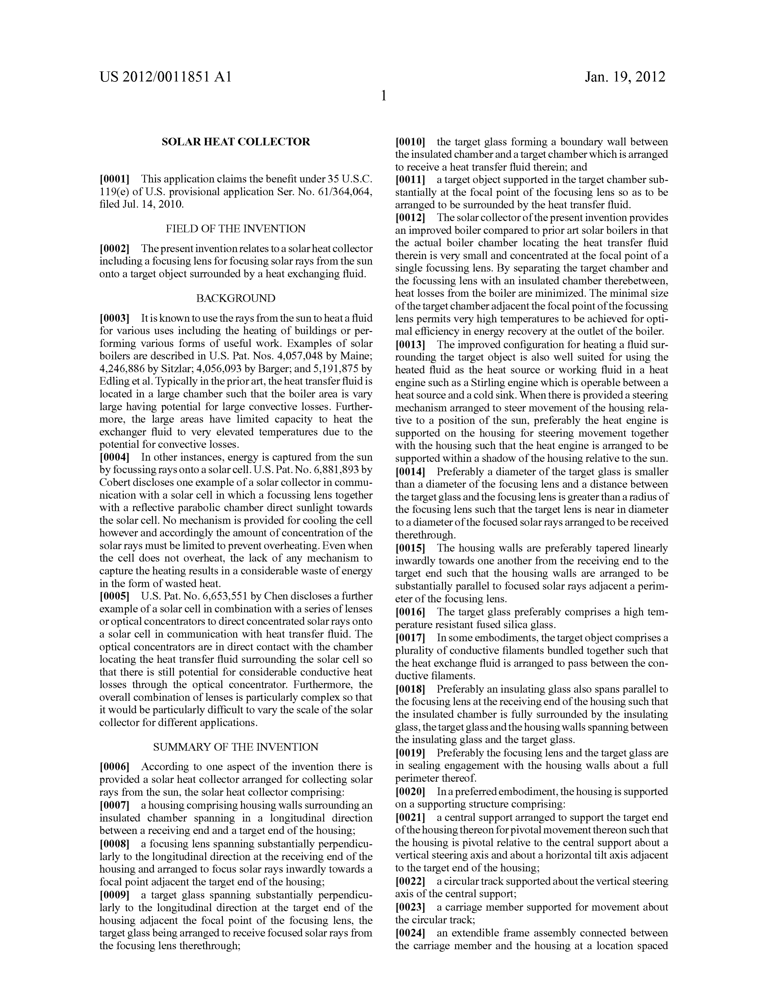
from the target end of the housing towards the receiving end 0036 the target glass forming a boundary wall between of the housing so as to support the receiving end of the the insulated chamber and a target chamber which is arranged housing on the carriage member for movement together along to receive a heat transfer fluid therein; the circular track about the vertical steering axis; and 0037 a target object supported in the target chamber sub 0.025 a steering mechanism comprising a first actuator stantially at the focal point of the focusing lens So as to be adapted to control movement of the housing about the Vertical arranged to be surrounded by the heat transfer fluid; steering axis and a second actuator adapted to control move 0038 an inlet in communication with the target chamber ment of the housing about the horizontal tilt axis such that the So as to be arranged to Supply heat transfer fluid to the target steering mechanism is adapted to steer the receiving end of chamber; and the housing towards the Sun Such that the longitudinal direc 0039 an outlet in communication with the target chamber tion of the housing remains aligned with the Solar rays from to receive a heated flow of heat transfer fluid from the target the Sun.
chamber;
0026. According to another embodiment of the invention, 0040 the outlet being configured such that the heated flow the target object may comprise a solar cell arranged to gen is passively driven by boiling of the fluid in the target cham erate an electrical current in response to the Solar rays ber.
focussed thereon.
0027. The target object may alternatively comprise a heat 0041 According to a further aspect of the present inven tion there is provided a solar heat collector arranged for absorbent material. In this instance there may be provided an collecting Solar rays from the Sun, the Solar heat collector inlet in communication with the target chamber so as to be comprising:
arranged to Supply heat transfer fluid to the target chamber 0042 a housing comprising housing walls Surrounding an and an outlet in communication with the target chamber to insulated chamber spanning in a longitudinal direction receive a heated flow of heat transfer fluid from the target between a receiving end and a target end of the housing: chamber. In this instance, the target object also preferably 0043 a focusing lens spanning Substantially perpendicu comprises a plurality of conductive filaments tangled together
Such that the heat exchange fluid is arranged to pass there larly to the longitudinal direction at the receiving end of the through between the conductive filaments. housing and arranged to focus Solar rays inwardly towards a 0028. The outlet may be configured such that the heated focal point adjacent the target end of the housing: flow is passively driven by boiling of the fluid in the target 0044 a target glass spanning Substantially perpendicu chamber. Moreparticularly, the outlet may comprise an outlet larly to the longitudinal direction and arranged to receive tube connected to a top end of the target chamber so as to be focused Solar rays from the focusing lens therethrough; arranged to receive pockets of heat transfer fluid in a vapour 0045 the target glass forming a boundary wall between state rising through the outlet tube in a manner which induces the insulated chamber and a target chamber which is arranged an upward flow of heat transfer fluid in a liquid state therewith to receive a heat transfer fluid therein; and to an auxiliary holding tank separate from the target chamber. 0046 a target object supported in the target chamber sub 0029. The inlet may comprise an inlet passage in open stantially at the focal point of the focusing lens So as to be communication between a Supply tank and a bottom end of arranged to be surrounded by the heat transfer fluid; the target chamber, the Supply tank including a float valve 0047 the target object comprising a solar cell arranged to arranged to maintain a level of heat transfer fluid in the Supply generate an electrical current in response to the Solar rays tank Substantially at an elevation of a top end of the target focussed thereon.
chamber. 0048. Some embodiments of the invention will now be 0030 Arranging the target object to comprise a conductive described in conjunction with the accompanying drawings in member fully surrounded by heat transfer fluid optimally which:
transfers heat to the heat transfer fluid.
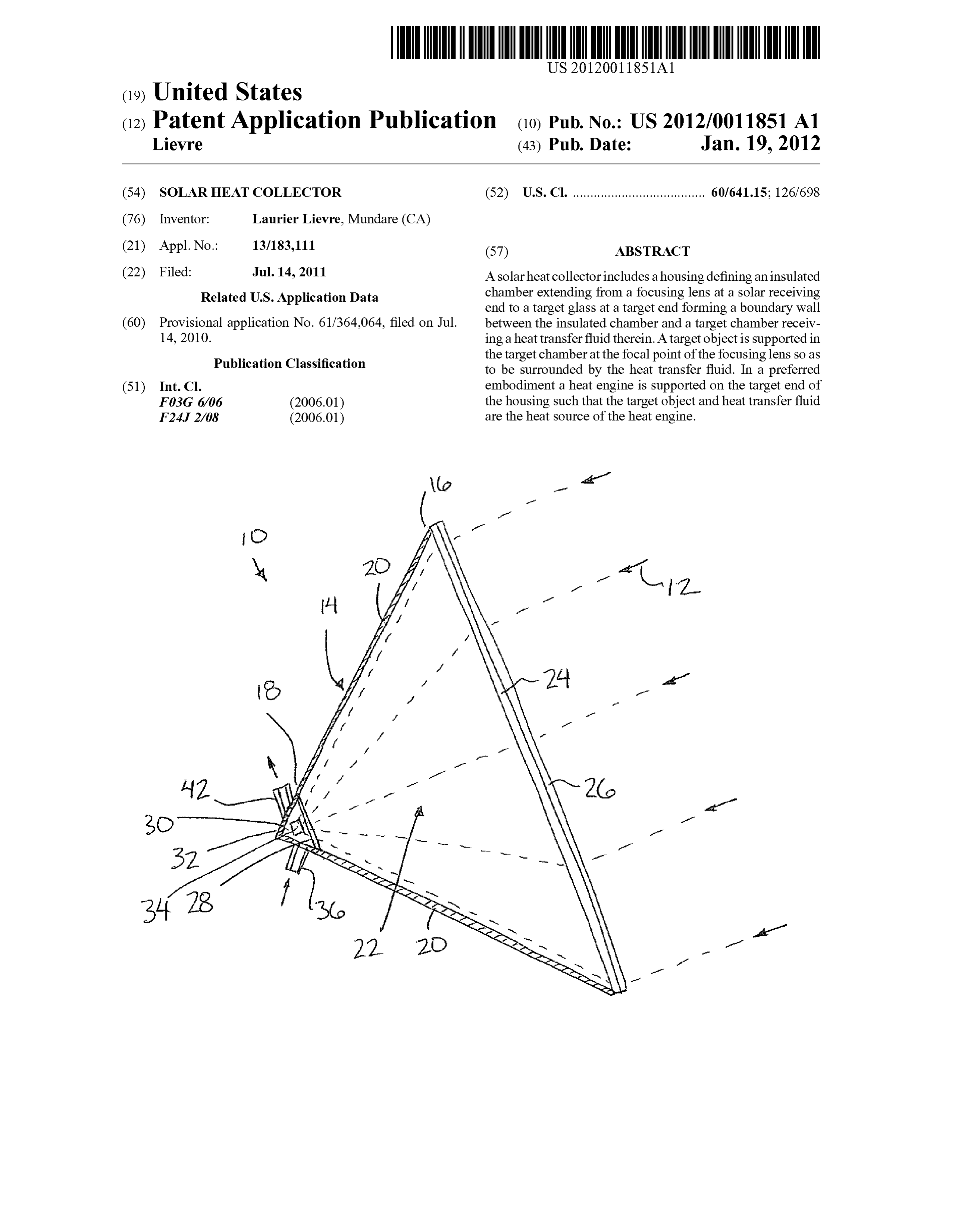
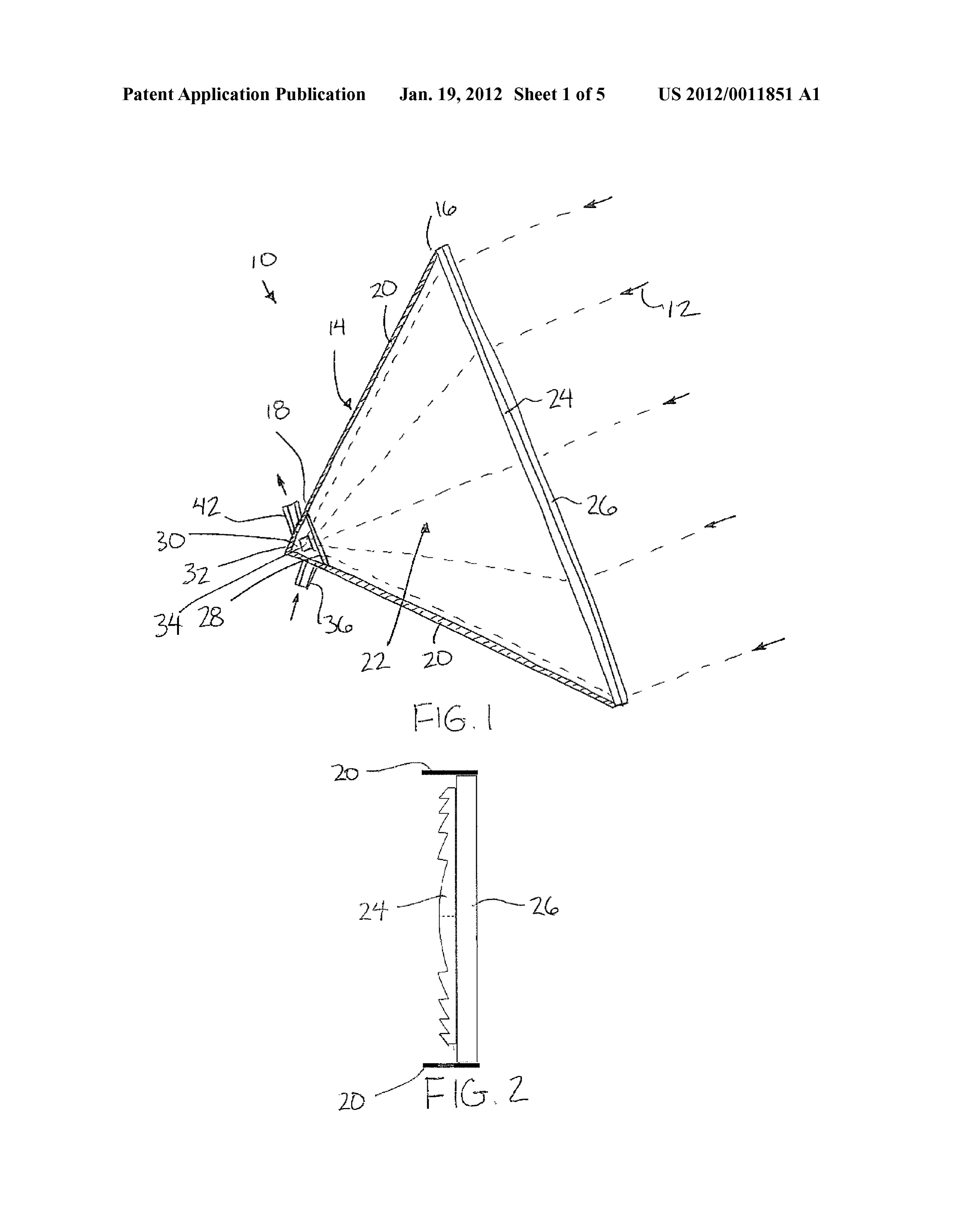
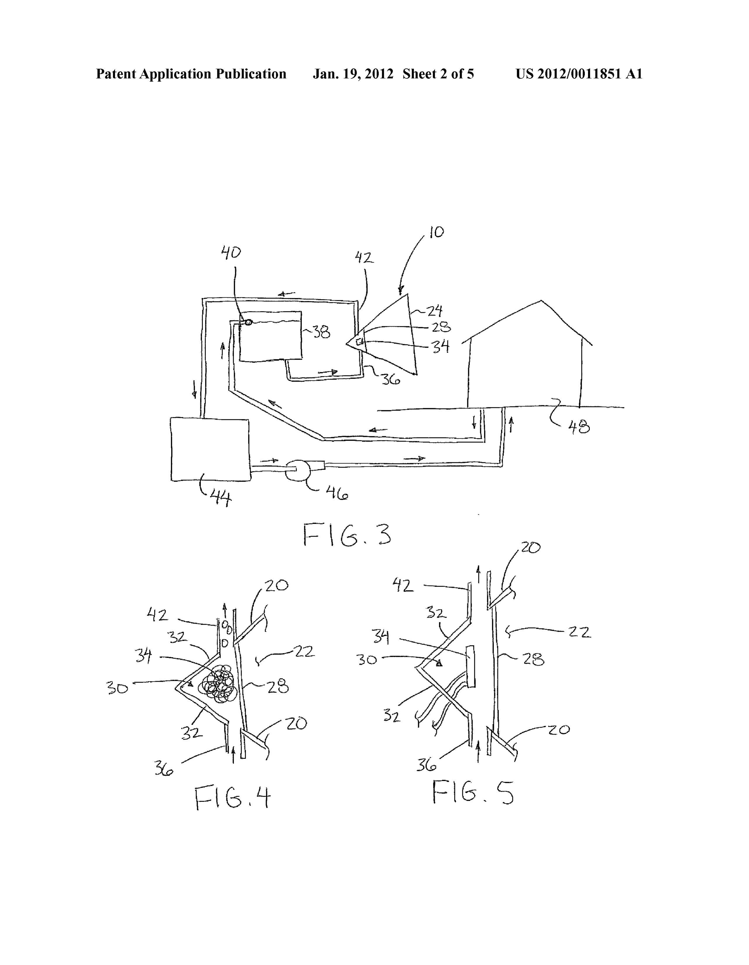
0031. Alternatively, when the target object comprises a BRIEF DESCRIPTION OF THE DRAWINGS Solar cell, the configuration of the target chamber provides efficient cooling to the Solar cell with a minimum of losses in 0049 FIG. 1 is sectional side elevational view of the solar conveying the Solar rays from the focussing lens to the Solar heat collector;
cell due to the insulated chamber spanning the majority of the 0050 FIG. 2 is a sectional view of the focusing lens of the housing between the focussing lens and the target glass adja solar heat collector;
cent the focal point of the focussing lens. 0051 FIG. 3 is a schematic representation of an operating 0032. According to another aspect of the present invention system associated with the solar heat collector of FIG. 1; there is provided a Solar heat collector arranged for collecting
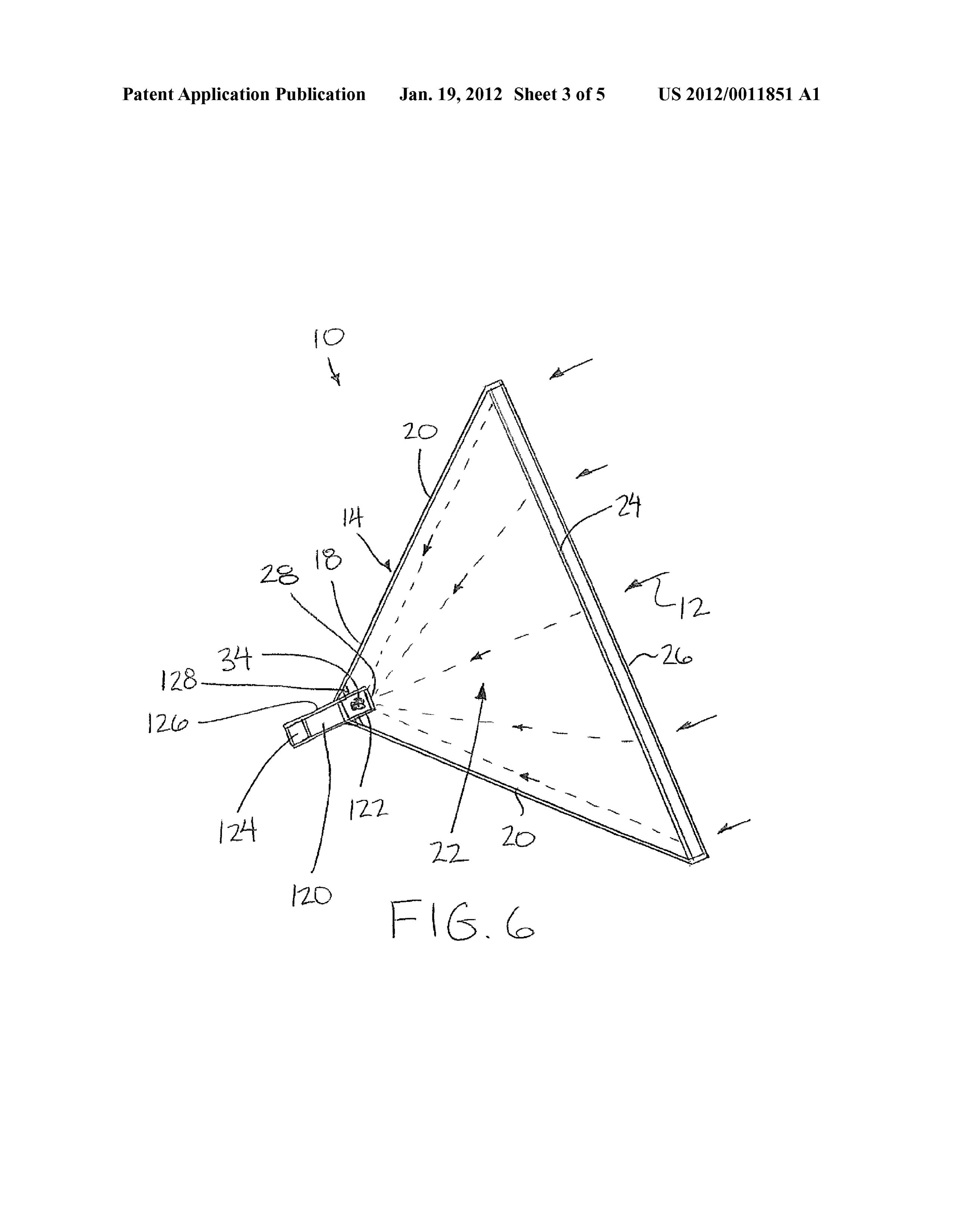
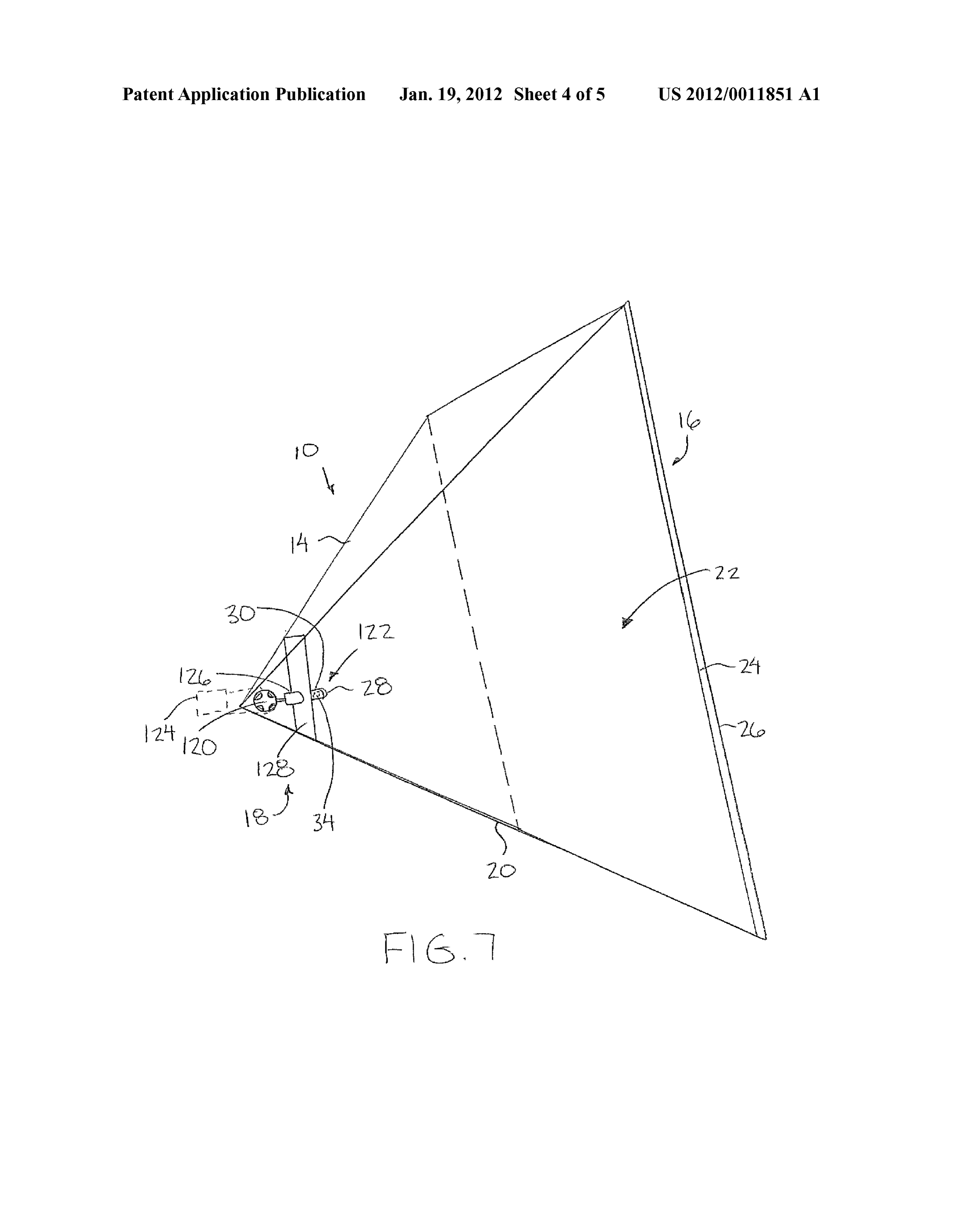
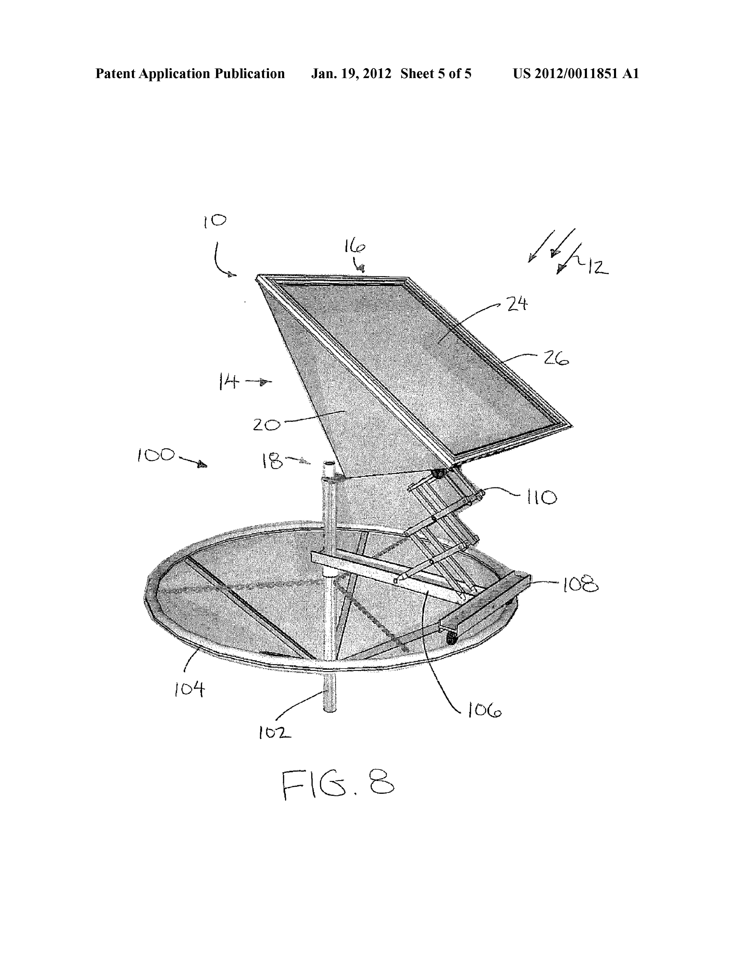
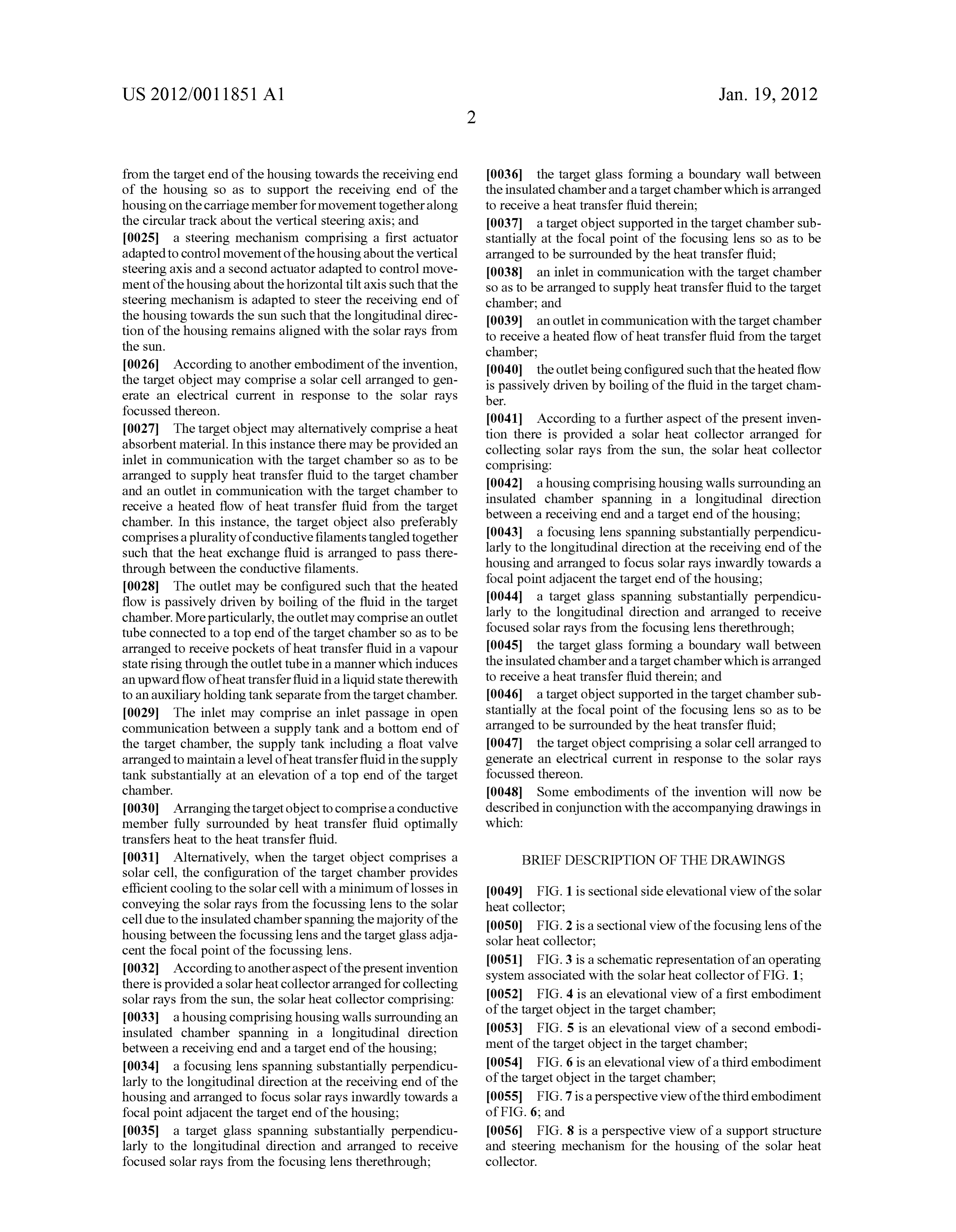
Solar rays from the Sun, the Solar heat collector comprising: 0.052 FIG. 4 is an elevational view of a first embodiment 0033 a housing comprising housing walls Surrounding an of the target object in the target chamber, insulated chamber spanning in a longitudinal direction 0053 FIG. 5 is an elevational view of a second embodi between a receiving end and a target end of the housing: ment of the target object in the target chamber; 0034 a focusing lens spanning Substantially perpendicu 0054 FIG. 6 is an elevational view of a third embodiment larly to the longitudinal direction at the receiving end of the of the target object in the target chamber, housing and arranged to focus Solar rays inwardly towards a 0055 FIG. 7 is a perspective view of the third embodiment focal point adjacent the target end of the housing: of FIG. 6; and 0035 a target glass spanning Substantially perpendicu 0056 FIG. 8 is a perspective view of a support structure larly to the longitudinal direction and arranged to receive and steering mechanism for the housing of the Solar heat focused Solar rays from the focusing lens therethrough; collector.
Page 9
US 2012/001 1851 A1 Jan. 19, 2012
0057. In the drawings like characters of reference indicate than the focussing lens and is near in diameter to the diameter corresponding parts in the different figures. of the focussed rays at the cross section of the rays perpen dicular to the longitudinal direction at the target glass loca
DETAILED DESCRIPTION tion. By arranging the target glass 28 to be slightly larger than 0058 Referring to the accompanying figures there is illus the corresponding focal plane of the focussed rays passing trated a solar heat collector generally indicated by reference therethrough, substantially all of the focussed rays are numeral 10. The collector 10 is arranged to collect solar rays directed through the target glass into an adjacent target cham 12 from the sun to convert the solar rays into a usable form of ber. The target glass 28 is uniform in thickness So as to be energy for performing useful work. non-magnifying, transparent and clear and so as to form a 0059 Although various embodiments are disclosed in the boundary wall between the insulating chamber and the target accompanying specification, the common features of the vari chamber. Due to the proximity of the target glass to the focal ous embodiments will first be described. point of the focussing lens, the target glass is spaced apart 0060. The collector 10 includes a housing 14 extending from the focussing lens by a distance which is resultingly generally in a longitudinal direction from a receiving end 16 much greater than a radius of the focussing lens. The target to a target end 18. The housing is arranged to be aligned Such glass is formed of a high temperature resistant material, for that the longitudinal direction is generally aligned with the example a fused silica glass.
direction of the solar rays which are received into the receiv 0066. The housing walls 20 are continuous beyond the ing end 16 of the housing. The collector serves to direct the target glass so as to project linearly from the focussing lens rays inwardly towards the target end 18 of the housing. past the target glass to a common apex forming the other end 0061 The housing includes insulated housing walls 20 of the target chamber 30 opposite the target glass. The portion which surround an insulated chamber 22 of the housing. The of the housing walls extending beyond the target glass to the walls Surround the chamber 22 on all sides spanning between apex thus define side walls 32 of the target chamber which the opposing receiving and target ends of the housing. The together with the boundary wall formed by the target glass walls are tapered linearly inwardly towards one another from fully surround the target chamber. The focal point of the the receiving end to the target end. The walls may be any one focussing lens is arranged to be generally central within the of various shapes in cross section. When square in cross target chamber.
section the resulting walls are generally pyramidal in shape 0067. A target object 34 is centrally located in the target between the receiving end and the target end. Similarly when chamber to be located at the focal point of the concentrated the walls are round in cross section, the housing is generally rays focussed by the lens 24 while being fully surrounded by conical in shape between the receiving end and the target end. a Surrounding heat transfer fluid filling the target chamber, for 0062. A focusing lens 24 is mounted to fully span the example water or glycol. The target object 34 occupies a receiving end 16 of the housing perpendicularly to the longi majority of the volume of the target chamber with the sur tudinal direction. The focussing lens is similar in shape to the rounding heat transfer fluid being arranged to capture Sub cross section of the housing walls So that the housing walls are stantially all of the heat from the target object. joined to the focusing lens about the full perimeter thereof. 0068. As shown in FIG. 8, a suitable supporting structure 0063. In the illustrated embodiment, the focusing lens 24 Supports the collector housing thereon Such that the housing comprises a Fresnel lens arranged to focus the incoming Solar can be reoriented in the direction of the Sun's rays. In particu rays in the longitudinal direction inwardly towards a common lara steering mechanism includes suitable sensors for sensing focal point at the target end 18 of the housing. The rays are the orientation of the Sun together with actuators responsive focused inwardly by the Fresnel lens 24 such that the rays to the sensors to steer the receiving end of the housing to face adjacent the perimeter of the lens are redirected inwardly towards the Sun and align the longitudinal direction of the Substantially at the same angle as the slope of the housing housing with the direction of the Sun's rays. walls 20 tapering inwardly from the receiving end to the target 0069. The supporting structure 100 includes a central Sup end. The boundary rays focussed by the lens 24 are thus port 102 in the form of a vertical post. A circular track 104 is Substantially parallel to the housing walls. Supported by a plurality of spokes extending radially outward 0064. An insulating glass 26 is mounted parallel and adja from the post such that the track is coaxial about the central cent to the focussing lens to also fully span the receiving end post spaced above the ground. A radial arm 106 is pivotally of the housing perpendicularly to the longitudinal direction. Supported at an inner end on the post and extends radially The insulating glass and the focussing lens are sealed by a outward to an outer end coupled to a carriage member 108 suitable resilient gasket about the full perimeter of the insult Supported on rollers for rolling movement along the circular ing glass to join the insulating glass to the housing walls Such track 104 as the inner end of the radial arm 106 is pivoted that the insulating glass forms a boundary of the insulated about the vertical axis of the central post 102. chamber 22 of the housing at the receiving end thereof. The 0070 An extendable frame 110 is supported on the radial focussing lens 24 is thus spaced inwardly towards the target arm of the carriage member to extend generally upward to an end of the housing relative to the insulating glass. Alterna upper end Supporting a respective portion of the housing of tively, the insulating glass may be integrally formed with the the solar collector thereon. The extendable frame comprises a focussing lens which is in turn similarly sealed about a full plurality of inter-connected links which are pivotal relative to perimeter, using a similar sealing gasket. one another in a Scissor lift configuration between a retracted 0065. A target glass 28 spans across the target end of the position and an extended position in which the overall height housing adjacent the focal point of the focussing lens 24 at a of the extendible frame 110 is greater than the retracted posi location spaced slightly inwardly from the focal point tion.
towards the receiving end of the housing. The diameter of the 0071. The housing is supported on the support structure target glass 28 corresponds to the diameter of the housing at Such that the target end of the housing is pivotally coupled to the target end Such that the target glass is Smaller in diameter the central support 102 spaced above the circular track for
Page 10
US 2012/001 1851 A1 Jan. 19, 2012
pivotal movement of the housing about a vertical steering axis barrier 128 opposite the receiving end of the housing is sub about the central support as well as about a horizontal tilt axis stantially isolated from the solar rays and the heat collected in adjacent to the target end of the housing Substantially at the the target chamber at the first end of the engine housing. vertical axis of the central support. The extendible frame 110 (0076 Turning now to the embodiments of FIGS. 4 and 5, Supports rollers at the upper end thereof for rolling engage the heat transfer fluid in this instance is circulated by a suit ment with a corresponding lowermost one of the side walls of able operating system. In particular the system includes an the housing between the receiving and target ends. The rollers inlet 36 in the form of an inlet tube in open communication of the extendible frame thus engage the housing at a location with the bottom side of the target chamber as well as being in spaced radially outward from the vertical axis adjacent the open communication with a Supply tank 38. The open com target end towards or adjacent to the receiving end of the munication between the Supply tank 38 and the target cham housing. ber results in the fluid level between the tank and the target 0072 The steering mechanism includes a first actuator chamber being maintained Substantially equal. The Supply adapted to control pivotal movement of the housing relative to tank 38 is in turn supplied by re-circulated fluid which is the central Support about the vertical steering axis thereof as pumped therein. A float valve 40 maintains the level in the well as a second actuator adapted to control movement of the Supply tank, and accordingly also in the target chamber, at the housing about the horizontal tilt axis by controlling the exten height of the top of the target chamber. sion and retraction of the extendible frame 110. By control 0077. The operating system further comprises an outlet 42 ling the first and second actuators, the steering mechanism is in the form of an outlet tube in communication with the top of adapted to steer the receiving end of the housing towards the the target chamber to receive a heated flow of heat transfer Sun Such that the longitudinal direction of the housing fluid overflowing from the target chamber which is then remains aligned with the Solar rays of the Sun. directed into an auxiliary holding tank 44. The holding tank 0073 Turning now to FIGS. 6 and 7, according to a pre 44 is an insulated tank, for example Supported below ground. ferred embodiment, the target object in this instance acts as In some instances however the tank may be Supported above the heat source of a heat engine 120. The heat engine com ground where it is impractical or there is no advantage to prises a free piston-type Stirling engine for operation between Supporting the tank below ground.
aheat source 122 at a first end of a housing of the heat engine 0078. As the fluid in the target chamber is heated by the assembly and a cold sink 124 at an opposing second end of the solar rays heating the target object, the heated flow of fluid housing of the engine. The heat engine comprises a free piston exits through the outlet. The heated flow is driven by arrang operated on a Sterling cycle coupled to a linear generator ing the diameter of the outlet tube to be small enough that within a common housing of the engine assembly. For pockets of heat transfer fluid which are heated into a vapour example, one Suitable heat engine is commercially available state which rise upwardly through the outlet tube drive a under the trademark name SunCatcherTM by Stirling Engine surrounding flow of heat transfer fluid in a liquid state Systems Inc. located in Scottsdale, Ariz. together therewith upwardly for overflowing into the over 0074 The housing of the heat engine assembly 120 is flow holding tank 44. The heated flow is thus passively driven mounted on the housing of the Solar collector at the target end by boiling of the fluid in the target chamber without requiring thereof such that the heat engine is moveable together with an auxiliary pump between the target chamber and the hold the housing relative to the support structure 100, while the ing tank 44.
housing undergoes steering movement controlled by the first 0079. In some instances, check valves may be required at and second actuators noted above. By orienting the receiving the inlet and outlet to ensure that flow is directed through the end of the collector housing towards the Sun, the steering outlet 42 as the heat transfer fluid heats up and pressure builds mechanism ensures that the heat engine assembly, and par within the target chamber to passively drive the flow direction ticularly the cold sink 124 thereof remain in the shadow of the to the outlet. The use of check valves is particularly suited collector housing when Supported at the target end of the when operating the Solar collector near the equator as the lens housing. and flow direction through the target chamber may be near 0075. At the first end of the engine housing, the target horizontal in orientation in this instance. Various emergency chamber of the solar collector is defined by walls of the and safety control are also provided to prevent problems with engine housing 126 and the target glass 28 spanning the first overheating and to vent excess pressure if either the heat end of the engine housing. Similarly to the embodiment of exceeds or the pressure exceeds prescribed limits of the con FIG.4, described below, the target object includes a mass of trols.
conductive filaments 34 surrounded by heat transfer fluid in 0080 Turning now more particularly to the embodiment the target chamber such that the fluid can freely pass between of the target object as shown in FIG.4, the target object in this the filaments bundled together. The conductive filaments are instance comprises a mass of heat absorbent material. More located at the focal point of the focusing lens 24 to be heated particularly in the illustrated embodiment, the target object directly by Solar rays which in turn heats the Surrounding heat comprises stainless steel wool or like materials comprising a transfer fluid which may be arranged to exchange heat with plurality of conductive filaments which are tangled together the working fluid of the heat engine 120 or may comprise the either as a matted mass or as a woven mass of filaments working fluid of the engine directly. The target glass is sealed through which the heat transfer fluid is arranged to pass. The with respect to the Surrounding walls of the engine housing open coils of conductive filaments heat up as the concentrated 126. The insulated barrier 128 spans generally perpendicu solar rays are directed thereon at the focal point of the focus larly to the longitudinal direction of the collector housing sing lens with the heat being Subsequently transferred to the radially outward from the walls of the engine housing 126 to Surrounding heat transfer fluid flowing therethrough. the Surrounding walls of the collector housing in sealed com I0081. As shown in FIG. 5, according to another embodi munication therebetween Such that the remaining portion of ment of the target object 34, the target object comprises a the engine housing 126 extending rearward from the insulated Solar cell which is arranged to generate an electrical current in
Page 11
US 2012/001 1851 A1 Jan. 19, 2012
response to the Solar rays being focussed thereon. Various a focusing lens spanning Substantially perpendicularly to commercially available types of solar cells can be used for the longitudinal direction at the receiving end of the effectively generating an electric current directly. In this housing and arranged to focus Solar rays inwardly instance, the heat transfer fluid can similarly be overflowed towards a focal point adjacent the target end of the hous into a holding tank for use in producing other useful energy. 1ng 0082 In either instance of the embodiments of FIG. 4 or 5. a target glass spanning Substantially perpendicularly to the the heated fluid in the holding tank can be pumped by a longitudinal direction at the target end of the housing suitable pump 46 to be directed to perform useful work such adjacent the focal point of the focusing lens, the target as heating a building 48 and the like. Once the heat has been glass being arranged to receive focused Solar rays from extracted from the heat transfer fluid at the building 48, the the focusing lens therethrough; fluid can be re-circulated back under pressure to the supply the target glass forming a boundary wall between the insu tank which supplies the fluid to the target chamber of the lated chamber and a target chamber which is arranged to collector. receive a heat transfer fluid therein; and 0083. As described herein, the sunlight passes through the a target object Supported in the target chamber Substan window which consists of insulating glass followed by a tially at the focal point of the focusing lens so as to be Fresnel lens, an insulated air chamber, then through the target arranged to be surrounded by the heat transfer fluid. glass. Generally the Fresnel lens and insulating glass are the 2. The solar heat collector according to claim 1 wherein a same height and width. As Sunlight passes through the win diameter of the target glass is Smaller than a diameter of the dow, it then passes through insulated air chamber. All edges of focusing lens.
the window are sealed to prevent air leaks. The shape and size 3. The solar heat collector according to claim 1 wherein a of the housing coincides with the shape of the window. If the distance between the target glass and the focusing lens is window is round, the housing is cone shaped. If the window is greater than a radius of the focusing lens. square or rectangular, the housing is a four sided pyramidal 4. The solar heat collector according to claim 1 wherein the shape. This provides optimal use of the Suns energy as it is target lens is near in diameter to a diameter of the focused focused onto the target which is located precisely at the focal Solar rays arranged to be received therethrough. point of the lens. The target glass is round in shape, optically 5. The solar heat collector according to claim 1 wherein the clear, slightly larger than the size of the magnified Sunlight housing walls are tapered linearly inwardly towards one spot, and can withstand the high temperatures produced by another from the receiving end to the target end. magnified sunlight. Sealed to and behind the target, is the 6. The solar heat collector according to claim 1 wherein the conical heat exchanger tank. It has hose connectors located at housing walls are tapered inwardly towards one another from the top and at the bottom directly behind the target. Inside the the receiving end to the target end Such that the housing walls heat exchanger tank, liquid (e.g. water) is fed into the bottom are arranged to be substantially parallel to focused Solar rays inlet, heated by the Sun in the heat exchanger tank using a adjacent a perimeter of the focusing lens. conductor (stainless steel wool) as an internal heating ele 7. The solar heat collector according to claim 1 wherein the ment. The water percolates out the top outlet. The window is target glass comprises a high temperature resistant fused fastened to the housing and there is a sealing gasket around silica glass.
the outer edge to prevent air leaks between the housing and 8. The solar heat collector according to claim 1 wherein the the window. The target and parts are made of materials that target object comprises a plurality of conductive filaments can withstand high temperatures. Water is fed into the heat bundled together such that the heat exchange fluid is arranged exchanger tank using a process like a toilet holding tank. The to pass between the conductive filaments. water holding tank sits a level that keeps the heat exchanger 9. The solar heat collector according to claim 1 further tank full. As water percolates out of the heat exchanger tank, comprising an insulating glass spanning parallel to the focus it is replenished by the water holding tank and it is kept at the ing lens at the receiving end of the housing, the insulated full level using a float valve. The solar collector is designed to chamber being fully Surrounded by the insulating glass, the track and follow the sun. When the water reaches boiling target glass and the housing walls spanning between the insu temperature, it flows into the storage tank where the water is lating glass and the target glass. then pumped into a home and used for heating purposes. 10. The solar heat collector according to claim 1 wherein Water is circulated from the storage tank back to the solar the focusing lens and the target glass are in sealing engage collector while the sun is out. There are many other uses for ment with the housing walls about a full perimeter thereof. the invention like water purification, steam power generation, 11. The solar heat collector according to claim 1 further and others.
comprising a heat engine operable between a heat source and 0084. Since various modifications can be made in my a cold sink, the heat transfer fluid comprising the heat Source invention as herein above described, and many apparently of the heat engine.
widely different embodiments of same made within the spirit 12. The solar heat collector according to claim 1 wherein and scope of the claims without department from Such spirit there is provided a steering mechanism arranged to steer and scope, it is intended that all matter contained in the movement of the housing relative to a position of the Sun and accompanying specification shall be interpreted as illustrative wherein the heat engine is Supported on the housing for Steer only and not in a limiting sense. ing movement together with the housing Such that the heat engine is arranged to be supported within a shadow of the 1. A Solar heat collector arranged for collecting Solar rays housing relative to the Sun.
from the Sun, the Solar heat collector comprising: 13. The solar heat collector according to claim 1 wherein a housing comprising housing walls Surrounding an insu the target object comprising a solar cell arranged to generate lated chamber spanning in a longitudinal direction an electrical current in response to the Solar rays focussed between a receiving end and a target end of the housing: thereon.
Page 12
US 2012/001 1851 A1 Jan. 19, 2012
14. The solar heat collector according to claim 1 wherein wherein there is provided an inlet in communication with the the housing is Supported on a Supporting structure compris target chamber so as to be arranged to Supply heat transfer ing: fluid to the target chamber and an outlet in communication a central Support arranged to Support the target end of the with the target chamber to receive a heated flow of heat housing thereon for pivotal movement thereon Such that transfer fluid from the target chamber. the housing is pivotal relative to the central Support 16. The solar heat collector according to claim 15 wherein about a vertical steering axis and about a horizontal tilt the target object comprises a conductive material. axis adjacent to the target end of the housing: 17. The solar heat collector according to claim 16 wherein a circular track Supported about the vertical steering axis of the target object comprises a plurality of conductive filaments the central Support; tangled together Such that the heat exchange fluid is arranged a carriage member Supported for movement about the cir to pass therethrough between the conductive filaments. cular track; 18. The solar heat collector according to claim 15 wherein an extendible frame assembly connected between the car the outlet is configured such that the heated flow is passively riage member and the housing at a location spaced from driven by boiling of the fluid in the target chamber. the target end of the housing towards the receiving end of 19. The solar heat collector according to claim 18 wherein the housing so as to Support the receiving end of the the outlet comprises an outlet tube connected to a top end of housing on the carriage member for movement together the target chamber so as to be arranged to receive pockets of along the circular track about the Vertical steering axis; heat transfer fluid in a vapour state rising through the outlet and tube in a manner which induces an upward flow of heat a steering mechanism comprising a first actuator adapted to transfer fluid in a liquid state therewith to an auxiliary holding control movement of the housing about the vertical tank separate from the target chamber. steering axis and a second actuator adapted to control 20. The solar heat collector according to claim 15 wherein movement of the housing about the horizontal tilt axis the inlet comprises an inlet passage in open communication Such that the steering mechanism is adapted to steer the between a Supply tank and a bottom end of the target chamber, receiving end of the housing towards the Sun Such that the Supply tank including a float valve arranged to maintain a the longitudinal direction of the housing remains aligned level of heat transfer fluid in the supply tank substantially at with the solar rays from the sun. an elevation of a top end of the target chamber. 15. The solar heat collector according to claim 1 wherein the target object comprises a heat absorbent material and c c c c c
Provenance
- Collection
- Patents citing this work
- Pages
- 12
- Method
- pdftotext (the PDF's own text layer) + pdftoppm 300dpi page scans
- Patent office record
- patents.google.com →
- Source
- Google Patents citing-documents table
- Assignee
- Laurier Lievre
- Inventors
- Laurier Lievre
- Published
- 2012-01-19
- Transcribed from
- patentimages.storage.googleapis.com →