patent · US5059117A
Radiant tube furnace and method of burning a fuel
22 October 1991
Page 1 — bibliographic record
United States Patent 19 11 Patent Number: 5,059,117 Wils (45) Date of Patent: Oct. 22, 1991
RADIANT TUBE FURNACE AND METHOD
BURNING A FUEL
4,828,483 5/1989 Finke ................................... 432/180 4,840,560 6/1989 Waddington .... ... 432/180
(75) Inventor: Brian J. Wills, Kinver, United
Kingdom FOREIGN PATENT DOCUMENTS 73) Assignee: Stordy Combustion Engineering 0.141594 5/1985 European Pat. Off. .
Limited, West Midlands, United 24.03518 4/1979 France .
Kingdom
21 Appl. No.: 593,512 1035247 7/1966 United Kingdom .
(22 Filed: Oct. 2, 1990 1206569 9/1970 United Kingdom .
Related U.S. Application Data 2081433A 2/1982 United Kingdom .
63 Continuation of Ser. No. 308,851, Feb. 9, 1989, aban OTHER PUBLICATIONS doned.
Douspis, M. Michel, "Une Utilisation Rationnelle de (30) Foreign Application Priority Data L'Energie: Le Tube Radiant A Gaz', Gaz D'Aujourd Feb. 11, 1988 GB United Kingdom ................. 8803183 Hui, vol. 98, No. 9, Sep. 1974, pp. 395-400, Paris, France.
51) Int. Cli................................................ F27B 3/22 Primary Examiner-Henry C. Yuen 52 U.S.C. .................................... 432/176; 432/180;
432/209; 126/91 A Attorney, Agent, or Firm-Fulwider, Patton, Lee & 58 Field of Search ............... 432/175, 176, 147, 148, Utecht 432/180, 209; 126/91 A 57 ABSTRACT 56) References Cited A radiant tube furnace has a pair of regenerative burn
Re. 28,679 1/1976 Robinson ................................ 431/9
There is a respective inlet at each end of the tube for 1,857,447 5/1932 Engels .......... ... 432/209 admitting gas to the tube immediately adjacent to the 3,207,493 9/1965 Swain....... ... 432/180 wall thereof and these inlets communicate via a duct so 3,529,812 9/1970 Wunning. ... 432/76 that products of combustion are drawn from one end of 4,306,858 12/1981 Simon ....... ... 432/209 the tube and introduced into the opposite end of the 4,355,973 10/1982 Bailey ... . . 126/91 A tube, where the burner is firing. 4,421,474 12/1983 Meyer .............. ... 431/115 4,730,599 3/1988 Kendall et al. ................... 126/91 A 5 Claims, 1 Drawing Sheet
Page 2
Drawing sheet — no readable text.
Page 3
products to the tube. If required, the further gas may
RADANT TUBE FURNACE AND METHOD OF include a first portion of circulated products of combus BURNING A FUEL tion which have not been cooled significantly outside the tube and a further, relatively cool portion.
This application is a continuation of application Ser. 5 According to a second aspect of the invention, there No. 07/308,851, filed Feb. 9, 1989, now abandoned. is provided a radiant tube furnace having a pair of re SUMMARY OF THE INVENTION generative burners, one at each end of the tube, wherein there is associated with each burner a respective inlet of
The present invention relates to heating by means of annular form for admitting to the tube adjacent to the a tube within which a fuel is burned to release heat. O wall thereof an annular, gaseous shield and wherein the Heat is radiated from the tube and a furnace constructed burner is arranged to direct air and fuel into the tube to heat workpieces or materials in this way is referred to along a path which is surrounded by the annular inlet. as a radiant tube furnace. The furnace preferably comprises a duct connecting According to a first aspect of the present invention, the annular inlets to each other for flow of products of there is provided a method of burning a fuel to supply 15 combustion from one end of the tube to the other end of heat wherein a burning mixture of the fuel with air is the tube, via the annular inlets. The pressure and veloc directed along the interior of a tube to heat the tube and ity conditions in the tube will generally be such that cause the tube to radiate heat, a further gas is admitted products of combustion will flow through the duct from to the interior of the tube adjacent to the wall thereof that end of the tube where products of combustion are and wherein the further gas forms a shield between the 20 exhausted from the tube to that end of the tube where burning mixture and a part of the tube wall. the associated burner is firing into the tube, without use It will be understood that the burning mixture of fuel of any pump or any other device to impart kinetic en with air will not necessarily be homogeneous. Typi ergy to the products of combustion within the duct. cally, the fuel and the air will be maintained separate However, a pump or injector may be used to promote from each other until they are about to be directed into 25 flow to the annular inlet adjacent to the burner which is the tube. Some degree of mixing may occur upstream of firing. There may be associated with the duct a valve the tube but mixing of the fuel with air will continue for controlling the flow of products of combustion within the tube. along the duct.
An end portion of a radiant tube is generally disposed There is also provided in accordance with the inven within an opening formed in a wall of a furnace. It will 30 tion a radiant tube furnace having at at least one end of be understood that this end portion of the tube cannot the tube a burner and an annular inlet for admitting to readily radiate heat, because it is closely surrounded by the tube adjacent to the wall thereof an annular, gaseous the furnace wall and the wall itself is formed of materi shield, the burner being arranged to direct air and fuel als which do not conduct heat easily, so that the surface into the tube along a path which is surrounded by the of the opening in the wall will quickly become heated to 35 annular inlet.
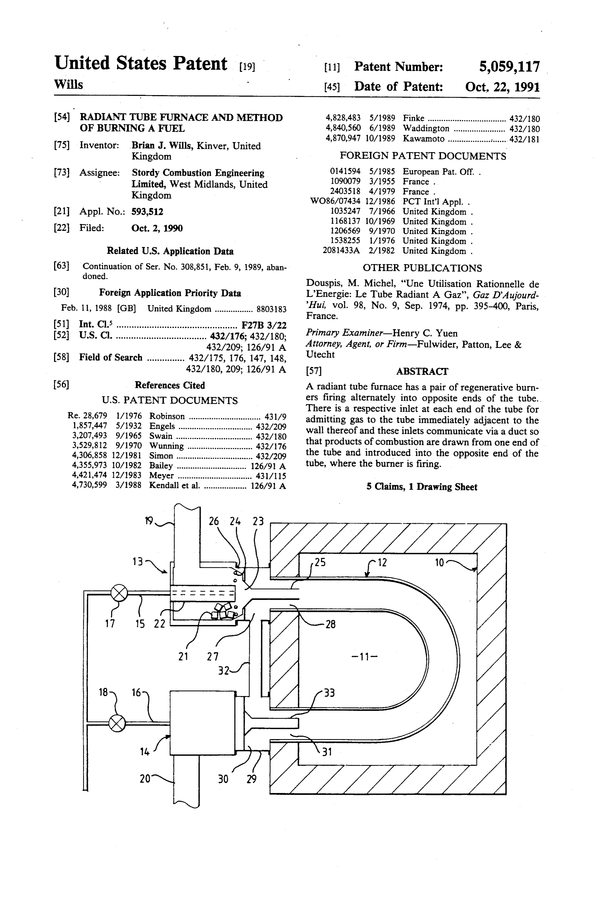
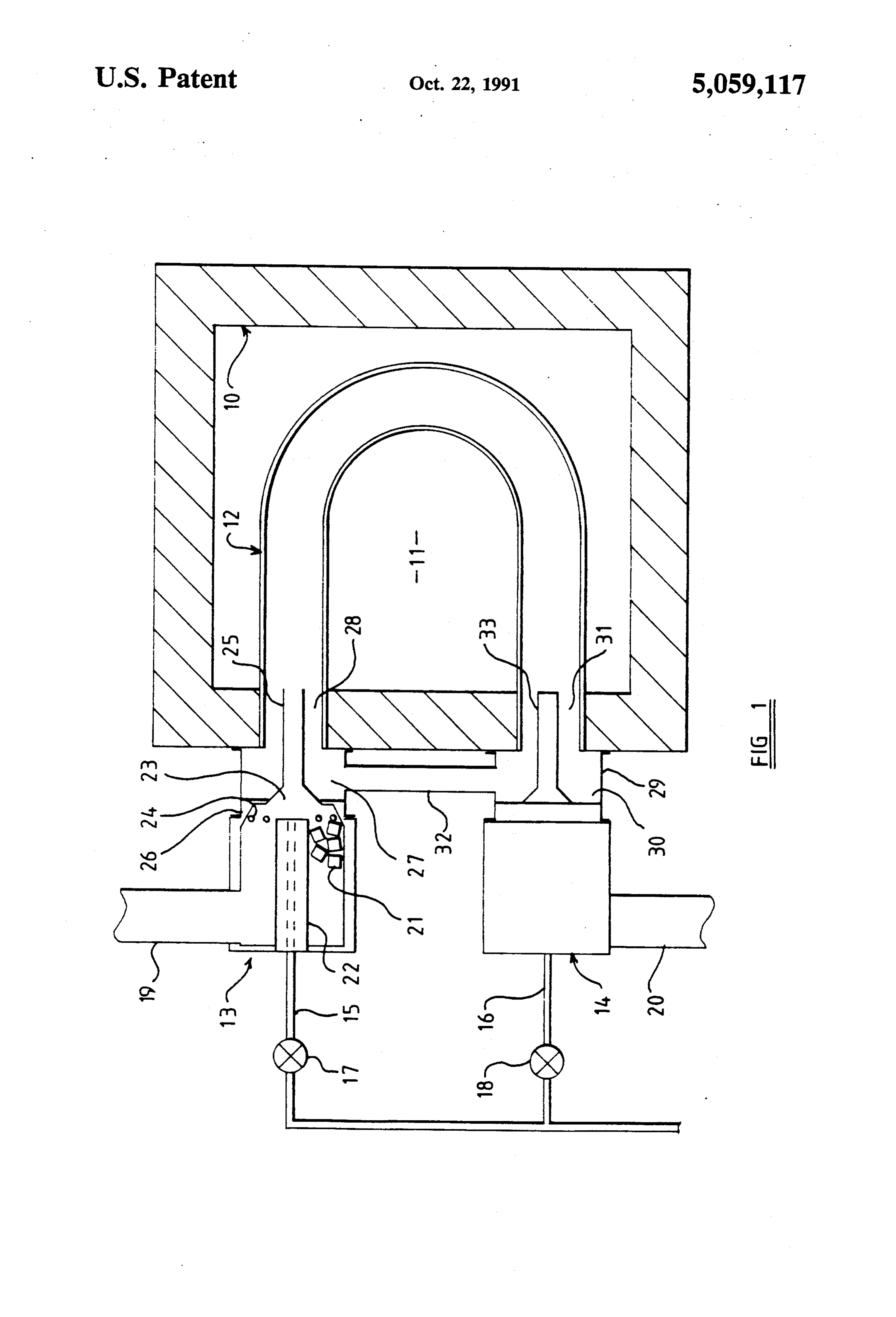
a temperature approximately equal to that of the end portion of the tube. To avoid heating of the end portion BRIEF DESCRIPTION OF THE DRAWING of the tube to a temperature at which deterioration of An example of a furnace embodying the present in the tube is likely to occur, it is desirable to provide a vention and which is used for burning a fuel by a shield of sleeve-like form between the end portion of 40 method in accordance with the invention will now be the tube and the burning mixture inside the tube. This described, with reference to the accompanying draw shield may be formed by the further gas admitted to the ing, which shows diagrammatically a cross-section tube, or may a fixed shield formed of solid material or through a furnace having two regenerative burners, these two forms of shield may be used in combination. internal parts of one only of these burners being shown. The invention is applicable with especial advantage in a 45 case where the burning mixture of fuel and air is di DESCRIPTION OF PREFERRED EMBODIMENT rected into the tube from a regenerative burner, since The furnace illustrated in the drawing has a wall 10 heating of the combustion air in a regenerative burner enclosing a chamber II in which material or workpieces results in a relatively high flame temperature. is or are to be heated. A substantially U-shaped tube The further gas is preferably substantially devoid of 50 extends into the chamber II from the wall at one side of free oxygen and is preferably non-combustible. The the chamber, with end portions of the tube being dis further gas may include products of combustion of the posed in respective openings formed in the wall. The fuel in the tube, these products being circulated through general arrangement and construction of the furnace, the tube. It will be understood that a fraction only of the including the wall 10 and the tube 12, may be those of a products of combustion would be circulated through 55 known furnace and will not be further described. the tube to provide the gaseous shield. A further frac Regenerative burners 13 and 14 are mounted at the tion of the products of combustion may be exhausted outside of the furnace wall 10 in alignment with respec from the tube through heat storage means which ex tive end portions of the tube 12. Fuel lines 15 and 16 are tracts heat from the products of combustion and subse provided for supplying fuel to the burners from a suit quently imparts that heat to combustion air. able source, for example a natural gas main. Control Whilst it would be within the scope of the invention means of the burners includes valves 17 and 18 for con to cool that fraction of the products of combustion trolling the flow of fuel along the fuel lines. The burner which are to be circulated through the tube to provide 13 has an inlet duct 19 along which combustion air can the gaseous shield, it is believed that the temperature of flow to the burner and along which products of com the products of combustion leaving the tube will be 65 bustion can leave the burner and pass to the atmosphere sufficiently low for the products of combustion to pro through a suitable stack. The burner 14 has a corre vide an effective shield, without further cooling of the sponding inlet duct 20 for leading combustion air to the products of combustion prior to admission of those burner 14 and for conveying products of combustion
Page 4
from that burner to the stack. The control means in housings 26 and 29 and the duct 32 may be insulated cludes valves for connecting the inlet ducts 19 and 20 in externally against heat loss.
turn with the stack and with a fan or other means for When the burner 13 is firing, fuel and air are supplied supplying the combustion air. to that burner. The fuel is directed through the mixing The burners 13 and 14 are identical one with the position 23 along the interior of the guide 25. The air other and therefore the arrangement of the burner 13 passes through the bed 21, where it is heated, and then only will be described and is shown in the drawing. The passes through the mixing position 23 and along the burner contains an annular bed 21 of refractory ele interior of the guide. Some degree of mixing of the fuel ments which is in direct communication with the inlet and air occurs at the mixing position so that a flame is duct 19. The inner periphery of the bed is defined by a 10 established inside the guide 25. However, thorough tube 22, along the interior of which the fuel line 15 mixing of the fuel and air is not achieved at the mixing extends to or almost to a mixing position 23 which lies position. Mixing continues as the gases flow along the adjacent to that end of the tube 22 which is nearer to the guide 25 and may continue after the burning mixture has radiant tube 12. The mixing position 23 is separated left the guide 25 and flows along the interior of the from one end of the bed 21 by retaining means 24 for 15 radiant tube 12. Typically, the flame extends at least to preventing the refractory elements falling from the bed the bend in the tube. Products of combustion flow along into the mixing position. The retaining means is of a the tube towards the burner 14. A first portion of the form which provides little obstruction to the flow of air products of combustion flows along the interior of the from the bed to the mixing position and which does not 20 guide 33 associated with the burner 14 and then through promote severe turbulence in air flowing from the bed the bed of refractory elements contained in that burner, to the mixing position. The retaining means may, for so heating the refractory elements, before this portion example, comprise a number of bars which are spaced of the products of combustion is discharged to the at from each other and from the tube 22 by relatively large mosphere. A complementary portion of the products of gaps for the unobstructed flow of air. combustion flows through the annular space 31 into the The burner 13 further comprises a hollow guide 25 25 inlet chamber 30 and from there through the duct 32 to for guiding air from the bed 21 and fuel from the fuel the inlet chamber 27. From this inlet chamber, the prod line 15 into the tube 12. The guide includes a divergent lar ucts of combustion flow into the tube 12 along the annu end portion of conical form which surrounds the mixing bustion space 28. It will be noted that the products of com position 23 and which is held in substantially fluid-tight 30 fined to entering the tube along the space 28 are con relation with an annular body of the burner surrounding cent to the wall of the a region of tube which is immediately adja the tube. The flow of products of the bed 21. An opposite end portion of the guide is of combustion is distributed substantially evenly around cylindrical form, extends into the adjacent end portion the circumference of the tube. of the tube 12 and extends at least along that end portion The products of combustion entering the tube 12 of the tube which is surrounded by the wall 10. The 35 through the annular space guide may protrude somewhat beyond the internal face burning mixture of fuel and28airform and a shield between the the wall of the tube of the wall 10. It will be noted that the guide 25 is ar 12. This shield is maintained downstream ranged as a cantilever and is supported only at its coni 25, although turbulence of the gases withinofthethetube guide
cal end portion. Accordingly, the guide is formed of a will disrupt the gaseous shield so that the shield is not robust material which can withstand particularly high maintained throughout the tube. Typically, the shield temperatures, without deterioration. An example of a will cease to be effective at a position upstream of the suitable material is silicon carbide. bend in the radiant tube.
There is interposed between the burner 13 and the When one half cycle of operation of the burners has furnace wall 10 a housing 26 inside which there is an been completed, the supply of fuel and air to the burner annular inlet chamber 27 surrounding a part of the guide 45 13 is terminated and firing of the burner 14 commences. 25. Typically, the housing has an outwardly projecting This changes the pressure and velocity conditions flange at each of its ends, one of these flanges being within the radiant tube secured by bolts to the wall 10 and the other flange products of combustion is12induced in such a way that flow of in the opposite direc being secured by bolts to a corresponding flange of the tion along the duct 32. Thus, products of combustion burner 13. 50 flow from the tube 12 into the chamber 27 and thence The outside diameter of that part of the guide 25 through the duct to the chamber 30. The products of which lies within the end portion of the tube 12 is con combustion flow from the chamber 30 into the tube 12 siderably less than is the internal diameter of the end to form a gaseous shield in a manner analogous to that portion of the tube. Accordingly, there is an annular hereinbefore described.
space 28 between the guide and the tube. This space 55 Those end portions of the tube 12 which are closely communicates directly with the chamber 27 and so surrounded by the wall 10 are shielded from the burner provides direct communication between the inlet cham flames by the guides 25 and 33 and also by the gaseous ber and the interior of the radiant tube. shields. Further portions of the wall of the tube 12 are A housing 29 corresponding to the housing 26 is shielded from the hotest parts of the flames by the gase interposed between the burner 14 and the furnace wall ous shields. Even though the regenerative burners pro 10. This housing defines an inlet chamber 30 which duce flames having very high temperatures, the wall of communicates with the interior of the radiant tube the tube 12 is not subjected to an excessively high tem through an annular space 31 corresponding to the space perature and the imparting of heat to the tube wall is 28. A duct 32 extends between the housings 26 and 29, distributed more evenly along the tube than would be providing direct communication between the inlet 65 the case in the absence of the gaseous shields. chambers 27 and 30. In the example shown in the draw The shape and size of the duct 32 and of the inlet ing, this duct lies outside the furnace wall 10 but nearer chambers 27 and 30 can be selected to provide for the to the furnace wall than are the burners 13 and 14. The required flow rate of products of combustion through
Page 5
the duct. If required, a valve may be associated with the with air generating products of combustion through a duct, in order that the resistance to flow of gases tube having an interior wall to heat the tube and cause through the duct can be varied. Up to one half of the the tube to radiate heat, for an indefinite number of products of combustion may be circulated. cycles, each cycle having a first part during which the In a first modification of the arrangement illustrated burning mixture of fuel and air enters the tube at a first in the accompanying drawing, the duct 32 is disposed in end thereof, a first portion of said products of combus the furnace wall 10 or in the chamber II and provides tion leave a second end of the tube, cooling said prod direct communication between the annular space 28 and ucts of combustion by heat storage means, a second the annular space 31. In a further modification, a pair of portion of said products of combustion leaving the sec ducts is substituted for the duct 32. One of these ducts 10 ond end of the tube flowing to the first end of the tube connects the inlet duct 19 with the inlet chamber 30 and without passing to the heat storage means, and each the other connects the inlet duct 20 with the inlet cham cycle having a second part during which the burning ber 27. Valves may be provided for opening these ducts mixture of fuel and air enters the tube at the second end alternately so that products of combustion which have thereof, heating the air by the heat storage means, cool been cooled by one of the burners are returned to the 15 ing a first portion of said products of combustion leav radiant tube at the end thereof into which the other ing the tube at the first end thereof by the heat storage burner is firing. means, a second portion of the products of combustion Whilst the invention is conveniently applied to a leaving the tube at the first end thereof flowing to the furnace having a radiant tube which is generally U second end of the tube without passing to the heat stor shaped, it will be understood that the invention may 20 age means, whereby products of combustion are circu also be applied to a furnace having a rectilinear radiant lated through the tube, wherein said second portion is tube. Furthermore, the invention may be applied to a admitted to the interior of the tube adjacent to the wall furnace having a burner at one end only of the tube, thereof and wherein said second portion forms a shield rather than a pair of regenerative burners which fire between the burning mixture and a part of the tube wall. alternately into the same tube. 25 4. A method of burning a fuel to supply heat to con Whilst products of combustion from the radiant tube tents of a chamber, comprising the steps of: constitute a readily available mixture which will not directing a burning mixture of the fuel with air contribute significantly to combustion in the radiant through a tube having an interior wall which ex tube, other sources of gas may be used to provide a tends through the chamber to heat the tube and gaseous shield. Although a shield which will not partici 30 cause the tube to radiate heat to the contents of the pate substantially in combustion occurring within the chamber in an indefinite number of cycles, each radiant tube is preferred, the shield may be formed of or cycle having a first part and a second part, said first include air. The air may be relatively cool air or air part comprising the steps of directing the burning which has received heat derived from products of com mixture of fuel and air into a first end of the tube in bustion leaving the radiant tube. 35 a first direction to generate first products of com If air is introduced so that the shield includes oxygen, bustion within said tube, discharging said first the mixture flowing through the guide 25 may be corre products of combustion from a second end of said spondingly fuel-rich. This promotes a long flame and tube, and storing heat from said first products of lower flame temperature. combustion; said second part comprising the steps We have found that gaseous shields help to avoid of heating air for the burning mixture of fuel and air very high flame temperatures and therefore contribute with heat stored from said first part, directing the to low concentrations of oxides of nitrogen in the gases burning mixture of fuel and heated air into the discharged. second end of the tube in a second direction to What we claim is: generate further products of combustion within 1. A method of burning a fuel to supply heat compris 45 said tube, discharging said further products of com ing the steps of: directing a burning mixture of the fuel bustion from said first end of the tube, and storing with air through a tube to heat the tube and cause the heat from said further products of combustion; and tube to radiate heat for an indefinite number of cycles, admitting a further gas to the tube adjacent to the directing the burning mixture of fuel and air into the interior wall thereof to flow along the tube in said tube at a first end thereof generating products of com 50 first direction to form a shield between the burning bustion, discharging said products of combustion from a mixture and a part of the tube wall adjacent to the second end of the tube and storing heat from said prod first end of the tube in said first part of each cycle, ucts of combustion during a first part of each cycle; and to form a shield between the burning mixture directing a burning mixture of fuel and air into the tube and a part of the tube wall adjacent to the second at the second end thereof generating further products of 55 end of the tube during said second part of each combustion, heating the air with heat stored from said cycle.
first part of each cycle, discharging said further prod 5. A radiant tube furnace for burning a fuel to supply ucts of combustion from the tube at the first end thereof, heat, said furnace comprising: a radiant tube with an and storing heat from said further products of combus interior wall and first and second ends; means for direct tion during a second part of each cycle; and admitting a ing a burning mixture of the fuel and air into the first further gas to the interior of the tube adjacent to the end of the tube to generate first products of combustion wall thereof to form a shield between the burning mix within the tube; means for discharging said first prod ture and a part of the tube wall. ucts of combustion from the second end of the tube 2. A method according to claim 1 wherein substan including means for storing heat from said first products tially all products of combustion are discharged 65 of combustion; means for heating air for the burning through a heat storage means. mixture of fuel and air with heat from said means for 3. A method of burning a fuel to supply heat compris storing heat; means for directing the burning mixture of ing the steps of directing a burning mixture of the fuel fuel and heated air into the second end of the tube to
Page 6
generate further combustion products within said tube; between the burning mixture and a part of the tube wall means for discharging said further products of combus- adjacent to the first end of the tube and to form a shield tion from said first end of the tube, including means for between the burning mixture and a part of the tube wall storing heat from said further products of combustion; adjacent to the second end of the tube. and means for admitting a further gas to form a shield 5 it sk i k it
Provenance
- Collection
- Patents citing this work
- Original assignee
- Fives North America Combustion UK Ltd
- Pages
- 6
- Method
- pdftotext (the PDF's own text layer) + pdftoppm 300dpi page scans
- Patent office record
- patents.google.com →
- Source
- Google Patents citing-documents table
- Inventors
- Brian J. Wills; Fives North America Combustion UK Ltd
- Published
- 1991-10-22
- Transcribed from
- patentimages.storage.googleapis.com →