patent · US3529812
Burner with air-preheated recovery
22 September 1970
Page 1
Drawing sheet — no readable text.
Page 2
Drawing sheet — no readable text.
Page 3
United States Patent Office 3,529,812 Patented Sept. 22, 1970
able flame formation develops in the burner. Moreover,
BURNER WITH AR-PREHEATED RECOVERY the heat exchange canals are relatively small so that a good Joachim Wunning, Warmbronn, Germany, assignor to heat exchange is ensured while still providing a relatively Firma J. Aichelin, Korntal, Germany, a firm of Ger large free space within the air duct cylinder which can many 5 be used for ignition devices, air cooling ducts with oil Filed Aug. 15, 1968, Ser. No. 784,963 nozzles, or the like.
Claims priority, application Germany, Aug. 17, 1967, The invention will be more fully understood from the
following detailed description taken in conjunction with
the accompanying drawings, wherein:
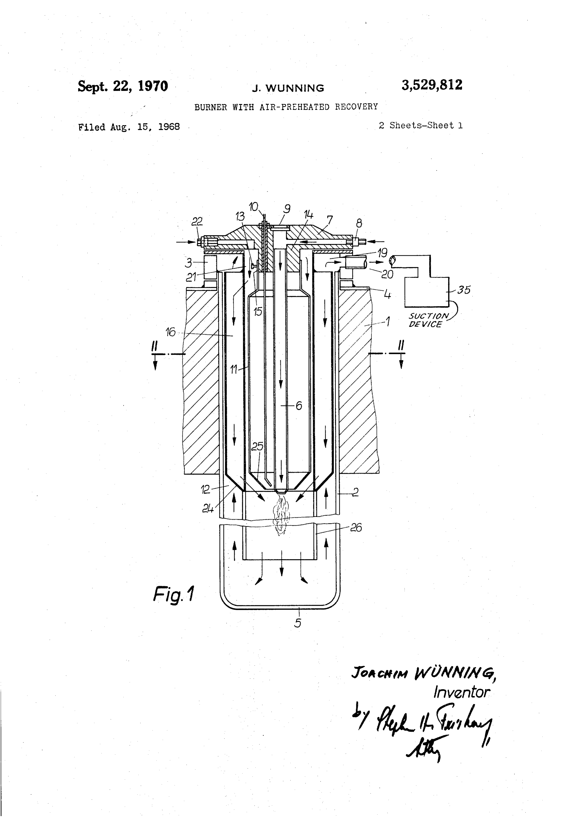
O FIG. 1 is a sectional view of a jacket jet heating tube having a burner according to the invention;
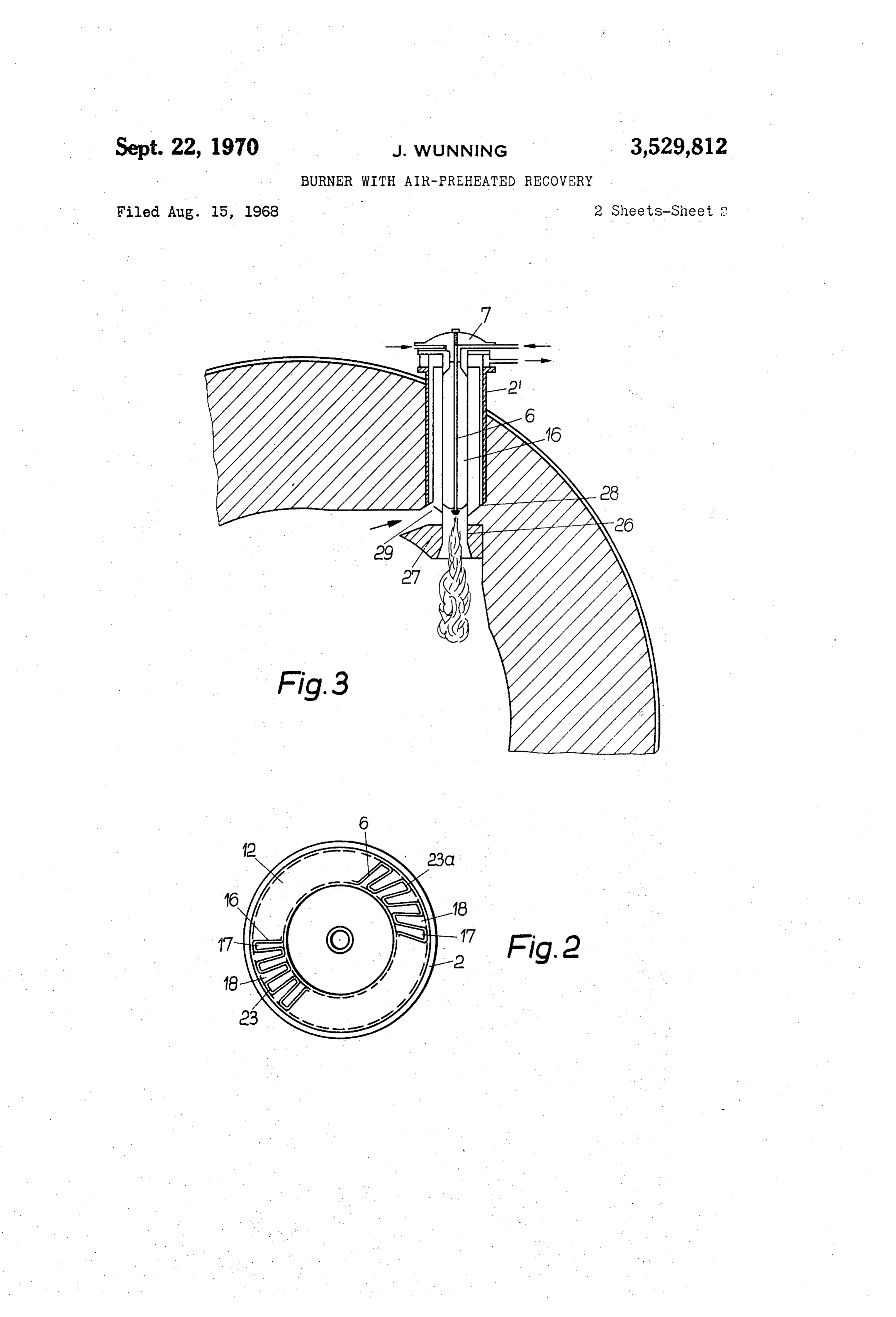
ABSTRACT OF THE DISCLOSURE FIG. 2 is a sectional view of the jet heating tube of FIG. 1 taken along line II-II; and
An industrial burner having a recuperative air pre FIG. 3 is a sectional view of another industrial burner heating device including an air duct cylinder mounted according to the invention.
around the burner and forming an annular gap between Referring now to FIGS. 1 and 2, a jacket jet heating the air duct cylinder and a jacket tube. Means, such as an tube is mounted into a furnace wall 1. The heating tube accordion-type folded body, is mounted in the annular comprises a jacket tube 2 of heat resistant material which gap to provide a plurality of radially extending partitions is fastened on one end to furnace sheet 4 via members 3. which form a plurality of axial canals in said annular Tube 2 is terminated at its other end by an end portion 5 gap. Air flowing in alternate canals is preheated by heat made of the same material as 2. Within jacket tube 2 is transferred thereto from the hot flue gases flowing in a centrally arranged tubular-shaped fuel nozzle 6. Nozzle the remaining alternate canals. 6 is mounted in a lid 7 and fuel, such as oil or gas for example, is fed thereto via duct 8. An inspection hole 9 25 is provided and an ignition electrode 10 is mounted to
The invention relates to industrial-type burners, prefer 1id 7.
ably for gaseous fuels, and more particularly to burners Fuel nozzle 6 is surrounded by a concentric air duct having heat exchange surfaces for preheating of air. cylinder 11 which cooperates with jacket tube 2 to form In prior art industrial burners using jet heating tubes an annular gap 12 therebetween. Cylinder 11 is necked and more particularly burners having jacket jet heating 30 down at its upper end and is fastened to a cylindrical mem tubes, incoming air flowing in a direction opposite to the ber 14 of lid 7 by means of screw 15. This mounting ar rangement allows adjustment of the position of cylinder waste gases, is preheated on its way to the mouth of the burner nozzle. For this purpose a rib recuperator is gen and 11. In the annular gap 12 between air duct cylinder 11 erally provided which consists mainly of radially posi formed jacket tube 2, axially extending canals 17 and 18 are tioned heat exchange sheets which extend in an axial di by means of axially extending partition walls 16. rection in the air supply canal over which flows the air Alternate canals 17 and 18 are designated as air canals to be heated. These sheets have additional portions which 17 and as flue gas canals 18. Flue gas canals 18 are con nected to a waste gas collecting duct 19 which ends in project into a waste gas discharge canal in which the hot waste gases flowing over the additional portions of the 40 a waste gas discharge connection 20 connected to a suc sheets transfer heat to said sheets. A heat transfer ef tion draft device 35. The air supply canals 17 are con ficiency rate of about 70% can be achieved with such nected with an annular space 21 through which air enters known rib recuperators at furnace temperature of around from an air supply duct 22.
900 C. While this efficiency is acceptable in many in The subdivision of the annular gap 12 into axial canals 17, 18 (that is, the formation of partition walls 16) is dustrial furnaces, there was a need for further improve accomplished ment of the degree of efficiency of the burners. There was by inserting a molded sheet body 23 into also a need for such a more efficient burner which also the annular gap 12. The molded body 23, as can be seen reduces the temperature of the waste gases. from FIG. 2 (left side), is folded in accordion like man Therefore, the main object of this invention is to pro jacketner. The folds on one side of body 23 cooperate with vide a burner which is more efficient than the above tube 2 to define the axial flue gas canals 18, and the described known burners, which does not require in folds on the other side of body 23 cooperate with creased space, which is economical to manufacture and cylinder 11 to define the air supply canals 17. The molded operate, and which emits exhaust gases having reduced sheet body 23 consists of a heat resistant material. The temperatures. molded sheet body 23 can also be formed from a number of sheet strips of different materials, because a higher
SUMMARY OF THE INVENTION 5 55 temperature is present substantially in the area of the mouth of burner nozzle 6.
According to this invention, a burner comprises a cen Air supply duct canals 17 are terminated at their lower tral fuel nozzle and an air duct cylinder surrounding the nozzle. A jacket tube surrounds and is spaced from the ends by walls 24 at the front side facing the mouth of air duct cylinder to form an annular gap therebetween. 60 burner nozzle 6. The walls 24 are arranged in an oblique manner inclined toward the axis of the burner tube 6
Also provided is an air inlet and a flue gas outlet. Fur ther provided is means forming a plurality of axial canals to permit all air in canals 17 to escape towards the burner. In the lower portions thereof, the partition walls 16, as within the annular gap, alternate ones of the axial canals can be seen from FIG. 1, can also be cut in a correspond being connected as air supply canals for the fuel nozzle ing oblique manner. Air duct cylinder 11, in the area of and the remaining alternate canals being connected as the burner nozzle mouth, has a conical ring-shaped front flue gas canals for conducting flue gas from the nozzle. wall 25, which, as indicated by air flow arrows in FIG. 1, Heat contained in the flue gases is conducted to the supply conducts the air escaping from air canals 17 substantially air through the walls of the radially extending canals.
The above described type of burner according to this laterally into the flame of burner 6. invention provides relatively large heat exchange surfaces 70 Further provided is an interior tube 26 which is secured between the gas discharge and air supply canals. Also, due to the molded sheet body 23 in the vicinity of the extended to the multiple subdivision of the air canals, a very favor lower part of air duct cylinder 11. Interior tube 26, which
Page 4
surrounds the flame and is normally provided in well nular gap 12 is small enough so that there is sufficient known jacket jet heating tubes, conducts the flue gases space for the accommodation of auxiliary devices, such developed during the combustion, in the direction indi as ignition devices and the like, while using a burner cated by arrows in FIG. 1, into the annular gap 12. The having the same length and the same outer diameter flue gases then enter flue gas canals 18 and are prevented as the known prior art burners. The improved burner from entering the air supply canals 17 by front walls 24 according to this invention provides a kF value (k=heat which close of canals 17. transfer number, F=heat exchange surface) several times The molded sheet body 23 shown in FIG. 2 on the left higher than comparable conventional designs. The kF side, has partition walls 16 which are substantially radial, value is a well known characteristic which is used for ex the edges of the folds of sheet 23 extending parallel to O pressing the efficiency of such a recuperator. The actual the burner axis. In a variation of the invention, a molded burner which was built featured a jacket tube 2 having sheet body 23a (indicated on the right side in FIG. 2) an outer diameter of 150 mm. The length of the recuper is shaped in such a manner that the folds thereof run. ator, that is of the folded molded-sheet part 23 was about tangentially with respect to the burner axis so that the 400 mm., which corresponds to a normal industrial fur escaping air, at the mouth of the burner nozzle 6 is nace so that the recupreator does not project to the provided with a twist. This results in a twist flame being outside.
produced. The folds of sheet 23a can run in spiral-like At a furnace temperature of 950° C. and a jet tube manner; the characteristics of the twist can be adjusted to load of 15,000 kcal./hr., a flue gas temperature of 350° C. the specific requirements to provide the desired air flow. was obtained at the burner outlet. This corresponds to Referring to FIG. 3, a burner similar to that of FIGS. a furnace efficiency rate of more than 85%. A very favor 1 and 2 is shown wherein the same elements are given able flame formation was achieved, which is due, at least the same reference numerals. In this embodiment, how in part, to the multiple subdivision of the current of Supply ever, interior tube 26 is inserted into a perforated burner air. The supply air was preheated to about 750° C. at the stone 27 and jacket tube 2 is open at its lower end 28 mouth of the burner nozzle 6-up to a point above the which is located toward the interior space of the furnace. 2 5 ignition temperature of the fuel. This further enhanced Thus the flue gases coming from burner stone 27 enter the performance of the burner under test. the interior furnace space. From there they can enter Due to the high degree of efficiency, a gas-air mix through an annular space 29, located between burner ture control is not necessary with the new burner ac stone 27 and the front wall of jacket tube 2 (at 28) into cording to this invention since even at 100% air excess, flue gas canals 18, which canals are not shown in detail 30 the degree of efficiency was still found to be above 70%. since the arrangement of FIG. 3 is the same as the ar In addition, due to the low flue gas temperature at the rangement of FIGS. 1 and 2. burner outlet, the attending personnel is much less in The molded body 23 of FIGS. 1 and 2 may be made by convenienced by the effect of the heat in the vicinity of means of any well known method. One such method con the furnace. This is of importance in view of present sists of shaping a sheet metal strip of suitable heat resist 35 requirements with regard to industrial hygiene. ant material between two rollers into a corrugated sheet Another advantage of the low flue gas temperature at type form. The corrugated metal strip is then gathered the burner outlet is that it is now possible to connect together to form the accordionlike folds shown in FIG. 2. the flue gas canals on one side to a suction draft device. The corrugated strip is then provided with front walls 24 With flue gas temperatures below 400° C., no important on alternate channels thereof which are welded on and 40 design problems are present with regard to suction draft directed such that the supply air is blown into the flame blowers and throttle valves. Also, air quantity controls, of the burner 6 in substantially a lateral direction. The such as nozzles, may be provided in the area of the air sheet-molded body 23 is then bent around and inserted entry into the air supply canals. In this case the air dis into the annular gap 12, as shown in FIGS. 1 and 2. tribution duct required in pressure operation and the mix It should be clear that the accordionlike sheet-molded ture control are not necessary. Fuel is then brought to the body 23 can be replaced by a plurality of individual par various jet tubes of the furnace at substantially Zero pres tition walls which are placed within the annular region sure. The actual quantity control of fuel can be effected 12. Suitable means will then be provided for securing with a throttle unit in the flue gas duct by a burner or the partition walls in place. In order to produce a twist a group of burners. Also, the use of suction with jet tubes flame with this type of construction, the longitudinal equipped with the above-described burners is desirable edges of the individual partition walls must be directed for the reason that when the steel tubes are slightly per in a tangential manner or in a spiral-like manner with meable no flue gas can penetrate into the furnace and respect to the axis of the burner 6. The particular design impair any protective gas atmosphere possibly present of such a configuration should be clear to those ordinarily there.
skilled in the art within the spirit of this invention. 55 It should be clear that this invention is not confined to In order to vary the exit speed of the supply air from application in only burners having jacket jet heating the individual air supply canals in the area of the mouth tubes. All furnaces which remain closed during operation of the burner nozzle 6, the air duct cylinder is arranged or must be opened only temporarily, can be equipped in such a manner that it can be axially shifted. This is with burners according to this invention to provide im accomplished by means of loosening the set screw 13 and axially adjusting the position of cylinder 11. The set 60 proved performance.
What is claimed is:
screw 13 is re-tightened when the desired position is 1. A burner comprising:
reached. This effectively varies the dimensions of the a central fuel nozzle (6);
opening between slanted walls 24 and 25, which in turn a jacket tube (2) surrounding and spaced from said varies the exit speed of the supply air. nozzle (6);
In order to improve the heat transfer from the gas in an air inlet (22);
the flue gas canals to the air in the air supply canals, a flue gas outlet (20); and bodies which increase the turbulence of the air or fue recuperative air preheating means including: gas flowing in the canals may be provided. For example, an air duct cylinder (11) mounted within the space wire nets or screens may be provided in the canals. w between said nozzle (6) and said jacket tube (2); A burner was built according to the invention and was an annular gap (12) being formed between said cylin examined and tested in detail to confirm the above der (11) and said jacket tube (2); mentioned clear advantages over conventional types of and means (23) forming a plurality of axially ex burners. The “fold recuperator” which, according to the tending canals (17, 18) within said annular gap invention, is accommodated in the relatively small an 5 (S2) comprising a plurality of axially directed pars
Page 5
tition walls extending transverse to the axis of the of the folds of said molded sheet (23a) run tangen cylinder, alternate ones of said canals (17) being tially in a spiral-type manner with respect to the axis of coupling to said air inlet to supply air to said nozzle said burner.
(6), the remaining alternate axial canals (18) being 9. A burner according to claim 1, wherein said air duct coupled to said flue gas outlet (20) for conducting 5 cylinder (11) includes means (13) for enabling the posi flue gases from said nozzle (6), heat from said flue tion of Said air duct cylinder (11) to be shifted in an axial gases being transferred to said supply air via Said direction.
canal forming means. 10. A burner according to claim 3, wherein said 2. A burner according to claim 1, wherein said par molded sheet body (23) is formed from a plurality of tition walls (16) extend substantially radially within said O sheet strips of different materials. annular gap (12). 11. A burner according to claim 1, wherein said flue 3. A burner according to claim 1, wherein said parti gas canals (18) are connected to a suction draft device tion walls are formed by a corrugated folded molded on one side.
sheet (23), the folds on one side thereof cooperating 12. A burner according to claim 5, wherein said par with said jacket tube (2) to define exhaust gas canals 15 tition walls (16) and the folds of the molded sheet part (18) and the folds on the other side thereof cooperating (23) respectively, are chamfered at the ends thereof with said cylinder (11) to define air supply canals (17). which face the mouth of said fuel nozzle (6). 4. A burner according to claim 1, further comprising 13. A burner according to claim 1, further compris means (24) for terminating said air supply canals (17) ing:
on the front sides thereof which face the mouth of said 20 a burner stone (27) having an opening therein; and fuel nozzle (6). an interior tube (26) extending from the lower por 5. A burner according to claim 4, wherein said termi tion of said air duct cylinder (11), said interior tube nating means (24) includes front walls (24) positioned (26) projecting into said opening in said burner such that all of said walls (24) form a conical segment, stone (27), thereby defining a ring area (29) with said walls being inclined toward the center axis of the said jacket tube through which the flue gas enters burner. into said flue gas canals (18). 6. A burner according to claim 5, wherein said air duct cylinder (11) is terminated in a conical ring-disk type References Cited front wall (25) in the area of the mouth of said fuel nozzle (6), such that air leaving said air supply canals 30 UNITED STATES PATENTS (17) is conducted into the flame of said burner along 2,202,498 5/1940 Leaf ------------ 263-20 XR said conical wall (25). 2,985,438 5/1961 Prowler ------------- 263-19 7. A burner according to claim 1, wherein the lon gitudinal edges of said partition walls (16) run tangen JOHN T. CAMBY, Primary Examiner tially in a spiral-type manner with respect to the axis of U.S. Cl. X.R. said burner (6).
8. A burner according to claim 3, wherein the axis 126-110; 263-20
Provenance
- Collection
- Cited prior art
- Original PDF
- patentimages.storage.googleapis.com →
- Filed
- 1968-08-15
- Pages
- 5
- Method
- pdftotext (the PDF's own text layer) + pdftoppm 300dpi page scans
- Source
- Google Patents bibliographic record
- Granted
- 1970-09-22
- Inventors
- Joachim Wunning; Firma J Aichelin
- Transcribed from
- patentimages.storage.googleapis.com →