patent · US4828483
Method and apparatus for suppressing NOx formation in regenerative burners
9 May 1989
Page 1 — bibliographic record
United States Patent (19) (1) Patent Number: 4,828,483 Finke (45) Date of Patent: May 9, 1989 54) METHOD AND APPARATUS FOR 4,740,154 4/1988 Cantoni............................. 431/11 X
SUPPRESSING NOXFORMATION IN
REGENERATIVE BURNERS Primary Examiner-Randall L. Green
Attorney, Agent, or Firm-Webb, Burden, Ziesenheim & (75) Inventor: Harry P. Finke, Pittsburgh, Pa. Webb 73 Assignee: Bloom Engineering Company, Inc., 57 ABSTRACT Pittsburgh, Pa.
A method and apparatus for repressing NOx formation 21) Appl. No.: 198,739 in twinned regenerative burner pairs includes inducing 22) Filed: May 25, 1988 a stream of hot flue gas, preferably containing enriched products of combustion, from the main hot flue gas 51 Int. Cl'....................... F23D 11/44; F27D 17/00 exhaust stream and vitiating the preheated combustion (52) U.S. C. ...................................... 431/11; 431/181; air with the hot flue gas in the firing burner. An inter 431/215; 432/28; 432/180 connecting duct communicating with the twinned 58 Field of Search ..................... 431/11, 5, 207, 328, burner pair includes a coaxial gas nozzle for injecting a 431/181,215; 165/4; 432/28, 181, 182, 180 high kinetic energy gas stream into the exhausting hot (56) References Cited flue gas to induce a portion of the hot flue gas into the
firing burner for vitiation purposes.
3,994,665 11/1976 Young............................... 431/11 X 4,522,588 6/1985 Todd et al. ..................... 432/219 X 19 Claims, 3 Drawing Sheets
Page 2
Drawing sheet — no readable text.
Page 3
Drawing sheet — no readable text.
Page 4
Drawing sheet — no readable text.
Page 5
METHOD AND APPARATUS FOR SUPPRESSING SUMMARY OF THE INVENTION NOXFORMATION IN REGENERATIVE Briefly stated, the present invention comprises a BURNERS paired heat regenerative burner system suitable for di rect firing into a furnace or for use on an enclosed radi
BACKGROUND OF THE INVENTION ant tube burner assembly. The burner pair includes two The invention relates to generally regenerative type identical right and left burner units which individually burners for heating a furnace, and more particularly to and alternately operate in a heating (firing) or exhaust regenerative burners with minimized NOx formation in O /heat reclaiming mode. For ease of description herein the ultimate combustion effluents. This invention is the right hand burner will be assumed to be in the firing related to co-pending application Ser. No. 168,892 enti mode and the left hand burner in the regenerative mode. tled "Low NOx Regenerative Burner' filed Mar. 16, Each of the burners have chambers which are con 1988, the contents of which are incorporated by refer nected at a respective combustion end to a spaced pair ence herein. 15 of first ducts which communicate with the interior of Regenerative-type burners for furnaces are well the furnace or to the tube of a U-shaped radiant tube known in the art in varied forms and designs, but they burner and alternately act to emit hot combustion gases share the common feature whereby heat storage units into the furnace or to exhaust hot flue gases from the are provided to withdraw and store heat from hot com furnace.media bed
Each of the burners have a heat regenerator associated therewith which are respectively bustion effluents known as flue gas, with subsequent 20 connected to a combustion air inlet duct/flue gas outlet transfer of the heat to preheat incoming combustion air. duct.
The earliest regenerative-type furnaces were symmetri A vitiation duct interconnects the two burners on cal arrangements having both burner(s) and heat stor the furnace side of the regenerative media beds and age units (often solid structural arrays of "checker 25 eachcommunicates with the interior chamber portion of chamber' bricks) in place on each of two sides of the chambers burner. A nozzle is positioned at each of the burner furnace. Firing of such a regenerative furnace began stream to alternately inject a high velocity gas with the burner(s) on one side, with concomitant stor into the interconnecting duct. The high velocity age of the heat present in the combustion effluents by stream entrains a portion of the flue gas containing hot the heat storage units on the second side. After optimal products of combustion ("POC') exiting the furnace at heating of the heat storage units, or the "checker cham 30 the left bank burner and causes the entrained hot flue. gas to vitiate the preheated combustion air in the right ber,” the air flow in the furnace was reversed to draw hand burner chamber. The balance of the hot flue gases combustion air in through the checker chamber, thus preheating the combustion air. Ducts in the checker pass through the left bank regenerative media bed to chamber thus alternately conveyed combustion prod 35 transfer its heat thereto for later transfer to a reverse ucts and combustion air, and the burners functioned in flowing stream of combustion air (when the left bank is alternately as burners and as flues. the firing mode). A fuel nozzle or other injector Modern regenerative systems do not involve com means introduces a fuel stream to the mixture of hot plete symmetrical furnaces but instead include special at the right bankflue
POC containing gas and preheated combustion air burner chamber whereby suppressed ized regenerative burners employed, typically, in pairs. or reduced NOx formation in the burner flame is ob Each of the paired regenerative burners is equipped tained. The regenerator sizing is significantly reduced with heat storage units, ordinarily in the form of com while cycle efficiency is also increased due to the fact pact regenerative beds, through which combustion air that the preheat combustion air is vitiated with a hot passes en route to the burner. Because the burners are POC containing flue gas at very high temperatures, for employed in pairs, one burner is fired at a time while the example, between about 1800 to 2000 F. The lowered
other functions as a flue and heat storage bed. Then oxygen content of the vitiated combustion air lowers every 20-120 seconds or so, flow in the furnace is re versed and the burners "exchange' functions, that is, flame the temperatures and minimizes NOx formation while high BTU content of the hot vitiating POC contain the first-fired burner becomes the flue gas exhaust/heat storage bed as the second burner fires. A system exem 50 ingInflue gas contributes to higher furnace efficiencies. plary of one paired burner arrangement is found in U.S. streamoneofpreferred form of the invention, the injected gas is injected tangentially relative to the
A persistent problem with regenerative systems in stream swirling of hot flue gas exiting the furnace to impart a motion to the flue gas to create an enriched volves the extremely high NOx concentrations inevita 55 layer of POC which is then entrained in the vitiating bly present in the combustion effluents, produced as a Stream.
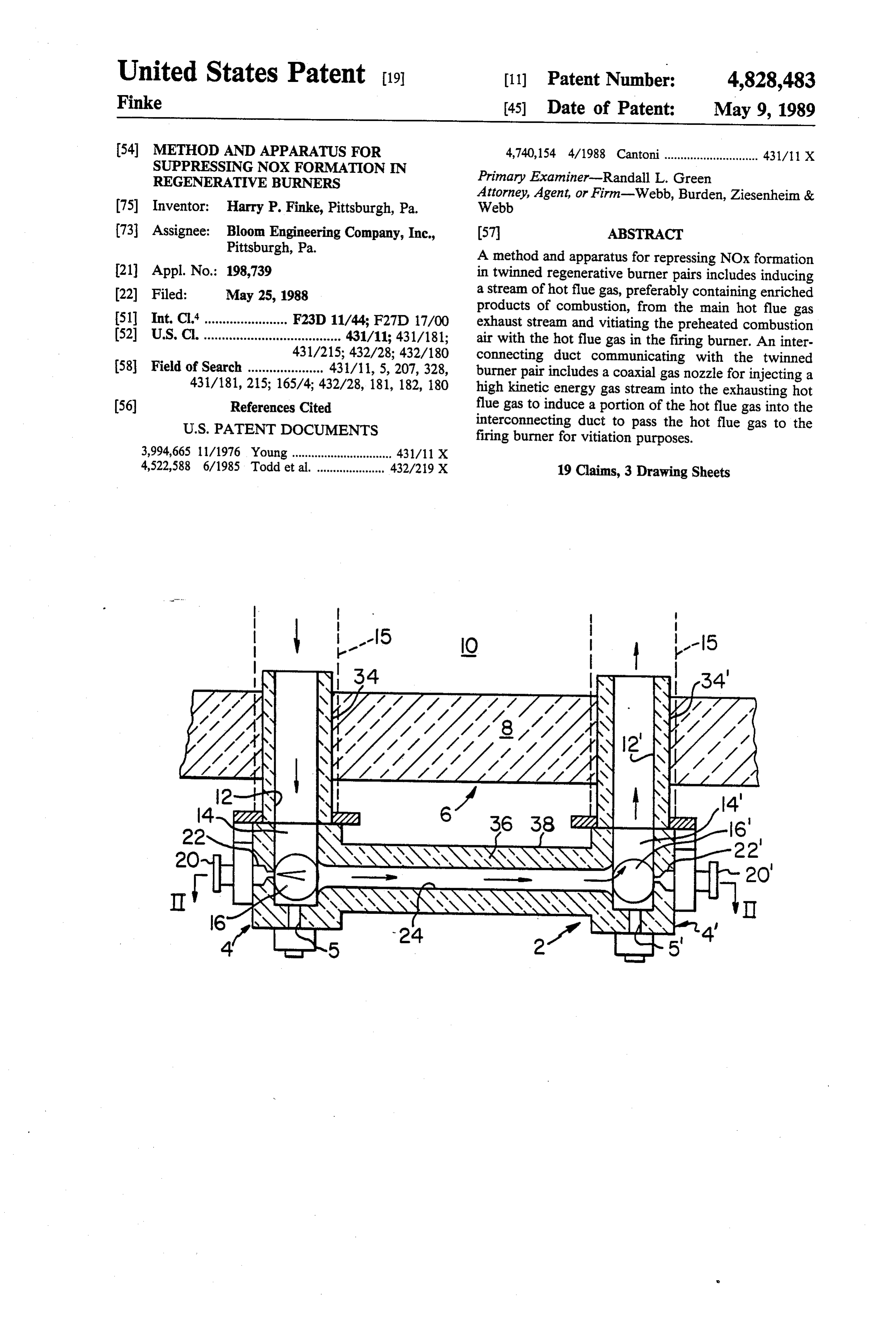
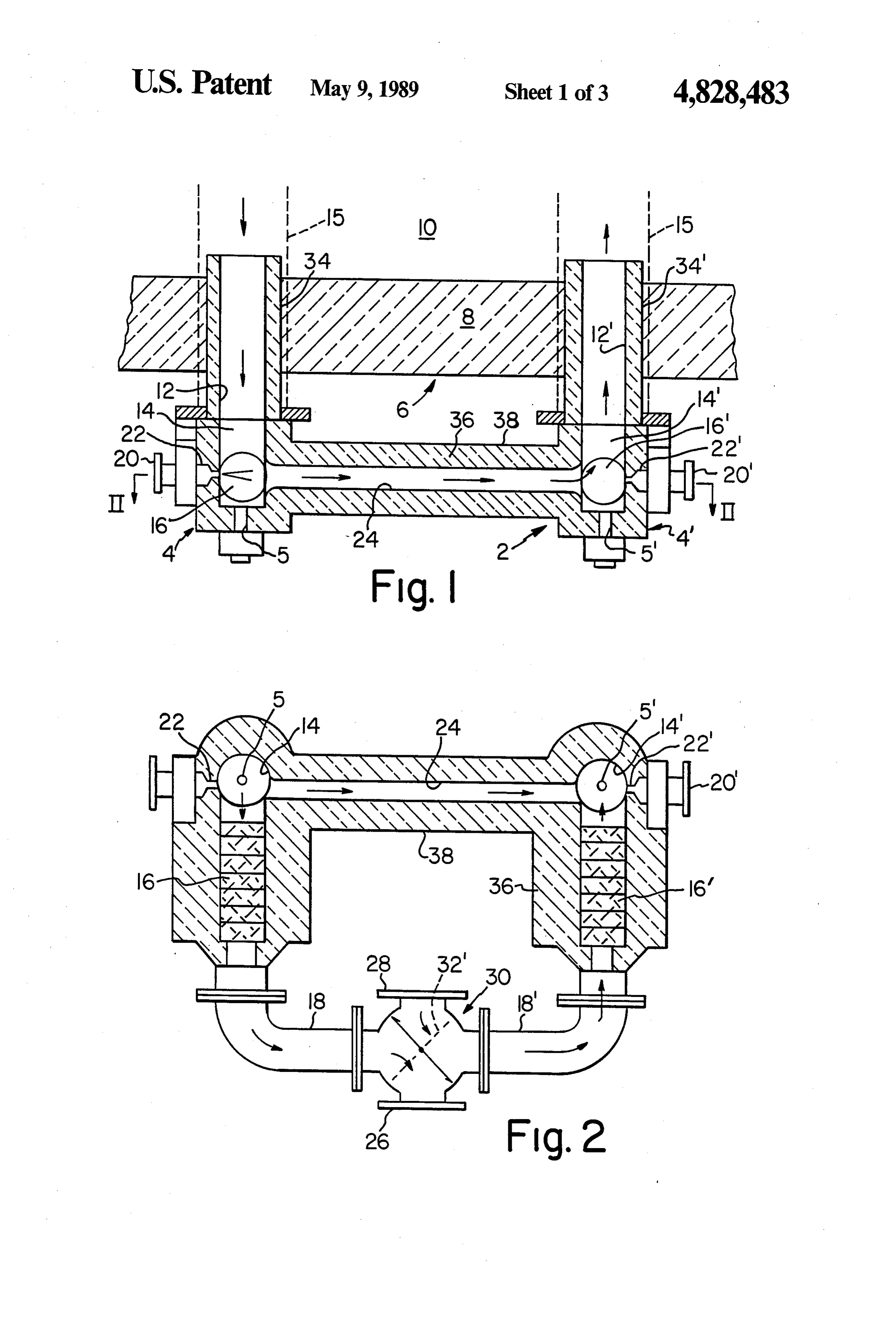
result of the extremely high air preheats and flame tem peratures, as well as through fuel bound nitrogen. As a BRIEF DESCRIPTION OF THE DRAWINGS result, regenerative systems which historically enjoyed FIG. 1 is a schematic plan view of a twinned heat industry-wide acceptance now cannot meet the emis regenerative burner system according to the present sions standards in an ever-increasing number of locali invention;
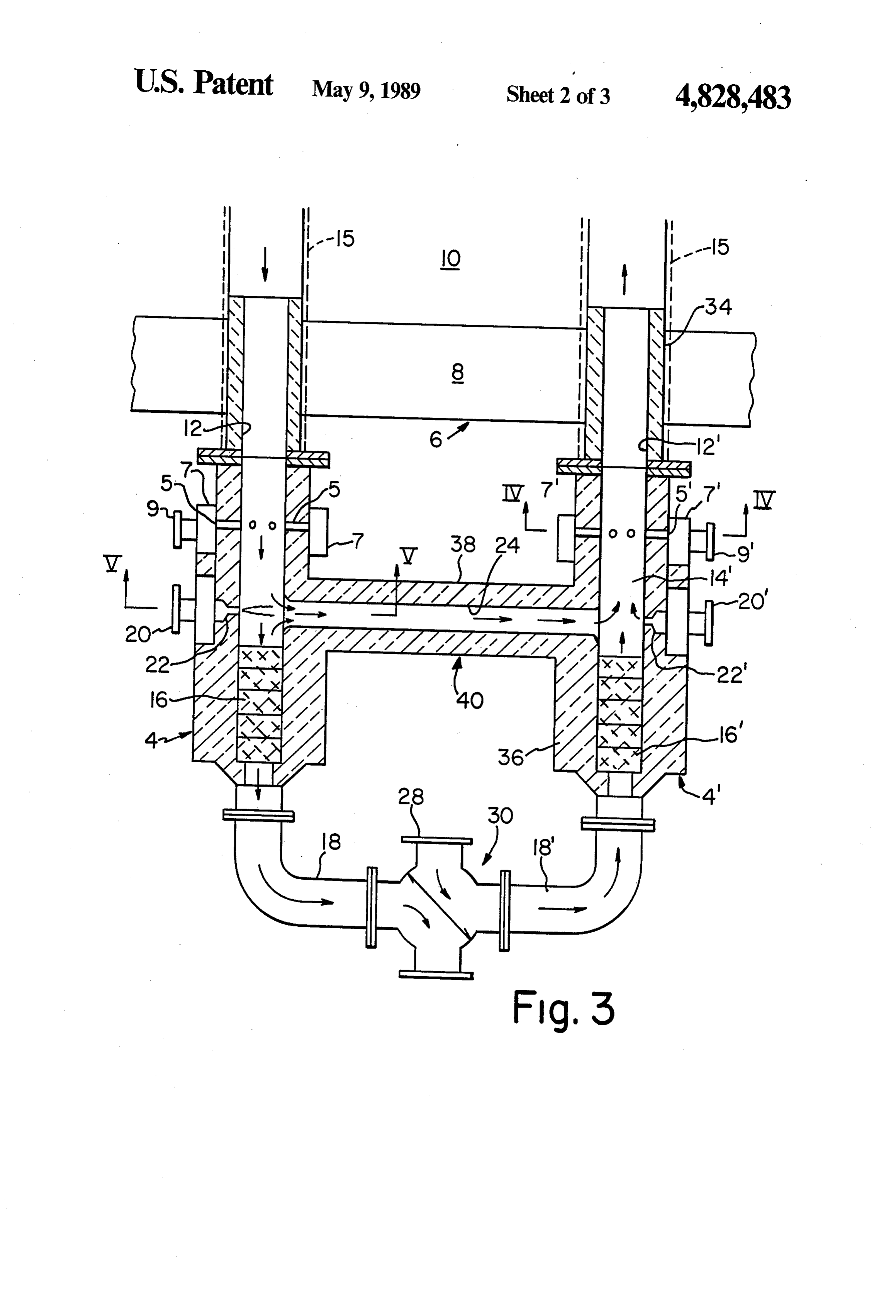
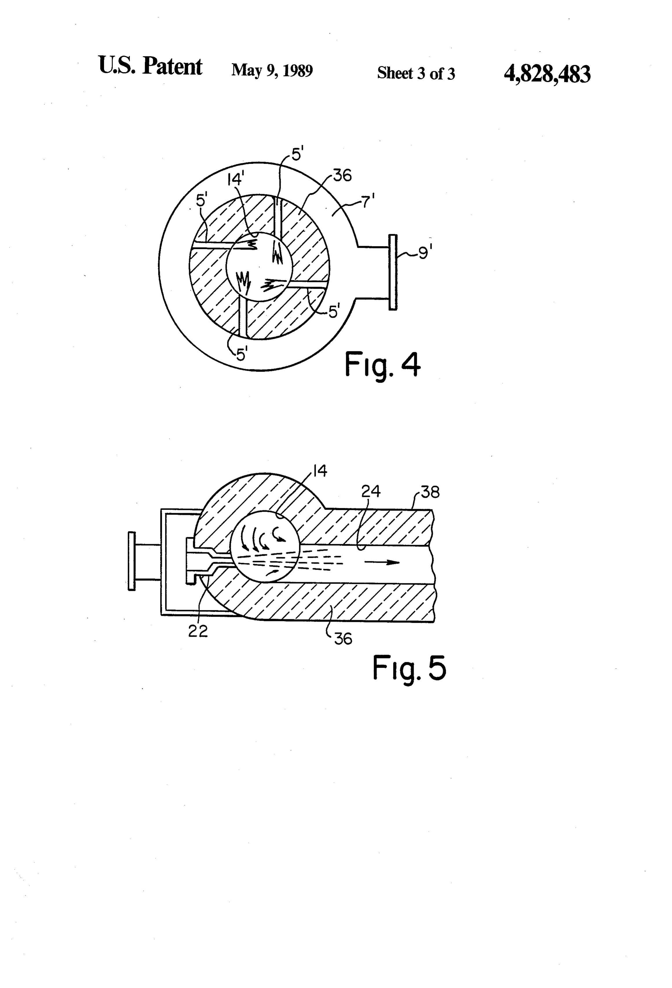
ties and/or process conditions. There is a need for low FIG. 2 is a schematic view in front elevation of the NOx burner concepts which can be broadly adapted to embodiment of the invention depicted in FIG. 1; the specific applications by altering the flame tempera FIG. 3 is a schematic plan view a further embodiment ture to meet NOx emission requirements. A need there 65 of the present invention in the form of twined burners fore persists for regenerative burner systems which having a modified form of fuel delivery; provide the heat-regenerative function of prior art sys FIG. 4 is a cross-sectional view of the fuel injector tems yet provide for significant NOx reduction. manifold taken along lines IV-IV of FIG. 3; and
Page 6
FIG. 5 is a partial cross-sectional view of the gas flue gas leaves the regenerator bed 16 by way of a duct injector left bank burner chamber and interconnecting 18, and is exhausted through a port 26 of a valve assem duct taken along line V-V of FIG. 3. bly 30. A rotatable valve plate 32 directs the cooled flue
DETAILED DESCRIPTION OF THE
gas to the exhaust port 26 of valve 30 and simulta
INVENTION
neously introduces cool combustion air therein by way of a port 28. The combustion airport 28 may be opened
Reference is now made to the drawings in which directly to the atmosphere, in a negative draft mode, or identical elements are designated by identical reference it may be connected to a positive pressure, fan driven numerals throughout the various figures and mirror system, all in a known manner. The cool combustion air images of the same elements are designated by primed 10 passes through the valve 30 and enters a duct 18' where numerals. In FIGS. 1-2, a left bank of a regenerative upon it is passed upwardly through a previously heated burner 4 is shown, with an identical right bank mirror regenerator bed 16. Stored heat in the regenerator bed image, identified in primed numbers. The right bank 16' is given up to preheat the incoming combustion air burner system is generally designated by reference nu which then enters the right hand burner bank 4' at meral 4'. The left and right regenerative burner pair 4 15 chamber 14'. The high velocity gas stream from nozzle and 4 is mounted within a wall 8 of a furnace 6 for 22 and its entrained hot flue gas, exiting interconnecting supplying heat to the interior chamber 10 thereof. The duct 24, enters the burner chamber 14 and mixes with left bank and right bank burners 4, 4' are adapted to the preheated combustion air therein to vitiate or dilute alternately fire combustion products directly into the the combustion air stream by lowering the oxygen level furnace chamber 10 as shown in the drawings. The 20 thereof. The degree of vitiation to be achieved is con invention is also suitable for use in connection with an trolled by the mass and velocity of the high velocity gas alternately fired, continuous U-shaped, radiant tube stream introduced through the feed conduit 20 and regenerative burner system, the radiant tube partially nozzle 22. By way of example, vitiation of the combus shown in phantom lines and designated by reference tion air stream is controllable within a range of between numeral 15 in FIG. 1. In both instances, i.e., direct fired 25 about 15% to about 21% as measured in the mixed air and radiant tube fired, the invention provides a self and gas stream exiting the burner chamber 14 of the vitiating low NOx regenerative burner pair. As appreci right bank burner 4.
ated in the art, a regenerative type burner is signifi During the firing mode shown in the drawings, a fuel cantly more efficient in recovering waste heat from hot is introduced through a fuel conduit 5' positioned flue gases than the common recuperator style preheat 30 within the right bank burner 4. A small quantity of ers previously used in connection with radiant tube ambient bled air or POC is preferably passed through burners. ... feed conduit 20' and nozzle 22" during the right hand In the firing mode of operation shown in FIGS. 1 and firing mode in order to cool those components. Simulta 2, hot flue gases containing products of combustion neously, when in the right bank firing mode, the left (“POC') leave the furnace interior 10 under the influ 35 bank fuel conduit 5 is also preferably cooled by a small ence of a forced or induced draft initiated by a remotely flow of ambient purge air or POC therethrough. located fan means (not shown) and exit via a first duct Primary combustion is initiated in the burner cham 12 to then enter a burner chamber 14 of the burner 4 ber 14 of the right bank burner 4 and propagates which is in a non-firing, exhaust mode. A medium pres through the duct 12' into a combustion chamber which sure or a high pressure energy source, which may in can be the open interior 10 of the furnace or the interior clude air, POC or gaseous fuel, is pumped through a of the radiant tube 15 connected to the duct 12'. A layer feed conduit 20 and discharged preferably at a high of refractory insulation 34, 34 envelopes the ducts 12, velocity through a nozzle 22, communicating there 12' to protect the support structure 8 or the radiant tube with, into the burner chamber 14. The nozzle 22 is 15 from the high heat of combustion generated, within aligned co-axially with the longitudinal axis of an inter 45 the ducts 12 and 12". A layer of insulation 36 is also connecting duct 24. Duct 24 communicates at its ends preferably applied around the burner banks 4,4', regen with the burner chambers 14 and 14 of the spaced-apart erator beds 16, 16, and interconnecting duct 24, to left and right bank burners 4 and 4", respectively. The minimize heat losses. An outer protective metal surface interconnecting duct 24 is preferably tangentially offset 38 is also applied to protect the insulation layer 36 from the sidewalls of burner chambers 14 and 14 as 50 against inadvertent damage.
shown in FIGS. 2 and 5. The high velocity gas stream The right hand firing mode cycle is completed as the which is emitted from the nozzle 22 creates an induction flue gases containing POC exit the furnace 6 through of a portion of the hot flue gas entering the chamber 14. the combustion chamber of first duct 12 on the left The portion of hot flue gas so induced is entrained into burner bank 4. As previously described, a portion of the high velocity gas stream and passes through the 55 these flue gases are induced into the interconnecting interconnecting duct 24. A high kinetic energy is im duct 24 with the balance passing through the heat re parted to the gas stream exiting the nozzle 22 which is generator bed 16. The cooled flue gas is vented to a sufficient to move the subject gas stream and its en wsste stack communicating with exhaust port 26 which trained portion of flue gas from the left burner bank 4 to is either connected to a suction provided by a negative the right burner bank 4' via interconnecting duct 24, draft system or vented to the stack when the combus without the need for any auxiliary fans or blowers. tion airport 28 is under the influence of a positive pres The major portion of the hot flue gas which exhausts sure air supply system.
from the furnace 6 at first duct 12 and enters the cham After a given period of time elapses, the firing direc ber 14, passes downwardly through a left heat storage tion is reversed from the right hand mode shown to a bed or regenerator 16, of known construction, which 65 left hand mode. The direction of combustion air and extracts the sensible heat from the flue gas and stores flue gas within the ducts 18, 18' and 24, as well as in the the heat for later preheating of combustion air when the combustion/exhaust ducts 12, 12", is reversed from that firing cycle is reversed. As best seen in FIG. 2, cooled shown in FIGS. 1 and 2. When the left bank burner 4 is
Page 7
in the firing mode, the valve plate 32 is rotated to the nace and heating a combustion air stream being fed position indicated by phantom lines 32", which directs therethrough, comprising the steps of: the cool combustion air upwardly through duct 18 for withdrawing a stream of hot flue gas from the fur preheating in regenerator bed 16. In this mode, valve nace;
plate 32' concurrently directs the cooled flue gas now injecting a stream of gas into said flue gas stream; exiting from duct 18, to the waste stack via the exhaust entraining a portion of said hot flue gas within said port 26. injected gas stream;
A slightly modified apparatus 40 embodying the prin passing said stream of injected gas and said entrained cipals of the present invention is depicted in FIGS. 3-5. portion of hot flue gas to a burner chamber; and The apparatus 40 operates generally in the same manner 10 vitiating a combustion process in said burner chamber as described, with the exception that the fuel stream is with said portion of hot flue gas whereby NOx introduced tangentially into the swirling stream of flue formation is repressed. gases exiting from the interconnecting duct 24. As seen in FIG. 5, the high velocity gaseous jet from nozzle 22 cyclicallymethod 3. The of claim 2 wherein the injecting step is alternated between a first and second of the induces a flow of a portion of the flue gas from chamber 15 paired burners in accordance with a selected firing and 14 into the interconnecting duct 24. The tangential exhaust cycle of said burners.
offset of the duct 24 with the sidewall of chamber 14 4. The method of claim 2 wherein the injected gas and co-axial alignment of nozzle 22 with duct 24 creates stream is one selected from the group consisting of air, a swirling motion in the flue gas within chamber 14 flue gas containing products of combustion, gaseous which provides an outer layer of highly enriched hot 20 fuel, and mixtures of two or more thereof. POC which is induced to pass into the duct 24 by the 5. The method of claim 2 including the step of align high velocity gas stream from nozzle 22. This swirling ing the injected gas stream in a tangential direction POC enrichment feature is also achieved in the embodi relative to said hot flue gas stream whereby a swirling ment of FIGS. 1-2. As seen in FIG. 4, a plurality of fuel motion is imparted to the flue gas to create an enriched conduits 5' supply a plurality of fuel streams tangen 25 layer of products of combustion in said hot flue gas for tially to the chamber 14 to also impart a desired swirl entraining in said injected gas stream. ing motion to the combustion mixture. The fuel is sup 6. The method according to claim 2 wherein the plied to the conduits 5' by way of an inlet duct 9' and a twinned pair of burners are of the type that fire directly communicating, annular manifold 7" which surrounds into the furnace.
the burner chamber 14. 30 7. The method according to claim 2 wherein the The advantages of the present invention are readily twinned pair of burners are of the radiant tube type. appreciated by those skilled in the art in that the flue 8. The method according to claim 2 wherein the gas/POC which is recirculated back into the combus injected gas stream is flue gas containing products of tion process to vitiate the combustion air is at a tempera combustion.
ture approximately equal to the gases exiting the fur 35 9. A method of operating a heat regenerative burner nace chamber. As a consequence, thesizing of regenera pair operably connected to a furnace, comprising the tor 16, 16' can be significantly smaller than if vitiation steps of:
were used on the stream entering the regenerator. In a. withdrawing a stream of hot flue gas from the addition, the cycle efficiency when compared to using furnace;
vitiated air directly into the regenerator is increased due b. inducing a portion of the hot flue gas to flow to a to the fact that the self-vitiating flue gas/POC stream is first of said burner pair when said first burner is in already at temperatures between about 1800' to 2000' a firing mode;
F. when injected into the burner chambers 14, 14. c. flowing a balance of said hot flue gas through a first These obvious economic advantages are achieved while regenerative bed associated with the second of said the desired ecological goal of NOx suppression is also 45 burner pair when said second burner is in an ex realized. - haust mode;
Although the invention has been described in connec d. Preheating a combustion air stream in a second tion with specific materials and specific embodiments, regenerative bed associated with said first burner; the invention is to be limited only insofar as is set forthe. vitiating said preheated combustion air with said in the accompanying claims. 50portion of said induced portion of hot flue gas in What is claimed is: said first burner;
1. A method of repressing NOx formation in a regen f, whereby upon introduction of a fuel, a resulting erative type burner operably connected to a furnace combustion process taking place contains a re comprising the step of: pressed NOx level; and heating a regenerative bed with hot flue gas with 55 cycling said process steps of a-f to said second burner drawn from the furnace; wherein said second burner is in a firing mode and preheating a combustion air stream in the heated said first burner is in an exhaust mode. regenerative bed; 10. The method of claim 9 wherein said inducing passing the preheated combustion air stream to said steps comprises injecting a high velocity gas stream burner; tangentially into said hot flue gas stream whereby said withdrawing a portion of hot flue gas from the fur injected stream possesses sufficient kinetic energy to nace and passing said portion to said burner; and flow to said firing burner.
vitiating the preheated combustion air stream with 11. The method of claim 10 wherein the injected high said hot flue gas. velocity gas stream is one selected from the group con 2. A method of repressing NOx formation in a 65 twinned pair of regenerative burners of the type having sisting of air, flue gas, gaseous fuel and mixtures of two or more thereof.
heat regeneration beds associated therewith for alter 12. The method of claim 10 wherein the injected high nately withdrawing heat from a flue gas exiting a fur velocity gas stream is flue gas.
Page 8
13. An improved regenerative burner apparatus of hot flue gas whereby a layer of highly enriched prod the type comprising a pair of first and second spaced ucts of combustion gas is entrained in said gas stream. apart burners, each of said burners comprising a cham 16. The apparatus of claim 13 wherein each of said ber for mixing a fuel and a stream of preheated combus burner chambers includes a plurality of fuel inlet noz tion air supplied from a regenerative heat storage bed 5 zles arranged tangentially relative to a bore of said associated with each of said burners, said burners chamber whereby a swirling motion is imparted to adapted to operate cyclically wherein a first of said gases flowing therein to improve mix of the fuel, pre burners is in a firing mode directing hot gases into a heated combustion air and vitiating hot flue gas. furnace interior while a flue gas stream exits the furnace 17. The aparatus of claim 13 wherein the burner pair and passes through the second burner chamber and then 10 is of the direct firing type.
passes to the regenerative heat storage bed associated 18. The apparatus of claim 13 wherein the burner pair therewith said second burner, wherein the improve is of the radiant tube type. ment comprises, 19. In a twinned pair of heat regenerative burners of an interconnecting duct communicating with the chambers of said first and second burners; 15 the type including spaced-apart first and second burners and having a regenertaive bed associated with each, adapted for installation on a furnace, wherein the improvement nozzle means adapted to inject a gas stream for induc comprises, ing a flow of a portion of the hot flue gas exiting the a duct means communicating with a chamber of each furnace into said interconnecting duct to enter the burner in the firing mode to vitiate the combustion 20 of the burners; and air therein, whereby NOx formation is repressed. b. nozzle means positioned within each of said burner 14. The regenerative burner apparatus of claim 13 chambers and aligned with said duct means wherein the nozzle means includes a nozzle associated adapted to selectively inject a gas stream into said with each of said burner chambers each nozzle having duct means, whereby in use, a portion of a hot flue an orifice aligned substantially co-axially with said in 25 gas from said furnace is induced to enter said duct terconnecting duct. means and pass to one of said burners to vitiate a 15. The apparatus of claim 14 wherein the intercon combustion process in said burner and thereby necting duct is aligned tangentially relative to each of repress NOx formation.
said burner chambers to impart a swirling motion in said k :
Page 9
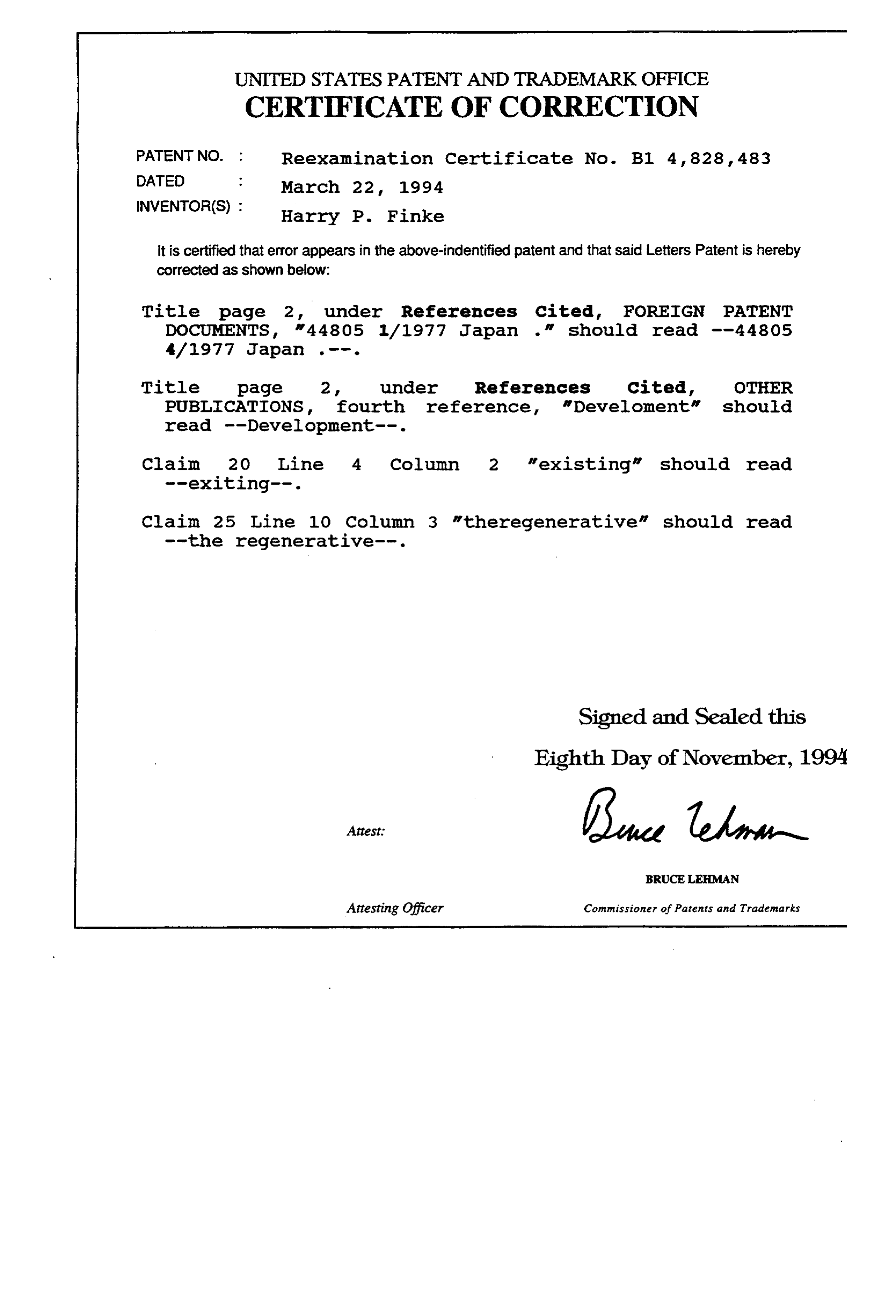
UNITED STATES PATENT AND TRADEMARK OFFICE
CERTIFICATE OF CORRECTION
PATENT NO. : Reexamination Certificate No. B1 4, 828, 483
INVENTOR(S) : Harry P. Finke it is certified that error appears in the above-indentified patent and that said Letters Patent is hereby corrected as shown below:
Title page 2, under References cited, FOREIGN PATENT
Title page 2. under References Cited, OTHER PUBLICATIONS, fourth reference Develoment" should read --Development--.
Claim 20 Line 4 Column 2 "existing" should read
Claim 25 Line 10 Column 3 "theregenerative" should read
Signed and Sealed this
Eighth Day of November, 1994
BRUCELEMAN
Attesting Officer Commissioner of Patents and Trademarks
Page 10
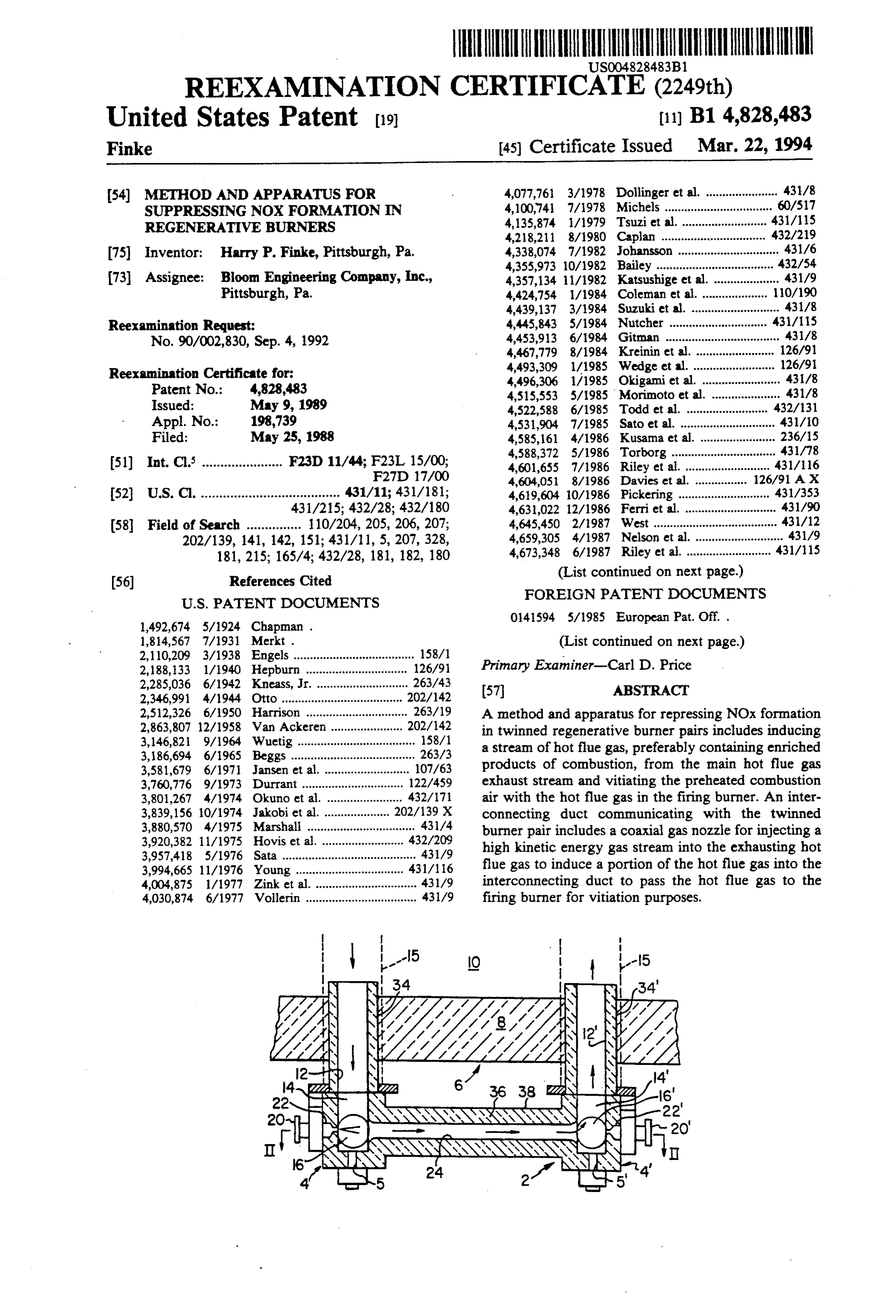
REEXAMINATION CERTIFICATE (2249th)
United States Patent (19) (11) B1 4,828,483 Finke 45 Certificate Issued Mar. 22, 1994 (54) METHOD AND APPARATUS FOR 4,077,761 3/1978 Dollinger et al. ...................... 431/8 SUPPRESSING NOXFORMATION IN 4,100,741 7/1978 Michels .............. ... 60/517 REGENERATIVE BURNERS 4,135,874 1/1979 Tsuzi et al.. 431/15 4,218,211 8/1980 Caplan ....... 432/219 (75 Inventor: Harry P. Finke, Pittsburgh, Pa. 4,338,074 7/1982 Johansson ............................... 431/6 4,355,973 10/1982 Bailey ................. ... 432/54 73) Assignee: Bloom Engineering Company, Inc., 4,357,134 11/1982 Katsushige et al. .................... 431/9 Pittsburgh, Pa. 4,424,754 1/1984 Coleman et al........ ... 110/190 4,439,137 3/1984 Suzuki et al. ........................... 431/8
Reexamination Request: 4,445,843 5/1984 Nutcher ............. 431/15 No. 90/002,830, Sep. 4, 1992 4,453,913 6/1984 Gitman ................................... 431/8 4,467,779 8/1984 Kreinin et al. . ... 126/91 aminati 4,493,309 1/1985 Wedge et al....... ... 126/9
4,496,306 1/1985 Okigami et al. ... 431/8
Issued: May 9, 1989 4,515,553 5/1985 Morimoto et al.
Appl. No.: 198,739 4,531,904 7/1985 Sato et al. ...... .431/10 Fied: May 25, 1988 4,585,161 4/1986 Kusama et al. ... 236/15 o o 4,588,372 5/1986 Torborg ......... ... 431/78 51) Int. Cl....................... F23D 11/44; F23L 14: 4,601,655 7/1986 Riley et al. .......................... 431/16 F27D 17/00 4,604,051 8/1986 Davies et al. . ... 126/91 AX 52 U.S. C. ...................................... 431/11; 431/181; 4,619,604 i0/1986 Pickering ............................ 431/353 431/215; 432/28; 432/180 4,631,022 12/1986 Ferri et al. . ... 431/90 58 Field of Search ............... 110/204, 205, 206, 207; 4,645,450 2/1987 West .......... ... 43/12 202/139, 141, 142, 151; 431/11, 5, 207, 328, 4,659,305 4/1987 Nelson et al. ........................... 431/9 181, 215; 165/4; 432/28, 181, 182, 180 4,673,348 6/1987 Riley et al. .......................... 431/15 (56) References Cited (List continued on next page.)
1,492,674 5/1924 Chapman. 0141594 5/1985 European Pat. Off. . 1,814,567 7/1931 Merkt . (List continued on next page.) 2,110,209 3/1938 Engels ..................... was a v 158/1 2,188,133 1/1940 Hepburn. ... 126/91 Primary Examiner-Carl D. Price 2,285,036 6/1942 Kneass, Jr. . ... 263/43 2,346,991 4/1944 Otto ........... 202712 (57) ABSTRACT
"E.E. A method and apparatus for repressing NOx formation 3,146,821 9/1964 Wuetig ... ... 158/ in twinned regenerative burner pairs includes inducing 3,186,694 6/1965 Beggs ......... - P - 263/3 a stream of hot flue gas, preferably containing enriched 3,581,679 6/1971 Jansen et al. ... 107/63 products of combustion, from the main hot flue gas 3,760,776 9/1973 Durrant ......... . . 122/459 exhaust stream and vitiating the preheated combustion
3,801,267 4/1974. Okuno et air with the hot flue gas in the firing burner. An inter
43A4 connecting duct communicating with the twinned
3,920,382 11/1975 Hovis et al. 432/209 burner pair includes a coaxial gas nozzle for injecting a 3,957,418 5/1976 Sata ... ... 431 /9 high kinetic energy gas stream into the exhausting hot 3,994,665 11/1976 Young ... . . 431/16 flue gas to induce a portion of the hot flue gas into the 4,004,875 l/1977 Zink et al. ............................... 431/9 interconnecting duct to pass the hot flue gas to the 4,030,874 6/1977 Vollerin .................................. 431/9 firing burner for vitiation purposes.
Page 11
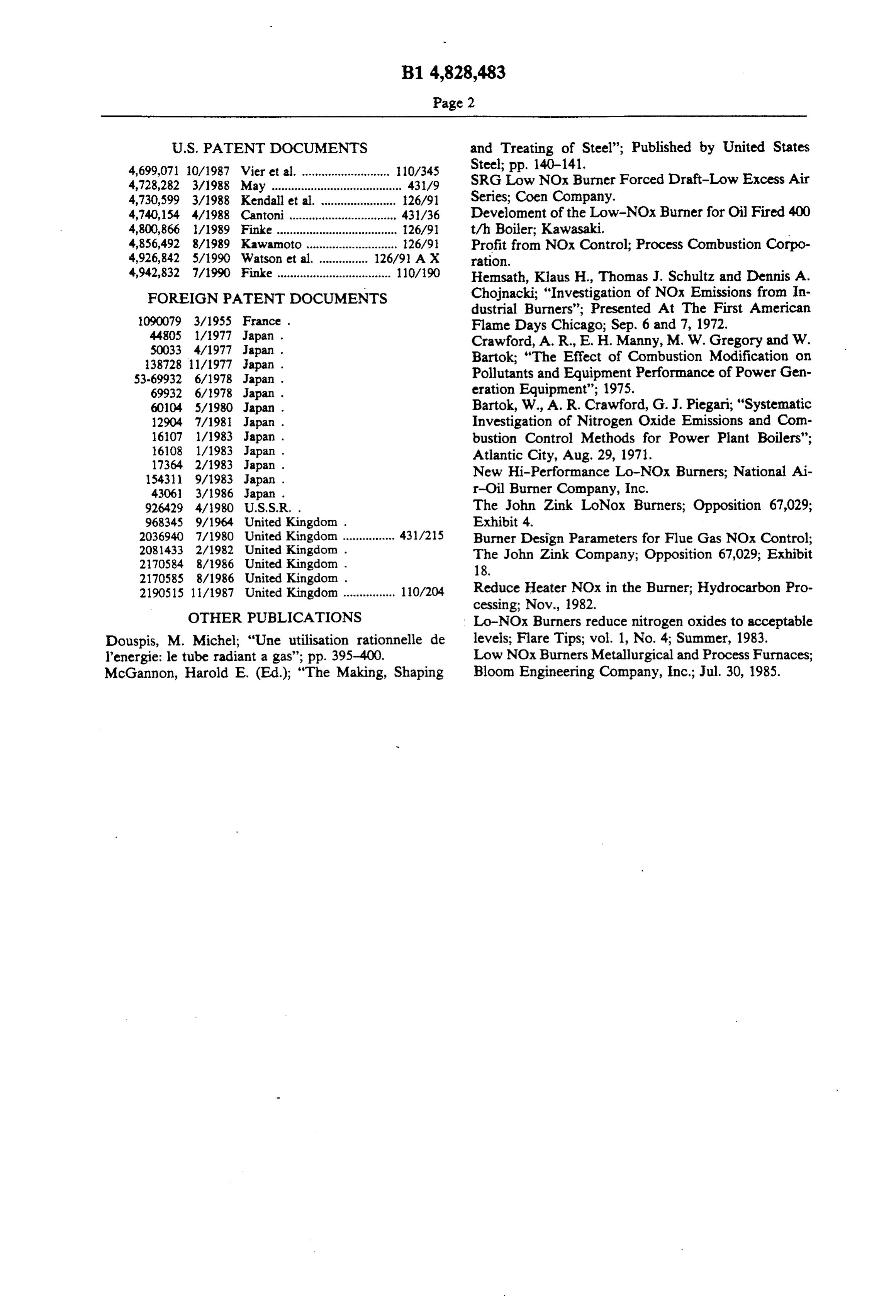
4,699,071 10/1987 Vier et al. ........................... 10/345 Steel; pp. 140-141.
4,728,282 3/1988 May ........................................ 431/9 SRG Low NOx Burner Forced Draft-Low Excess Air 4,730,599 3/1988 Kendall et al. ... 126/91 Series; Coen Company.
4,740,154 4/1988 Cantoni ............. ... 43/36 Develoment of the Low-NOx Burner for Oil Fired 400 4,800,866 l/1989 Finke ..................................... 126/91 t/h Boiler; Kawasaki.
4,856,492 8/1989 Kawamoto............................ 26/91 Profit from NOx Control; Process Combustion Corpo 4,926,842 5/1990 Watson et al. 126/91 AX ration.
4,942,832 7/1990 Finke ................................... 110/90 Hemsath, Klaus H., Thomas J. Schultz and Dennis A. FOREIGN PATENT DOCUMENTS Chojnacki; "Investigation of NOx Emissions from In
dustrial Burners'; Presented At The First American
Flame Days Chicago; Sep. 6 and 7, 1972.
Crawford, A. R., E. H. Manny, M. W. Gregory and W.
138728 11/1977 Japan. Bartok; “The Effect of Combustion Modification on 53-69932 6/1978 Japan. Pollutants and Equipment Performance of Power Gen 69932 6/1978 Japan. eration Equipment"; 1975.
60104 5/1980 Japan. Bartok, W., A. R. Crawford, G. J. Piegari; "Systematic 12904 7/1981 Japan . Investigation of Nitrogen Oxide Emissions and Com 16107 1/1983 Japan. bustion Control Methods for Power Plant Boilers'; 16108 1/1983 Japan . Atlantic City, Aug. 29, 1971. 17364 2/1983 Japan . New Hi-Performance Lo-NOx Burners; National Ai
43061 3/1986 Japan. r-Oil Burner Company, Inc.
92.6429 4/980 U.S.S.R. . The John Zink LoNox Burners; Opposition 67,029; 968345 9/1964 United Kingdom . Exhibit 4.
2036940 7/1980 United Kingdom ................ 431A215 Burner Design Parameters for Flue Gas NOx Control; 2081433 2/1982 United Kingdom . The John Zink Company; Opposition 67,029; Exhibit 2170584 8/1986 United Kingdom . 18.
2190515 11/1987 United Kingdom ................ 10/204 Reduce Heater NOx in the Burner; Hydrocarbon Pro cessing; Nov., 1982.
OTHER PUBLICATIONS Lo-NOx Burners reduce nitrogen oxides to acceptable Douspis, M. Michel; “Une utilisation rationnelle de levels; Flare Tips; vol. 1, No. 4; Summer, 1983. l'energie: le tube radiant a gas'; pp. 395-400. Low NOx Burners Metallurgical and Process Furnaces; McGannon, Harold E. (Ed.); "The Making, Shaping Bloom Engineering Company, Inc.; Jul. 30, 1985.
Page 12
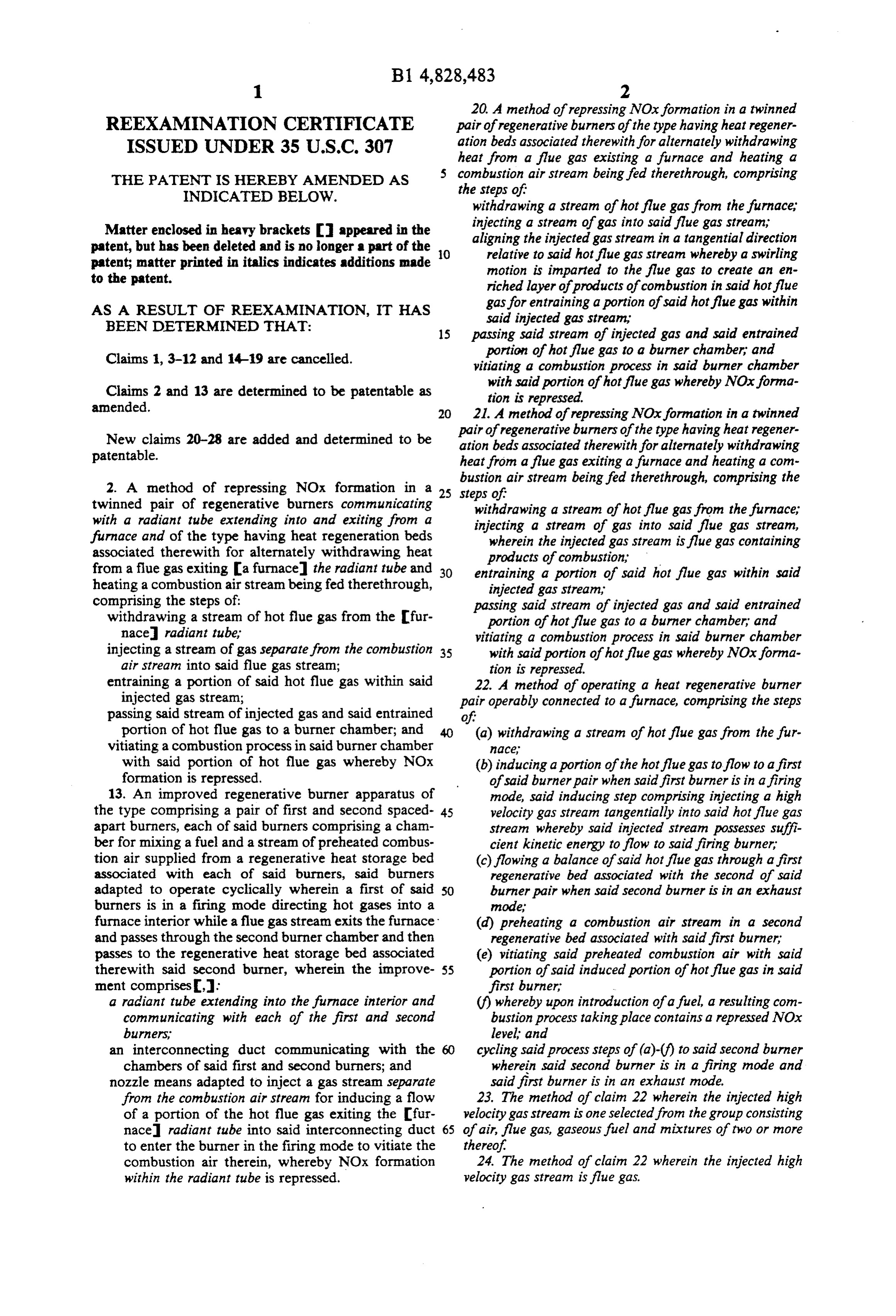
20. A method of repressing NOx formation in a twinned
REEXAMINATION CERTIFICATE pair of regenerative burners of the type having heat regener ISSUED UNDER 35 U.S.C. 307 ation beds associated therewith for alternately withdrawing heat from a flue gas existing a furnace and heating a
THE PATENT IS HEREBY AMENDED AS 5 combustion air stream being fed therethrough, comprising INDICATED BELOW. the steps of withdrawing a stream of hot flue gas from the furnace,
Matter enclosed in heavy brackets I appeared in the injecting a stream of gas into said flue gas stream, patent, but has been deleted and is no longer a part of the aligning the injected gas stream in a tangential direction patent; matter printed in italics indicates additions made O relative to said hot flue gas stream whereby a swirling to the patent. motion is imparted to the flue gas to create an en riched layer of products of combustion in said hot flue
AS A RESULT OF REEXAMINATION, IT HAS gas for entraining a portion of said hot flue gas within BEEN DETERMINED THAT: said injected gas stream 15 passing said stream of injected gas and said entrained
Claims 1, 3-12 and 14-9 are cancelled. portion of hot flue gas to a burner chamber, and vitiating a combustion process in said burner chamber
Claims 2 and 13 are determined to be patentable as with said portion of hot flue gas whereby NOx forma amended.
tion is repressed.
21. A method of repressing NOx formation in a twinned
New claims 20-28 are added and determined to be pair of regenerative burners of the type having heat regener patentable. ation beds associated therewith for alternately withdrawing heat from a flue gas exiting a furnace and heating a con bustion air stream being fed therethrough, comprising the 2. A method of repressing NOx formation in a 25 steps of twinned pair of regenerative burners communicating withdrawing a stream of hot flue gas from the furnace, with a radiant tube extending into and exiting from a injecting a stream of gas into said flue gas stream, furnace and of the type having heat regeneration beds wherein the injected gas stream is flue gas containing associated therewith for alternately withdrawing heat products of combustion from a flue gas exiting a furnace the radiant tube and 30 entraining a portion of said hot flue gas within said heating a combustion air stream being fed therethrough, injected gas stream, comprising the steps of: passing said stream of injected gas and said entrained withdrawing a stream of hot flue gas from the fur portion of hot flue gas to a burner chamber, and nace radiant tube, vitiating a combustion process in said burner chamber injecting a stream of gas separate from the combustion 35 with said portion of hot flue gas whereby NOx forma air stream into said flue gas stream; tion is repressed.
entraining a portion of said hot flue gas within said 22. A method of operating a heat regenerative burner injected gas stream; pair operably connected to a furnace, comprising the steps passing said stream of injected gas and said entrained of portion of hot flue gas to a burner chamber; and 40 (a) withdrawing a stream of hot flue gas from the fur vitiating a combustion process in said burner chamber nace with said portion of hot flue gas whereby NOx (b) inducing a portion of the hot flue gas to flow to a first formation is repressed. of said burner pair when said first burner is in a firing 13. An improved regenerative burner apparatus of mode, said inducing step comprising injecting a high the type comprising a pair of first and second spaced 45 velocity gas stream tangentially into said hot flue gas apart burners, each of said burners comprising a cham stream whereby said injected stream possesses suffi ber for mixing a fuel and a stream of preheated combus cient kinetic energy to flow to said firing burner tion air supplied from a regenerative heat storage bed (c) flowing a balance of said hot flue gas through a first associated with each of said burners, said burners regenerative bed associated with the second of said adapted to operate cyclically wherein a first of said 50 burner pair when said second burner is in an exhaust burners is in a firing mode directing hot gases into a mode, furnace interior while a flue gas stream exits the furnace (d) preheating a combustion air stream in a second and passes through the second burner chamber and then regenerative bed associated with said first burner, passes to the regenerative heat storage bed associated (e) vitiating said preheated combustion air with said therewith said second burner, wherein the improve 55 portion of said induced portion of hot flue gas in said ment comprises, first burner, a radiant tube extending into the furnace interior and (f) whereby upon introduction of a fuel, a resulting com communicating with each of the first and second bustion process taking place contains a repressed NOx burners, level and an interconnecting duct communicating with the 60 cycling said process steps of (a)-(f) to said second burner chambers of said first and second burners; and wherein said second burner is in a firing mode and nozzle means adapted to inject a gas stream separate said first burner is in an exhaust mode. from the combustion air stream for inducing a flow 23. The method of claim 22 wherein the injected high of a portion of the hot flue gas exiting the fur velocity gas stream is one selected from the group consisting nace radiant tube into said interconnecting duct 65 of air, flue gas, gaseous fuel and mixtures of two or more to enter the burner in the firing mode to vitiate the thereof combustion air therein, whereby NOx formation 24. The method of claim 22 wherein the injected high within the radiant tube is repressed. velocity gas stream is flue gas.
Page 13
25. An improved regenerative burner apparatus of the flue gas whereby a layer of highly enriched products of type comprising a pair of first and second spaced-apart combustion 27. The gas is entrained in said gas stream.
apparatus of claim 25 wherein each of said burners, each of said burners comprising a chamber for burner chambers includes a plurality of fuel inlet nozzles mixing a fuel and a stream of preheated combustion air arranged tangentially relative supplied from a regenerative heat storage bed associated whereby a swirling motion is toimparted a bore of said chamber to gases flowing with each of said burners, said burners adapted to operate therein to improve mix of the fuel, preheated combustion cyclically, wherein a first of said burners is in a firing node air and vitiating hot flue gas. directing hot gases into a furnace interior while a flue gas 28. A method of repressing NOx formation in a twinned stream exits the furnace and passes through the second 10 pair of regenerative burners of the type having heat regener burner chamber and then passes to theregenerative heat ation beds associated therewith for alternately withdrawing storage bed associated therewith said second burner, heat from a flue gas exiting a furnace and heating a com wherein the improvement comprises, bustion air stream being fed therethrough, comprising the an interconnecting duct communicating with the cham steps of bers of said first and second burners and 15 withdrawing a stream of hot flue gas from the furnace nozzle means adapted to inject a gas stream for inducing injecting a stream of gas separate from the combustion a flow of a portion of the hot flue gas exiting the air stream into said flue gas stream, said injected gas furnace into said interconnecting duct to enter the stream being one selected from the group consisting of flue gas containing products of combustion, gaseous burner in the firing mode to vitiate the combustion air 20 fuel, and mixtures thereof therein, whereby NOx formation is repressed entraining a portion of said hot flue gas within said said nozzle means including a nozzle associated with injected gas stream each of said burner chambers, each nozzle having an passing said stream of injected gas and said entrained orifice aligned substantially coaxially with said inter portion of hot flue gas to a burner chamber, and connecting duct. 25 vitiating a combustion process in said burner chamber 26. The apparatus of claim 25 wherein the interconnect with said portion of hot flue gas whereby NOx forma ing duct is aligned tangentially relative to each of said tion is repressed.
burner chambers to impart a swirling motion in said hot
Provenance
- Collection
- Cited prior art
- Original PDF
- patentimages.storage.googleapis.com →
- Filed
- 1988-05-25
- Pages
- 13
- Method
- pdftotext (the PDF's own text layer) + pdftoppm 300dpi page scans
- Source
- Google Patents bibliographic record
- Granted
- 1989-05-09
- Inventors
- Harry P. Finke; Bloom Engineering Co Inc
- Transcribed from
- patentimages.storage.googleapis.com →