patent · US3207493
Regenerative furnaces
21 September 1965
Page 1
Drawing sheet — no readable text.
Page 2
Drawing sheet — no readable text.
Page 3
Drawing sheet — no readable text.
Page 4
United States Patent Office 3,207,493 Patented Sept. 21, 1965
the invention, given by way of example only and without 3,207,493 limitation of the scope of the invention, which is defined
REGENERATIVE FURNACES in the hereto appended claims, of these drawings:
John Arthur Swain, Birmingham, England, assignor to
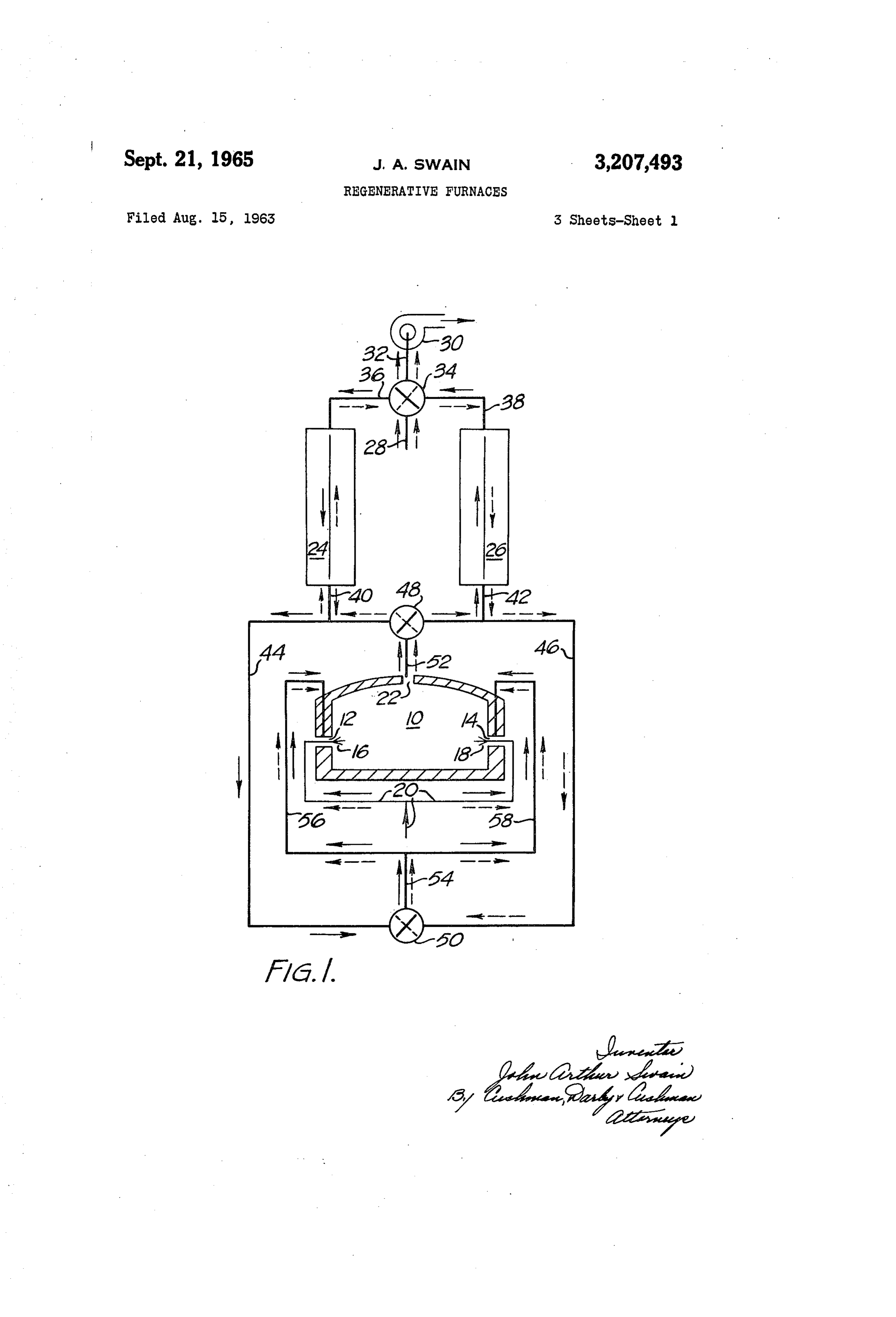
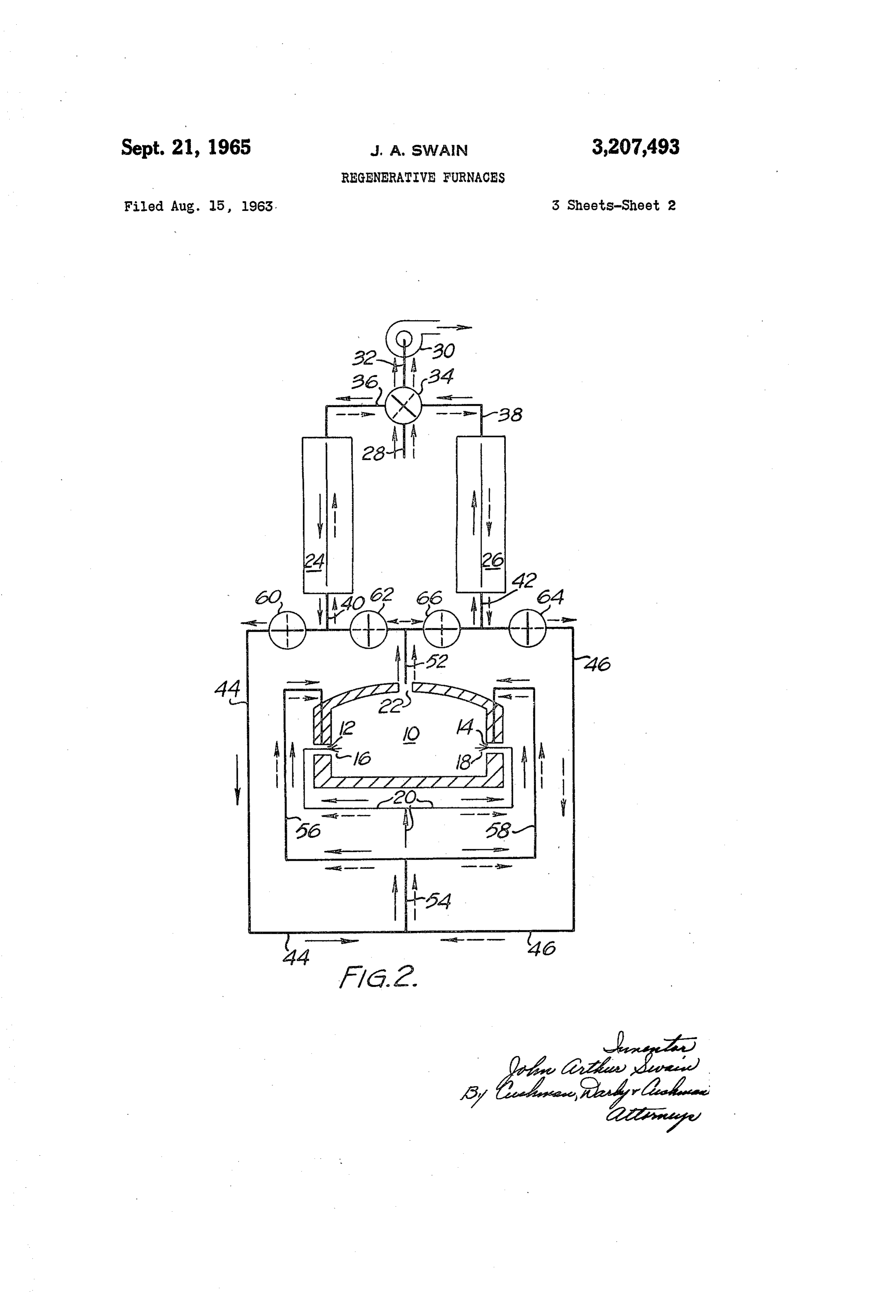
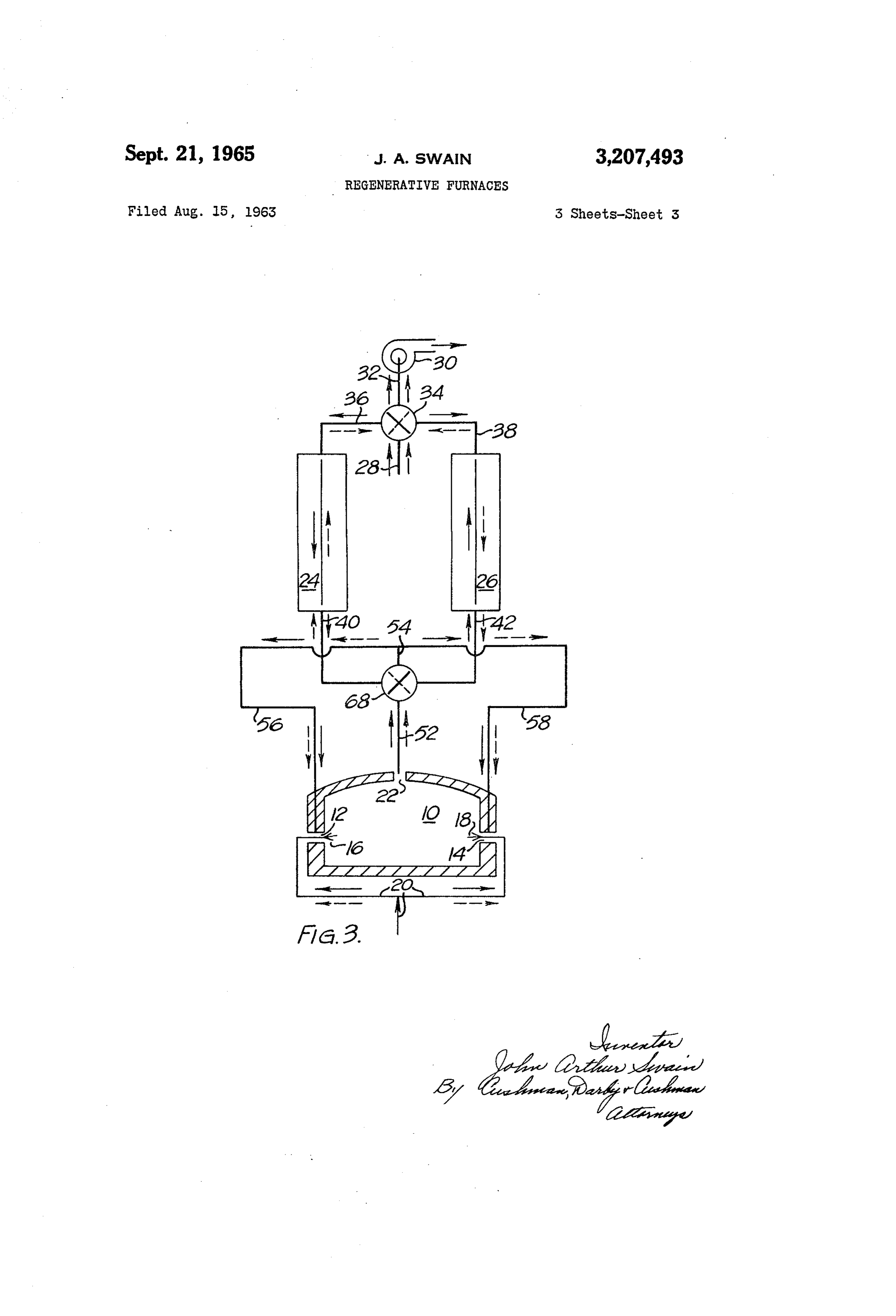
I candescent Limited, Smethwick, England, a corpora 5 firstFIGURE 1 is a diagrammatic representation of the embodiment, the furnace chamber being shown in tion of the United Kingdom Schematic vertical section; and Filed Aug. 15, 1963, Ser. No. 302,337 FIGURES 2 and 3 are similar representations of the Claims priority, application Great Britain, Aug. 17, 1962, 31,683/62 Second and third embodiments respectively.
4 Claims. (C. 263-15) In these drawings:
O Fuel supply lines are represented in thin line, and duct
This invention relates to regenerative furnaces, in which ing carrying air and combustion products in heavy line; the combustion air (or oxygen or oxygen-enriched air), in one phase of the reversing cycle, the positions of the hereinafter referred to for brevity as “air,' is preheated reversing valves, which are of the butterfly type, and the by paired regenerators which alternately receive heat arrows indicating direction of flow, are in full line, and from the combustion products and reject heat to the com 5 in the other phase of the cycle in dotted line; and the sev bustion air. eral reversing valves are operatively interconnected (me In hitherto conventional practice, such furnaces have chanically or otherwise) for synchronisation, by means had two sets of burners, usually disposed on opposite (not illustrated) giving the apropriate phase relationships. sides of the working chamber of the furnace, to which sets In these drawings, elements common to more than one of burners the preheated air and fuel for combustion are 20 of the embodiments illustrated, are identified by the same alternately fed, the combustion products being taken off reference characters.
alternately from one and the other of two outlets, which, Referring to FIGURE 1, the furnace chamber 10 has in practice are usually the same as the preheated air inlets combustion air inlets 12, 14 on each side, in which are containing the burners. disposed burners 6, 18, continuously supplied with fuel Such an arrangement entails cyclical reversal of the 25 (oil or gas) by pipes 20. In the roof of the furnace is an flow of combustion products from one side of the furnace outlet 22 through which the hot combustion products are to the other and consequent uneven heating of the charge eXtracted.
in the furnace chamber. Moreover, since in each half The combustion air is heated by regenerators 24, 26 cycle one set of burners is inactive, each set of burners which operate alternately. Cold air enters through a pipe (and the ducting leading thereto), must be capable of 30 28 and exhaust gases are extracted by a blower 30 from a handling twice as much air and fuel as they would have pipe 32. A four-port reversing valve 34 is connected to to if all the burners were operative continuously. pipes 28, 32 and also by pipes 36, 38 respectively to the The principal aim of the invention is to provide means "cold' ends of the regenerators 24, 26. As shown in the enabling all the burners (on both sides of the furnace drawing in one (the first) phase of the regenerative cycle chamber) to operate continuously and to eliminate cycli 35 the valve 34 connects pipe 28 to pipe 36 and pipe 32 to cal reversal of flow of combustion products within the pipe 38, these connections being reversed in the succeed furnace chamber. ing phase.
An object of this invention is a regenerative furnace, . The "hot' ends of the regenerators 24, 26 are respec whose chamber had two (or two sets of) combustion air tively connected by branch pipes 40, 42 with pipes 44 and inlets and a separate outlet for combustion products, and 40 46 which are alternately connected by a three-port revers which is provided with reversing valve means, additional ing valve 48 with a pipe 52 leading from the exhaust out to and synchronised with the reversing valve for alter let 22 of the furnace.
nately connecting the cold ends of the regenerators with Pipes 44, 46 are likewise alternately connected by a the cold air supply and with the exhaust flue, and opera three-port reversing valve 50 with a pipe 54 having two tive to connect the hot end of one regenerator alternately 45 branches 56, 58 connected to the combustion air inlets with the combusition air inlets and the hot end of the 12, 14 of the furnace.
other regenerator with the combustion product outlet of The reversing valves 34, 48, 50 are mechanically or the furnace chamber. otherwise (e.g. pneumatically, hydraulically or electrical In one preferred form of construction the combustion ly) synchronized in such a way that in the first phase of product outlet of the furnace chamber is connected by a 50 the regenerative cycle, regenerator 24 is connected by pipes branched duct with corresponding ends of both regenera 40, 44 and the valve 50 with pipes 54, 56, 58 and regen tors and a three-port reversing valve is situated at the erator 26 is connected by pipes 42, 46 and the valve 48, junction of the branches, while preheated air inlets on with the pipe 52. In the succeeding (or second) phase each side of the furnace are connected to one port of a these connections are reversed. second three-port reversing valve whose other two ports 55 The embodiment illustrated in FIGURE 2 differs from communicate respectively with one and the other of the that of FIGURE 1 only in the following respect: regenerators, at the same end as is connected to the afore The three-port reversing valves 48, 50 of FIGURE 1 said branched duct, the two reversing valves being ap are replaced by two pairs of two-port reversing valves 60, propriately synchronised. 62 and 66, 64. Valves 60, 62 are placed in the run of Alternatively, each of the three-port reversing valves 60 pipe 44 on opposite sides of its junction with pipe 40 and may be replaced by a pair of two-port reversing valves, are antiphased as shown; and valves 64, 66 are similarly all four two-port valves being appropriately synchronised placed in the run of pipe 46 with respect to its junction with the required phase relationships. with pipe 42 and are likewise antiphased. It is possible to replace the two three-port reversing Between valves 62 and 66, pipes 44, 46 are both joined valves by a single four-port reversing valve. 65 directly to pipe 52, and the portions of pipes 44, 46, ex In each form of construction described above, the pre tending beyond valves 60 and 64 respectively are both heated air inlets are provided with burners to which a joined directly to pipe 54.
suitable fuel, e.g. a gas, is continuously supplied by suit In the embodiment of FIGURE 3, the two three-port able ducting. reversing valves 48, 50 of FIGURE 1 are replaced by a The objects and nature of the invention will be better 70 single four-port reversing valve 68, of which two opposite understood from the following description, with reference ports are directly connected to pipes 40 and 42 respec to the accompanying drawings of three embodiments of tively and the two other opposite ports are respectively
Page 5
connected to pipe. 52 and pipe 54, the latter being di a cold end for receiving cold gaseous oxydant from said rectly joined as in FIGURE 1 to pipes 56 and 58 and the Source; first reversing valve means associated with the pipes 44, 46 are eliminated. In the first phase of the cycle, cold ends of said regenerators operative in a first position valve 68 connects regenerator 24 via pipes 54, 56 and 58 to simultaneously connect the cold end of the first re with both the furnace inlets 12, 14 and connects regenera generator to said source of cold oxydant and the cold end tor 26, via pipe 52 with the furnace outlet 22, these con of the Second regenerator to the inlet of said exhaust nections being reversed in the second phase of the cycle. blower and operative in a second position to simulta It will be evident that, in each of the three embodi neously connect the cold end of the second regenerator to ments illustrated, the arrangement of reversing valves and said source and the cold end of said first regenerator to pipes, while effecting the normal regenerative cycle, by O the inlet of said exhaust blower; second reversing valve which the regenerators alternately receive and reject heat, means downstream of said single outlet associated with ensures that regeneratively preheated air is continuously the hot ends of said regenerators operative in a first posi Supplied to the burners on both sides of the furnace, at tion to simultaneously connect the hot end of the first re the same time eliminating the need for a reversing valve generator to both said oxydant inlets and the hot end of in the fuel supply system of the burners. 5 the Second regenerator to said single outlet and operative It is to be understood that within the scope of the in in a second position to simultaneously connect the hot vention as defined in the hereto appended claims, any or end of the Second regenerator to both said oxydant inlets all such modifications, variations or additions of or to and the hot end of the first regenerator to said single out what has been hereinbefore described as are within the let.
competence of those skilled in the art may be made. For 20 2. A regenerative furnace as in claim 1 wherein said example, the constructional details of the furnace, the Second reversing valve means comprises two synchronized regenerators, the ducting, the burners, the reversing valves three-port valves, each valve having two ports connected and their synchronising means, and the like may be of respectively with the hot end of one and the other of the any suitable conventional design, and for this reason regenerators, and the third ports of the three-port valves these details have not been illustrated or described. 25 being connected respectively with both said oxydant in Again, means, including additional valving, may be pro lets and with said single outlet.
vided for re-circulating an adjustable proportion of cooled 3. A regenerative furnace as in claim 1 wherein said exhaust gases from the outlet to the inlet of the heat-re Second reversing valve means comprises a pair of syn ceiving regenerator, with or without the addition of an chronized two-port valves associated with each regenera adjustable proportion of cold or regeneratively preheated 30 tor, both of the valves of each pair having one port con air (or gaseous oxidant) for completing the combustion nected with the hot end of the associated regenerator, or unburnt or partially burnt combustibles in the gases and the Second port of one valve of each pair being con issuing from the furnace outlet. Moreover, the invention nected with both of said oxydant inlets, the second port is applicable to furnaces, such as rotary hearth furnaces of the other valve of each pair being connected with said or those through which the charge is continuously or in 35 single outlet.
termittently propelled in a straight line, by pusher means 4. A regenerative furnace as in claim 1 wherein said or/and by gravity, having more than one pair of regenera Second reversing valve means comprises a single four tors associated with different zones of the furnace. port valve having one port connected with said single out What is claimed is: let, one port connected with both of said oxydant inlets, 1. A regenerative furnace comprising: a furnace cham 40 and two ports connected respectively with the hot end ber having opposed side walls, end walls and a roof, said of Said first and second regenerators. opposed side walls having inlets therein for the intro duction of regeneratively preheated gaseous oxydant into References Cited by the Examiner Said chamber, said chamber having a single outlet for 45 UNITED STATES PATENTS combustion products separate from said inlets; an ex 1,925,941 9/33 Simpson --------------- 263-15 haust blower having an inlet and an outlet; fluid fuel 2,429,880 10/47 Hays -------------- 263-15. burner means disposed in each of said oxydant inlets; 2,574,740 11/51 Hartman ------------ 263-15 means for continuously supplying fluid fuel to all of said 2,655,363 10/53 Roof ----------------- 263-15 burner means; a source of cold gaseous oxydant; first and 50 2,288,491 6/42 Seil ------------------- 263-15. Second regenerators for alternately absorbing heat from hot combustion products and giving up heat to cold gase WILLIAM F. O'DEA, Acting Primary Examiner. Qus oxydant, each of said regenerators having a hot end for receiving combustion gases from said single outlet and CHARLESSUKALO, Examiner.
Provenance
- Collection
- Cited prior art
- Original PDF
- patentimages.storage.googleapis.com →
- Filed
- 1963-08-15
- Pages
- 5
- Method
- pdftotext (the PDF's own text layer) + pdftoppm 300dpi page scans
- Source
- Google Patents bibliographic record
- Granted
- 1965-09-21
- Inventors
- Swain John Arthur; INCANDESCENT Ltd
- Transcribed from
- patentimages.storage.googleapis.com →