patent · US4355973
Radiant heating apparatus
26 October 1982
Page 1 — bibliographic record
United States Patent (19) 11 4,355,973 Bailey 45 Oct. 26, 1982
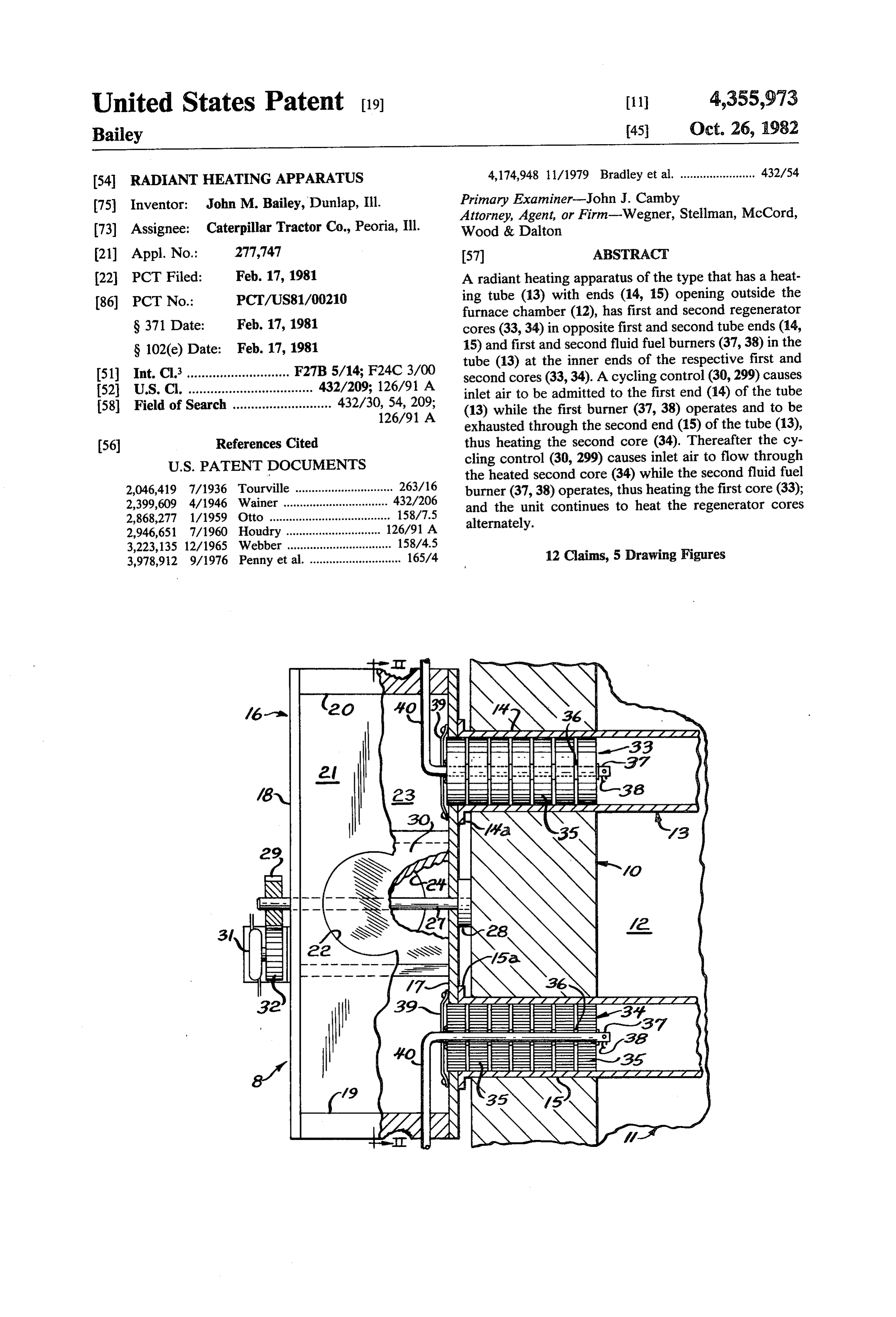
54 RADIANT HEATING APPARATUS 4,174,948 11/1979 Bradley et al. ....................... 432/54 75) Inventor: John M. Bailey, Dunlap, Ill. Primary Examiner-John J. Camby Attorney, Agent, or Firm-Wegner, Stellman, McCord, 73) Assignee: Caterpillar Tractor Co., Peoria, Ill. Wood & Dalton (21) Appl. No.: 277,747 57 ABSTRACT 22, PCT Filed: Feb. 17, 1981 A radiant heating apparatus of the type that has a heat 86 PCT No.: PCT/US81/00210 ing tube (13) with ends (14, 15) opening outside the furnace chamber (12), has first and second regenerator
S371 Date: Feb. 17, 1981 cores (33, 34) in opposite first and second tube ends (14, S 102(e) Date: Feb. 17, 1981 15) and first and second fluid fuel burners (37,38) in the tube (13) at the inner ends of the respective first and (51) Int. Cl. ............................ F27B 5/14; F24C3/00 second cores (33,34). A cycling control (30,299) causes (52) U.S. C. .................................. 432/209; 126/91 A inlet air to be admitted to the first end (14) of the tube 58) Field of Search ........................... 432/30,126/91
A (13) while the first burner (37,38) operates and to be exhausted through the second end (15) of the tube (13), (56) References Cited thus heating the second core (34). Thereafter the cy cling control (30, 299) causes inlet air to flow through
2,046,419 7/1936 Tourville .............................. 263/16 burner (37,38) operates, thus heating the first core (33); 2,399,609 4/1946 Wainer ..... ... 432/206 and the unit continues to heat the regenerator cores 2,868,277 1/1959 Otto .......... ... 158/7.5 alternately.
2,946,651 7/1960 Houdry ..... 126/91 A 3,223,135 12/1965 Webber ... ... 158/4.5 3,978,912 9/1976 Penny et al. ............................ 165/4 12 Claims, 5 Drawing Figures
Page 2
Drawing sheet — no readable text.
Page 3
Drawing sheet — no readable text.
Page 4
Drawing sheet — no readable text.
Page 5
Drawing sheet — no readable text.
Page 6
tion products which heat the first regenerator core as
RADIANT HEATING APPARATUS they pass to the stack.
TECHNICAL FIELD BRIEF DESCRIPTION OF THE DRAWINGS
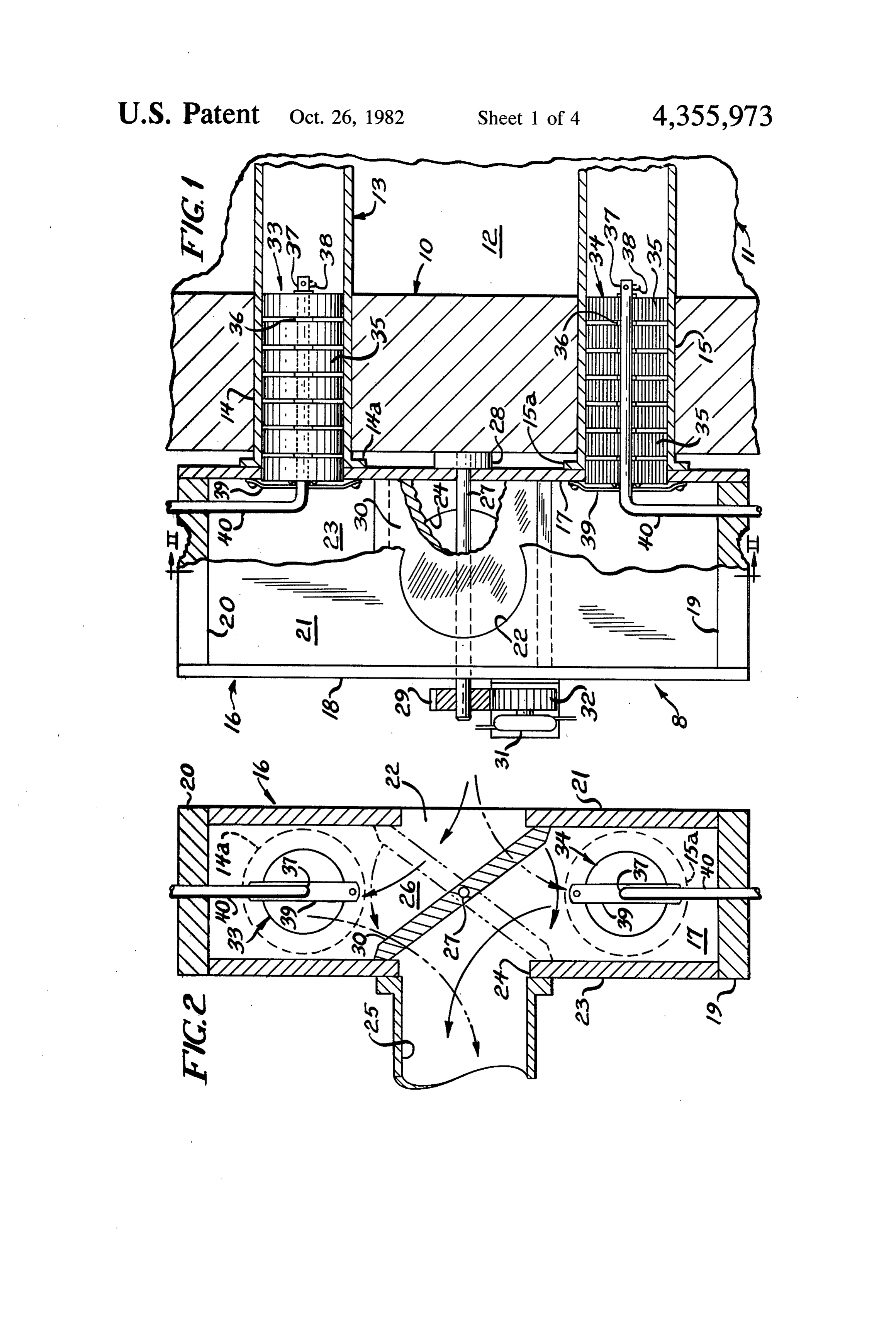
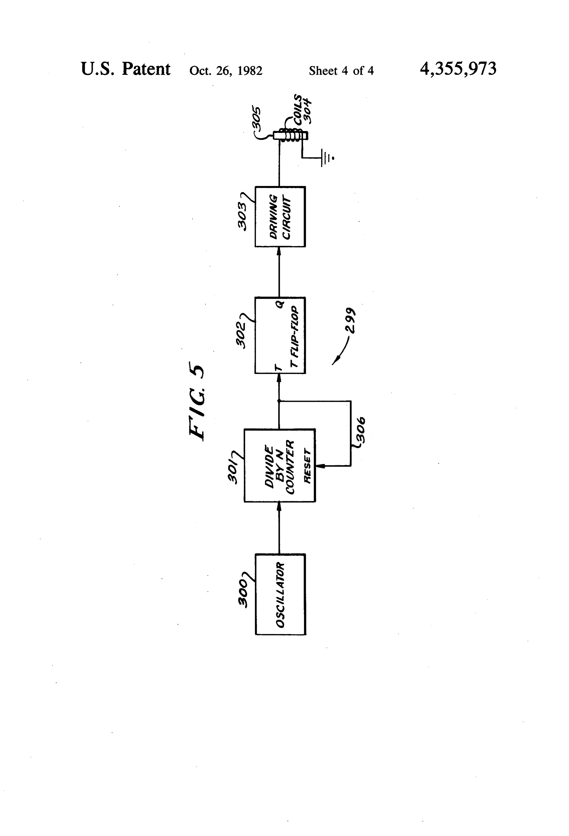
This invention relates to a radiant heating apparatus, 5 FIG. 1 is a fragmentary sectional view of a first em and more particularly to a heating apparatus employing bodiment of a radiant heating apparatus supplied with a radiant heating tube and a regenerator system. the regenerative system of the present invention;
BACKGROUND ART
FIG. 2 is a fragmentary sectional view taken substan tially as indicated along the line II-II of FIG. 1;
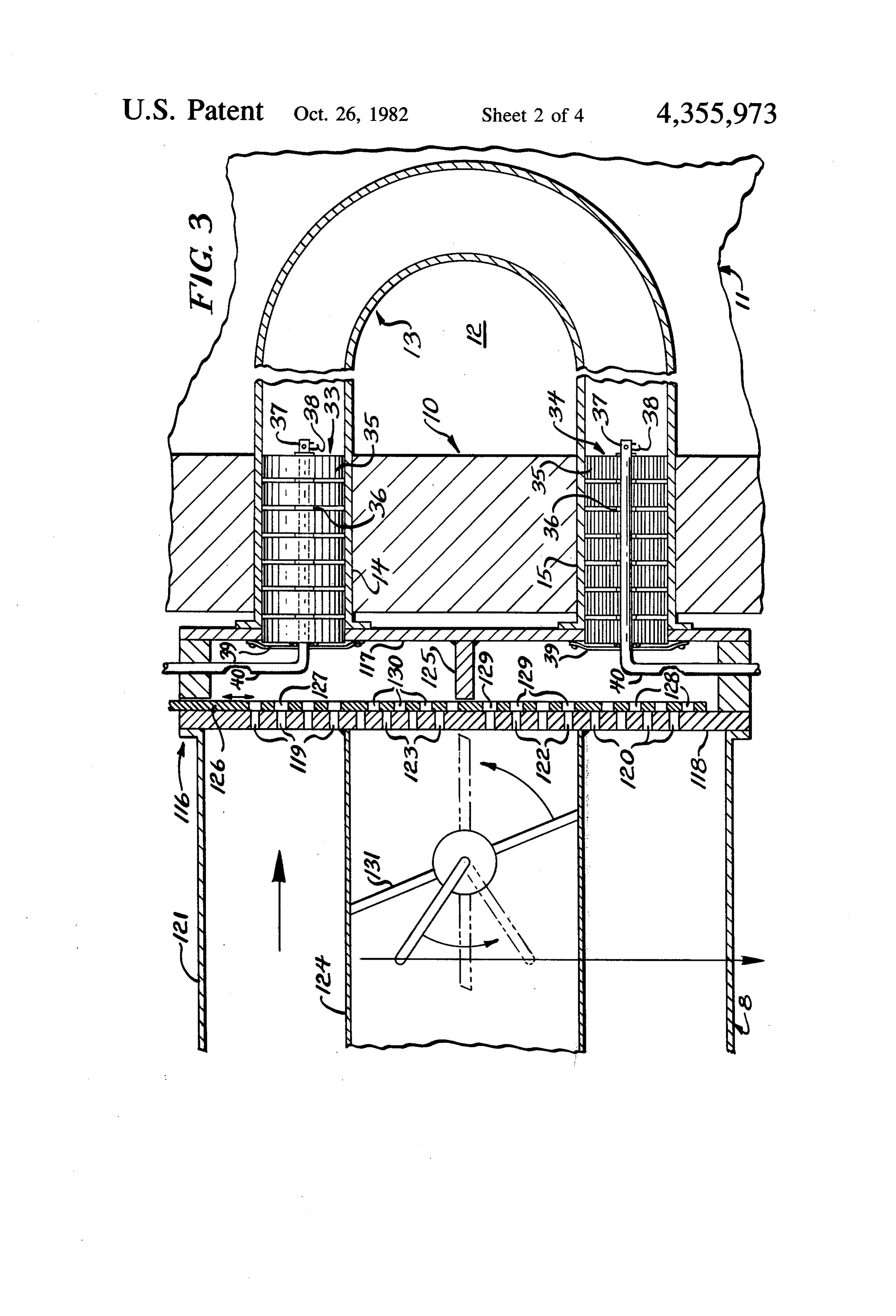
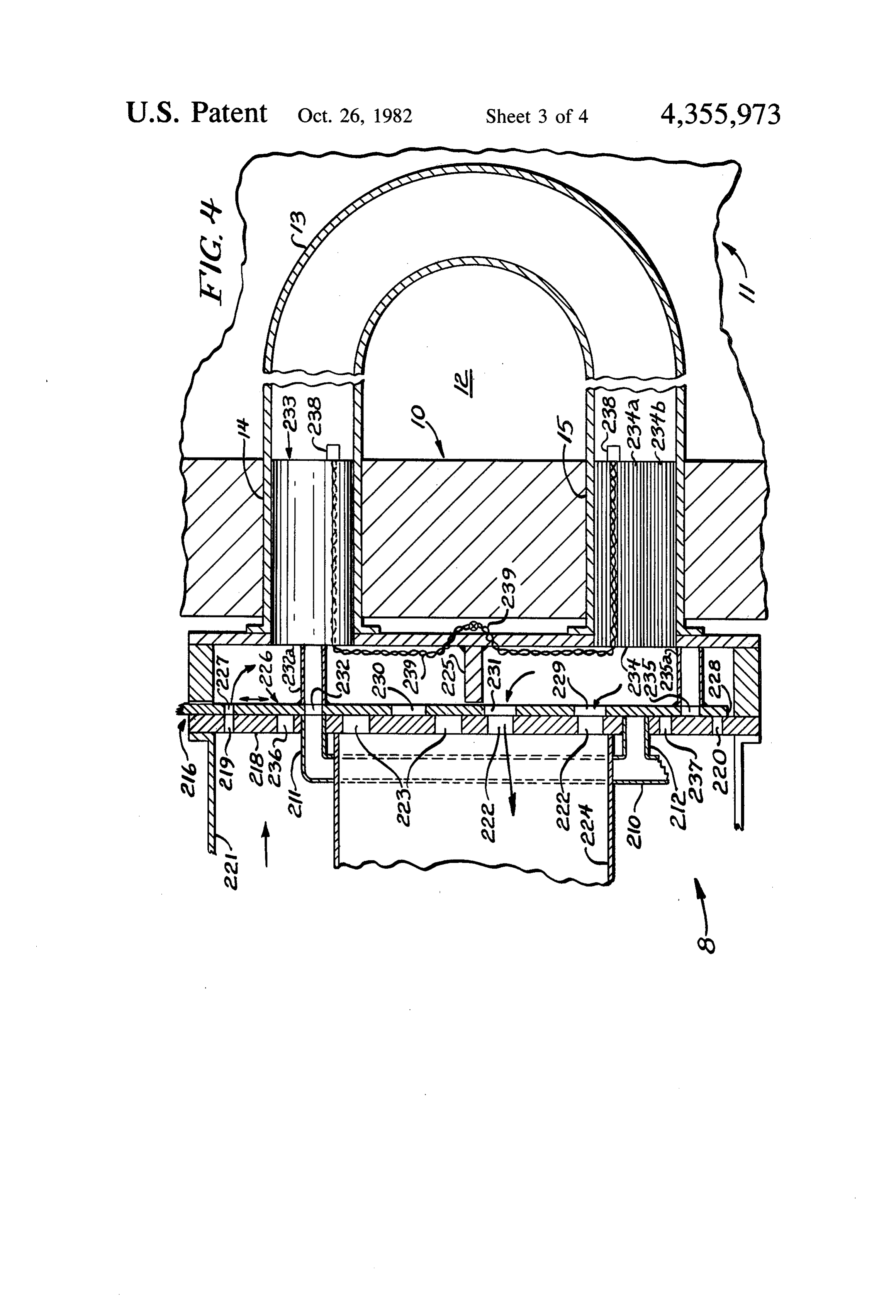
Regenerative heat exchangers and recuperators have 10 FIG. 3 is a fragmentary sectional view of a second been commonly used in high temperature furnaces such embodiment of the invention;
as glass furnaces (Bradley et al. U.S. Pat. No. 4, 174,948), FIG. 4 is a fragmentary sectional view of a third open hearth furnaces (Tourville U.S. Pat, No. embodiment of the invention designed particularly for 2,046,419), and coke ovens (Otto U.S. Pat. No. 15 use with low BTU producer, or coal gas; and 2,868,277). See also Webber U.S. Pat. No. 3,223,135, FIG. 5 is a diagrammatic view of the cycling means which refers to the common practice of cyclically re which controls airflow and combustion. versing the flow of air and the supply of fuel to burners BEST MODE FOR CARRYING OUT THE so that, after one half cycle when the furnace is first INVENTION started up, the combustion air always passes over hot 20 regenerator elements. More recently, regenerative heat Referring to the drawings in detail, and referring first exchangers have been used in gas turbine engines (Pen to FIGS. 1 and 2, a radiant heating apparatus 8 includes ney et al. U.S. Pat. No. 3,978,912). a heavy upright furnace wall, indicated generally at 10 The regenerator of U.S. Pat. No. 3,978,912 was espe which cooperates with an end wall 11 and with four cially engineered for use in automotive gas turbine en other walls (not shown) to define a radiant heating gines, and thus had to be quite compact. Regenerators 25 furnace chamber 12. The walls are all of about the same used in furnaces, on the other hand, have generally been thickness, which may be from about 22.85 to 30.50 cm large and required substantial, heavily insulated regen (9' to 12"), so the chamber 12 is heavily insulated to erators outside the furnace chamber. Such structures suffer are not acceptable in modern manufacturing facilities ber 12minimum may be heat loss. Typically, the furnace cham used for heat treating metal parts, so one where space is at a premium, and where furnaces must of the walls other than
be used for such purposes as heat treating metal parts. heavily insulated, sealed the door wall 10 is provided with a through which articles to
Relatively compact radiant heating furnaces for this purpose are known to the prior art, but applicant knows be heat treated may be introduced to and removed from of no recuperator or regenerator system applicable to the furnace chamber. A U-tube, indicated generally at such furnaces that does not greatly increase the space 35 13, 15 has a first end portion 14 and a second end portion which extend through the furnace wall 10 in spaced occupied by the furnace.
The foregoing illustrates problems of the known relationship the U-tube to one another. As seen in FIGS. 3 and 4, 13 extends a substantial distance into the prior art. Thus, it is apparent that it would be advanta geous to provide an alternative directed to overcoming chamber 12; and a large capacity furnace will be sup-. one or more of the problems set forth above. plied with a series of U-tubes 13, all of which extend through the wall 10 in parallel, spaced relationship to
DISCLOSURE OF THE INVENTION one another. The U-tubes supply radiant heat to the In accordance with the present invention, a radiant furnace chamber 12, and are essentially conventional in heating apparatus is of the type which has walls defin this type of apparatus.
ing a chamber to be heated, a tube in the chamber with 45 The extreme outer ends of the U-tube are provided first and second end portions extending through the with flanges 14a and 15a by means of which the U-tube chamber wall, a fluid fuel burner in the tube, air inlet is secured to an air box, indicated generally at 16. The means through which combustion air, is supplied to the air box 16 has an inner wall 17 and an outer wall 18 burner, and combustion gas outlet means through which are parallel to the furnace wall 10, and end plates which combustion products from the tube pass. The 50 19 and 20. A side wall 21 contains an air inlet opening apparatus is supplied with a regenerator system which 22, while a side wall 23 has an opening 24 which com has first and second regenerator cores in the first and municates with a venting stack 25. Thus, the air inlet second end portions of the tube, and each of the regen opening 22 and the air box 16 provide combustion air erator cores has a large surface area over which gases inlet means.
may flow freely. First and second fluid fuel burners are 55 A throat 26 between the air inlet opening 22 and the immediately adjacent the inner ends of the respective outlet opening 24 is intersected by a shaft 27 which has first and second regenerator cores, and cycling means of one end supported in a bearing 28 mounted upon the the general type discussed in the Webber patent is pro wall 17 and the other end projecting through the wall vided to control airflow and combustion. The cycling 18 and provided with a drive gear 29. Mounted upon means causes air from the inlet means to flow through the shaft 27 is a butterfly valve 30 which may be rotated the first regenerator core and fuel to be supplied only to between the full line position of FIG. 2 and the broken the first fluid fuel burner to operate that burner, thereby line position of FIG. 2 so as to reverse the airflow from producing hot combustion products which heat the the air inlet 22 through the U-tube 13 to the venting second regenerator core as they pass to the stack. The stack 25. When the butterfly valve 30 is in the position cycling means then causes the air from the inlet means 65 illustrated in FIG. 2, airflow is from the inlet means to flow through the heated second regenerator core and through the end 14 of the U-tube, out the end 15 of the fuel to be supplied only to the second fluid fuel burner U-tube and to the venting stack 25. When the butterfly to operate that burner, thereby producing hot combus valve 30 is in the broken line position of FIG. 2, the
Page 7
airflow is from the inlet 22 into the end portion 15 of the FIGS. 3 and 4 as well as to the apparatus of FIG. 1, it U-tube 13, and out through the end portion 14 to the will be described in detail only after the devices of venting stack 25. FIGS. 3 and 4 are described.
As illustrated in FIG. 1, reversible movement of the Turning now to FIG. 3, the apparatus is like that of butterfly valve 30 may conveniently be provided by a 5 FIGS. 1 and 2 except for the air box structure and the reversible electric motor 31 on the shaft of which is a valve arrangement for shifting the flow of inlet air and gear 32 that is in driving engagement with the gear 29 combustion gases to one end portion or the other of the on the butterfly valve shaft 27; although other suitable U-tube 13. Accordingly, much of the structure of FIG. means such as a hydraulic motor or a hydraulic cylinder 3 is not described in detail, but like reference numerals may be used. Alternatively, since a radiant heating ap 10 are applied to those components which are the same as paratus has a large number of U-tubes 13 arranged side those in FIG. 1.
by side, and there is an air box and butterfly valve for In the present apparatus, an air box, indicated gener each such U-tube, the shaft 27 and the corresponding ally at 116, has a wall 117 immediately adjacent and shafts for other butterfly valves may be provided with parallel to the furnace wall 10, and has an outer wall 118 dual sprockets so that a single reversible motor may 15 which is provided with a first set of air inlet openings operate all the butterfly valves 30 through a system of 119 opposite the U-tube end portion 14 and a second set driving chains, or electro-pneumatic, or direct solenoid of air inlet openings 120 opposite the second end por actuator means, as is well known in the art. tion 15 of the U-tube. An air supply duct 121 supplies The end portion 14 of the U-tube is provided with a combustion air to one or the other of the gas burners in first regenerator core, indicated generally at 33; while 20 the end portions of the U-tube, either through the open the second end portion 15 of the U-tube is provided ings 119 or the openings 120.
with a second regenerator core, indicated generally at The air box wall 118 is also provided with a first set 34. The first and second regenerator cores are identical of exhaust openings 122 for combustion gases, and the in construction, so only the core 34 is described in detail exhaust openings 122 are operatively associated with and like reference numerals are applied to the compo 25 the end portion 15 of the U-tube. A second set of ex nents of the two cores. haust openings 123 in the wall 118 is operatively associ Each regenerator core consists of a plurality of annu ated with the end portion 14 of the U-tube. Thus, com lar segments 35 which are separated by spacers 36, and bustion gases may be exhausted either through the the regenerator cores surround a fuel gas tube 37 which openings 122 or the openings 123 to a vent stack 124; has an igniter 38 at its outer end. Struts 39 are secured 30 and a partition 125 in the air box effectively prevents to the air box wall to support the gas tubes 37, and commingling of the incoming combustion air with the regenerator core segments 35 and the spacers 36. Fuel outgoing combustion gases.
gas lines 40 extend into the air box and connect with gas Control of the flow of combustion air and combustion tubes 37. gases is by means of a flat reciprocable valve slide plate Each regenerator segment 35 is preferably of a suit 35 126 which has a first set of air inlet orifices 127 which able spiral metal or ceramic honeycomb construction, are illustrated in FIG. 3 in alignment with the air holes or might consist of packed stainless steel wire, porous 119 in the air box wall 118; and the sliding plate valve metal or ceramic material in a configuration which does 126 also has a second set of air inlet orifices 128 which, not materially impede the flow of air or combustion in FIG. 3, are out of alignment with the second set of air products through the U-tube. The fuel gas tubes 37 holes 120 in the wall 118 so that combustion air from the may, as is known in the art, be of ceramic or ultra-high duct 121 may enter only the end portion 14 of the U temperature metal alloy. tube.
As seen in FIG. 1, the regenerator cores 33 and 34 fit The slide valve plate 126 also has a first set of com almost entirely within the thickness of the furnace wall bustion gas outlet orifices 129 which, in FIG. 3, are 10, so that additional insulation is not required to avoid 45 aligned with the exhaust openings 122 in the air box heat loss from the regenerators. wall 118; while a second set of combustion gas outlet In addition, location of the regenerators within the orifices 130 is out of alignment with the exhaust open end portions of the U-tube 13 greatly reduces the tem ings 123 of the wall 118. Thus, exhaust gases from the perature of exhaust air passing to the venting stack 25, end portion 15 of the U-tube pass through the orifices and makes it unnecessary to use high temperature mate 50 129 and the holes 122 into the vent stack 124. rials except for the U-tube, the regenerator cores, and When the flow of inlet air and exhaust combustion the gas tubes. Furthermore, the absorption of heat by products is to be reversed, the slide valve is moved the innermost regenerator segments 35 causes the outer upwardly as seen in FIG. 3 to close off the air inlet most segments to be heated to a lesser extent, and thus openings 119 and the outlet openings 122, while open may permit the use of less expensive materials for the 55 ing the inlet openings 120 and the outlet openings 123. more outer segments. Segmenting of the cores regard At the same time, the flow of gas fuel to the burners is less of the material may be advantageous to reduce the reversed, as previously described, so that the flow of adverse affects on heat transfer due to axial thermal hot combustion gases is always from the hot regenera conduction. tor core toward the cool regenerator core. As previously indicated, the combustion is shifted Not mentioned in the description of the system o cyclically between the first and second ends 14 and 15 FIG. 1 is the fact that, in common with other similar of the U-tube 13, and the shift may be on a time cycle furnaces, the present system is provided with an exhaust based upon the minimum time required to heat the re blower downstream in the vent stack 25 or the vent generator cores to a desired temperature; or cycling stack 124 of FIG. 3, so as to draw air through the sys may be controlled by thermal responsive means imme 65 tem. This, of course, is conventional. As shown in FIG. diately associated with the two regenerator cores. A 3, there is a damper 131 in the stack 124 which may be adjusted to control the rate of flow of air through the simple control system is illustrated in FIG. 5, but since system;
the control system is applicable to the apparatus of and a similar damper is in the system of FIG. 1,
Page 8
S 6 although not illustrated. The damper may be closed to as the slide valve 226 is moved from the position of conserve heat in the furnace when the burners are off. FIG. 4 to a position in which the gas line 212 is open, Turning now to the form of the apparatus illustrated the gas director tube 232a is momentarily aligned with in FIG. 4, the furnace wall 10 and the U-tube 13 are as the purge slot 236 so as to blow residual gas from the in the previous structures. Regenerator cores 233 and director tube into the regenerator core 233. Similarly, as 234 in the respective U-tube end portions 14 and 15 are the plate valve 226 is being returned to the position of different from those in the first two embodiments for a FIG. 4, the gas director tube 235a is momentarily reason that will be developed. aligned with the purge slot 237 so that residual gas in The apparatus of FIG. 4 constitutes a modification of the director tube 235a is blown into the regenerator the apparatus of FIG. 3 to make it suitable for use with 10 core 234.
low BTU producer, or coal gas. When such gas is used, The valve plate 226 also has a first exhaust gas orifice the ratio of combustion air mass flow to coal gas mass 229 which, in FIG. 4, is aligned with the exhaust gas flow may be only about 1.3:1. Thus, a very large quan opening 222 of the wall 218; and a second exhaust gas tity of coal gas is required, and to achieve any meaning orifice 230 is out of alignment with the gas exhaust ful reduction in fuel usage it is necessary to preheat both opening 223 of the wall 28. In the particular embodi the inlet air and the coal gas. Furthermore, since the ment illustrated in FIG. 4, one gas exhaust orifice 231 in inlet air and the coal gas are preheated to about 1500 the valve plate 226 may be aligned either with an ex F., it is necessary to keep them separate until they are haust gas opening 222 or with an exhaust gas opening both in the combustion device in the U-tube 13 to pre 223.
vent premature autoignition. The structure of the regenerator cores 233 and 234 is The regenerator cores 233 and 234 are cylindrical, such that they provide uninterrupted, separate passages, rather than annular, because no separate gas tube is as seen in the core 234. Thus, fuel gas from the director employed. An air box 216 is broadly similar to the air tubes 232a and 235a enters only those passages 234a box 116, but has an outer wall 218 which is somewhat which are aligned with it, while combustion air enters differently arranged because of the difference in other 25 only the passages 234b which surround those through components of the system. Thus, a gas manifold pipe which the fuel gas passes; and there is no mixing of fuel 210 has branch pipes 211 and 212 which extend through gas and air within the regenerator cores which could the air box wall 218 in alignment, respectively, with the cause premature ignition. However, during the exit longitudinal axes of the respective regenerator cores flow after combustion, the exhaust gas flows through all 233 and 234. A first set of air inlet openings 219 and a 30 the regenerator core passages.
second set of air inlet openings 220 are formed in the air Conventional ignition devices 238 are illustrated at box wall 218, although for simplicity only one of each the inner ends of the respective cores 233 and 234, and such holes is illustrated. The air holes 219 and 220 com electric leads 239 for the igniters 238 extend through municate with a combustion air duct 221. one (or more) of the air passages, such as a passage 234b. Also formed in the wall 218 are a first set of exhaust 35 Such ignition devices may rarely be needed because the gas holes 222 and a second set of exhaust gas holes 223 entering fuel gas and combustion air often are initially which communicate with a vent stack 224. A partition hot enough for autoignition. The diameters of the direc 225 in the air box divides it into upper and lower sec tortubes 232a and 235a relative to the regenerator cores tions, and thus performs the same function as the parti 233 and 234 are selected as a function of the required tion 125 in the apparatus of FIG. 3. air/fuel ratio for any particular fuel gas. A slide plate type valve 226 has a first set of air inlet It is well known to those skilled in the gas burner art holes 227, of which one is shown in alignment with the that the varying BTU's in different kinds of gas require air inlet opening 219. The opposite end of the slide plate different air fuel ratios for proper combustion. Thus, for valve 226 is short enough that when the valve is shifted example, natural gas yields approximately 1,000 BTU upwardly in FIG. 4 to close off the air openings 219, the 45 per cubic foot, and a proper air fuel ratio is about 10:1. end 228 of the valve plate 226 uncovers the second set On the other hand, coal, or producer gas manufactured of air inlet openings 220. by the simplest methods may run as low as 135 to 150 The valve plate 226 is also provided with a first fuel BTU per cubic foot. At the lower end of the range, air gas inlet opening 232, and a first fuel gas director tube fuel ratios may be as low as 1:1. 232a is secured to the plate valve 226 in register with 50 In the form of the invention illustrated in FIG. 4 it is the fuel gas opening 232 so that when the opening 232 is necessary that the diameter of the fuel gas director tubes aligned with the fuel gas branch pipe 211, as seen in 232a and 235a bear a predetermined relationship to the FIG. 4, gas from the director tube 232a passes immedi diameter of the regenerator cores 233 and 234, so as to ately into the regenerator core 233. A second fuel gas provide equal temperature rise for the gas and air opening 235 in the plate valve 226 is illustrated as being 55 through the regenerator core. When the diameter of the out of alignment with the branch fuel gas pipe 22, so director tubes is increased, there are more passages 234a that there is no flow of gas from that branch pipe. devoted to transmitting fuel gas, and fewer passages When the valve plate 226 is shifted upwardly, as seen 234b in the surrounding annular area devoted to trans in FIG. 4, gas flow from the branch pipe 211 and air mitting air. Thus, changes in the diameter of the direc flow through the openings 219 is terminated, while gas 60 tor tubes may adapt the apparatus to use with gaseous flow through the branch line 212 and airflow through fuels having a wide variety of BTU outputs. the openings 220 is initiated. Gas from the branch line It is significant, also, that the removal of a fuel gas 212 goes through the opening 235 and through a fuel director tube from its position opposite the end of the gas director tube 235a directly into a second regenera regenerator core, as in the case of the director tube 235a tor core 234. 65 in FIG. 4, is solely so that the entire area of the regener The air box wall 218 is also provided with a first ator core is available for the discharge of hot combus purge air slot 236 and with a second purge air slot 237 tion gases. Consequently, although the apparatus de which communicate with the air manifold 221 so that, scribed in FIG. 4 shows the director tubes being moved
Page 9
radially with reference to the regenerator cores, the The present invention provides a regenerator system same result could be achieved by moving the director for radiant heat furnaces which require very little in tubes axially away from the regenerator cores. Such an crease in the space occupied by the furnace; and the arrangement would, for example, make it practical to reduced temperature of the exhaust gases eliminates the use the apparatus having director tubes for low BTU need for any high temperature alloys outside the fur fuels with a butterfly valve of the kind illustrated in nace proper. Stack temperatures can be of the order of FIGS. 1 and 2, rather than with the slide plate valve 600 F.
illustrated in FIG. 4. In such a system, fuel gas flow The regenerator segments are low in cost and simple, might be controlled by the operation of conventional because no separation of gas or air is required in the heat gas valves, as hereinafter stated with reference to FIG. 10 exchanger proper (unlike recuperators). Although the 5 which speaks of the operation of conventional gas regenerator segments are shown spaced apart by spac valves for the lines 40 of the first two embodiments of ers, the spacers can be eliminated so the segments are the invention. stacked on top of each other.
FIG. 5 illustrates a suitable control circuit, indicated 15 I claim:
generally at 299, for actuating the valves of the regener 1. In a radiant heating apparatus of the type which ator system, and for also controlling fuel gas flow to the has wall means (10,11) of substantial thickness defining gas pipes 40 of the first two embodiments of the inven awith chamber (12) to be heated, a tube (13) in the chamber first and second end portions (14,15) extending tion so that combustion takes place at the desired end through the wall means (10,11) fuel gas supply pipes portion of the U-tube 13. The illustrated circuit is time 20 (40,210) and air inlet means (16,121,221) through which controlled.
An oscillator 300 forms an input to a divide-by-N abecombustible burned air-fuel mixture is supplied to the tube to therein, and combustion gas outlet means counter 301 which counts the pulses developed by the (24/25,124,224) through which combustion products oscillator 300 and provides an output pulse when N from the tube pass, the improvement comprising: pulses have been accumulated. The frequency at which 25 first and second regenerator cores (33/34,233,234) in the output pulses are developed by the counter 301 is the respective first and second end portions (14,15) determined by the frequency of the oscillator 300, and of the tube (13), each of said cores having an outer by the value chosen for the variable N. end and an inner end, having a large surface area The output pulse from the divide-by-N counter 301 is over which gases may flow freely, and occupying coupled to a T flip-flop 302, the output of which 30 substantially the entire portions of the tube that are changes state each time an input pulse is received. The within the thickness of the wall means; output from the T flip-flop 302 functions through a fuel gas supply pipes (40,210) for supplying fuel gas to driving circuit 303 to energize a coil 304, which in turn the tube (13) adjacent both end portions (14,15) drives an armature 305 to control the driving means for thereof;
the valve 30, 126, or 226; and also to operate conven 35 air inlet means (16,121,221) for supplying combustion tional gas valves for the lines 40. air to both end portions (14,15) of the tube (13); A feedback line 306 couples the output signal from and cycling means (30/126/226,299) to control flow the counter 301 back to its reset input to reinitiate of fuel gas and air into the tube (13) to be burned counting of the pulses developed by the oscillator. therein, said cycling means causing combustion air Alternatively, a temperature sensing based switching to flow through the first regenerator core (33,233) network may be utilized to energize the coil 304 in and causing gas to flow to be mixed with said com response to temperatures within the system. A thermo bustion air and burned inwardly of said first core couple or thermistor, preferably located at the exit of (33,233), thereby producing hot combustion prod each regenerator core, may be used in a conventional ucts which heat the second regenerator core circuit to provide switching of the coil 304 between 45 (34,234) as they pass to the outlet means energized and deemergized states when the temperature (24/25,124,224) and said cycling means then caus reaches a predetermined value. A thermocouple or ing combustion air to be heated as it flows through thermistor may also be used to sense excessive tempera the heated second regenerator core (34,234), to be ture and activate a safety shut-off, as is well known in combined with fuel gas and burned immediately the furnace art. 50 inwardly of said second core (34,234), thereby The foregoing detailed description has been given producing hot combustion products which flow from clearness of understanding only, and no unneces over and heat the first regenerator core (33,233) as sary limitations should be understood therefrom as they pass to the outlet means (24/25,124,224). modifications will be obvious to those skilled in the art. 2. The improvement of claim 1 including first and 55 second fuel burner means (37) immediately adjacent the
INDUSTRIAL APPLICABILITY
inner ends of the respective first and second regenerator
The regenerator system of the present invention may cores (33 and 34).
be utilized in any radiant heating apparatus of a type in 3. The improvement of claim 2 in which each regen which combustion occurs within the furnace in a radi erator core (33,34) comprises a stack of core elements ant heating tube, even though the tube, in some cases, (35).
may not be a U-tube. A non-U-tube type furnace would, 4. The improvement of claim 3 in which the core of course, require modification of the valving arrange elements (35) are metal, said core elements (35) adjacent ments; but the same principle could be employed. the inner end of each core (33,34) consist of a high The principal purpose of employing a regenerator temperature alloy, and the core elements (35) adjacent system is to reduce fuel requirements. Based upon expe 65 the outer end of each core (33,34) consist of a lower rience with other types of regenerator systems, the temperature alloy.
apparatus of the present invention may permit fuel sav 5. The improvement of claim 1 in which the tube (13) ings of the order of 50 percent. is a U-tube which has its first and second end portions
Page 10
(14,15) side by side, the air inlet means (16,22) and the valve plate (226) blocks the other manifold pipe combustion gas outlet means (24,25) have a common (211,212) so fuel gas may be admitted alternately to the portion (26) adjacent said tube end portions 14, 15), and first and second ends (14 or 15) of the U-tube (13) by the cycling means (30,299) includes a valve (30) which moving the valve plate (226), and in which each of the selectively isolates parts of said common portion (26) so regenerator cores (233,234) consists of means providing said isolated parts function cyclically to connect the a multiplicity of uninterrupted, separate passages to first end (14) and then the second end (15) of the tube isolate fuel gas and combustion air in the cores (233,234) (13) to the air inlet means (1622) and the other end to from one another.
the combustion gas outlet means (24,25). 9. The improvement of claim 1 in which each of the 6. The improvement of claim 5 in which the common 10 regenerator cores (233,234) consists of means providing portion (26) includes a throat, and the valve (30) is a a multiplicity of uninterrupted separate passages to butterfly valve in said throat. isolate fuel gas and combustion air in the cores (233,234) 7. The improvement of claim 1 in which the tube (13) from one another, a fuel gas manifold (210) adjacent an is a U-tube which has its first and second end portions air box wall (218) is adapted to supply fuel gas to the (14,15) side by side, a wall (118,218) defines a side of an 15 cores (233,234), fuel gas director tubes (232a,235a) con air box (116,216) with which both ends (14,15) of the duct fuel gas from said manifold (210), respectively, U-tube (13) and the combustion gas outlet means across the air box (216) to a corresponding end (14,15) (124,224) communicate, said air box wall (118,218) has of the U-tube (13) to direct fuel gas into the ends of the openings to the atmosphere (119/120,219,220) and to respective cores (233,234), and means controlled by the the venting stack (122/123,222/223) and the cycling 20 cycling means (299) for moving said fuel gas director means includes a slidable valve plate (126,226) having tubes (232a,235a) alternately into and out of communi holes (127/128/129/130,227/228) which are selectively cation with said cores (233,234).
movable into and out of register with different ones of 10. The improvement of claim 1 in which the fuel gas said openings to cyclically connect the first end (14) and supply pipes (40,210) supply fuel gas at the outer ends of then the second end (15) of the tube (13) to the atmo 25 the first and second regenerator cores (33/34,233/234) sphere and the other end to the combustion gas outlet so said fuel gas passes through said cores before it is means (124,224). combined with combustion air and burned in the tube 8. The improvement of claim 7 which includes a fuel (13) inwardly of each of said cores.
gas manifold (210) which has first and second pipes 11. The improvement of claim 10 in which a gas tube (211,212) that open through the air box wall (218) oppo 30 (37) extends through each core (33,34) to conduct fuel site the respective first and second ends (14,15) of the gas from the fuel gas supply pipes (40) through the U-tube (13), and the valve plate has first and second COres.
holes (232,235) each in register with a fuel gas director 12. The improvement of claim 10 in which each of the tube (232a,235a) on the plate (226) to conduct fuel gas regenerator cores (233,234) consists of means providing across the air box (216) from one of the manifold pipes 35 a multiplicity of uninterrupted separate passages to (211,212) to the corresponding end (14 or 15) of the isolate fuel gas and combustion air in the cores from one U-tube (13), each such fuel gas director tube (232a,235a) another.
being aligned with a manifold pipe (211,212), while the
Provenance
- Collection
- Cited prior art
- Original PDF
- patentimages.storage.googleapis.com →
- Filed
- 1981-02-17
- Pages
- 10
- Method
- pdftotext (the PDF's own text layer) + pdftoppm 300dpi page scans
- Source
- Google Patents bibliographic record
- Granted
- 1982-10-26
- Inventors
- John M. Bailey; Caterpillar Tractor Co
- Transcribed from
- patentimages.storage.googleapis.com →