patent · US1857447
Heating system for bake ovens
10 May 1932
Page 1
Drawing sheet — no readable text.
Page 2
Patented May 10, 1932 1,857,447
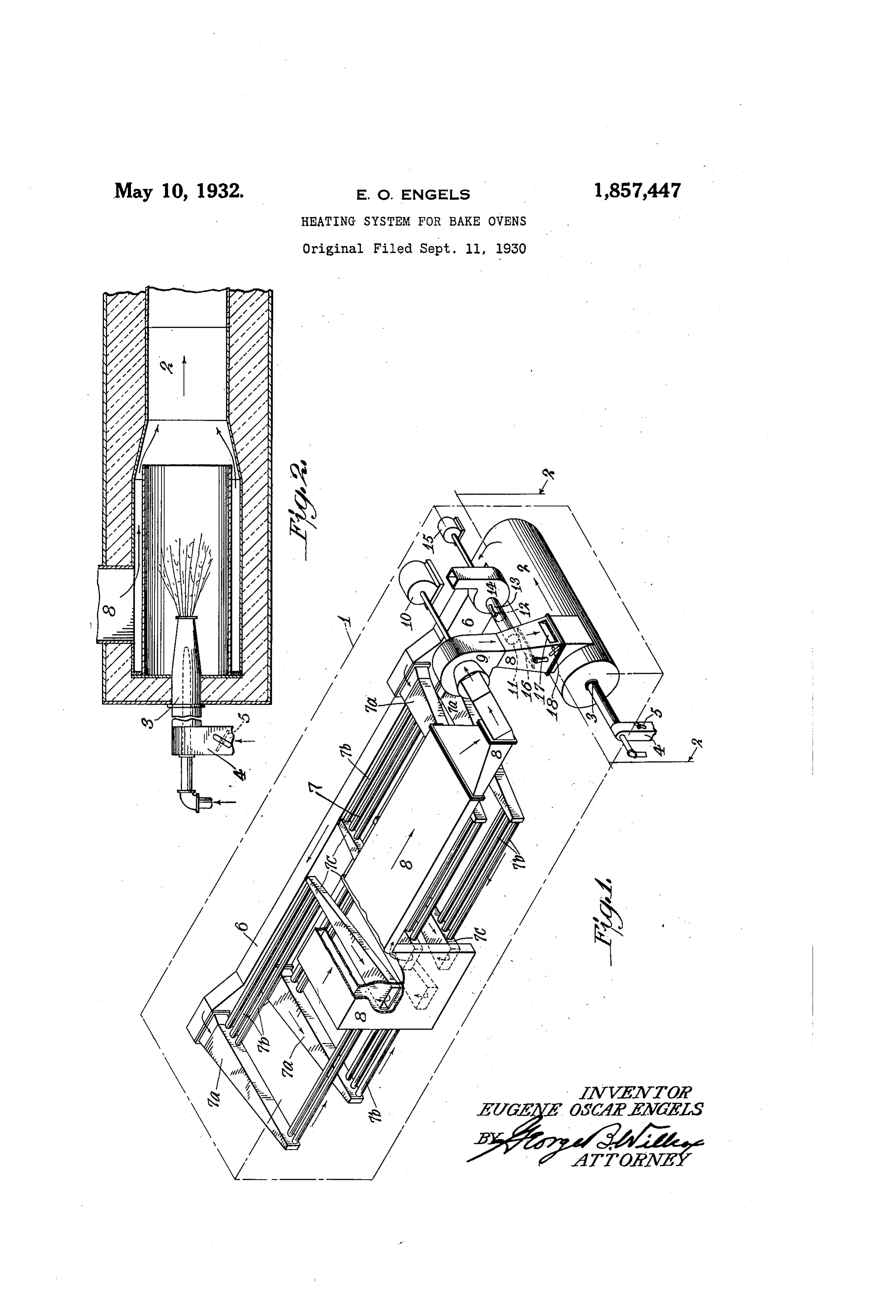
Application filed September 11, 1930, Serial No. 481,112. Renewed August 20, 1931. This invention relates to bake ovens heated support combustion drawn into the furnace by circulating hot gases from a furnace through a restricted duct or opening. through radiating flues in the baking cham ? preferred embodiment of my invention ber and back through the furnace, venting is illustrated in the accompanying drawings, off enough of the gases of combustion to bal of which : 55 ance the intake of air necessary for combus Fig. 1 is an isometric view, showing dia tion. grammatically a complete operating assem The object of my invention is to provide a bly as employed to heat a single-lap travel bake-oven heating system of this type where ling tray oven. ? o in a sub-atmospheric pressure of the hot gases tionFig. 2 is a fragmentary longitudinal sec 60 of the fuelburnerandthe furnace—taken `is established and maintained within the radiating flues or flue radiator, and the fur alongline 3—3 of Fig. 1.
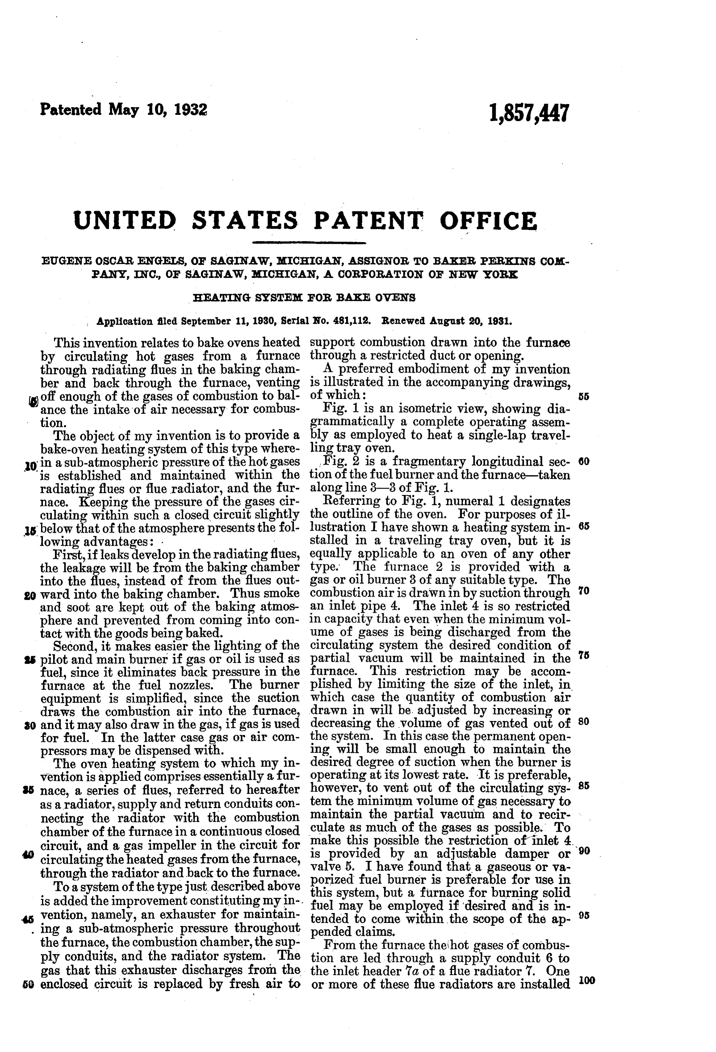
nace. Keeping the pressure of the gases cir Referring to Fig. 1, numeral 1 designates culating within such a closed circuit slightly the outline of the oven. E'or purposes of il 65 us lowing below that of the atmosphere presents the", fol lustration I have shown a heating system in advantages: . stalled in a traveling tray oven, but it is First,ifleaks developin the radiatingfiues, equally applicable to an oven of any other the leakage will be from the baking chamber type. The furnace 2 is provided with a into the flues, instead of from the flues out gas or oil burner 3 of any suitable type. The go wardinto the baking chamber. Thussmoke combustion air is drawn in by suction through 70 and soot are kept out of the baking atmos an inlet pipe 4. The inlet 4 is so restricted phere and prevented from coming into con in capacity that even when the minimum vol tact with the goods being baked. ume of gases is being discharged from the Second, it makes easier the lighting of the circulating system the desired condition of 75 ?s pilot and main burner if gas or oil is used as partial v??uum will be maintained in the fuel, since it eliminates back pressure in the furnace. This restriction may be accom furnace at the fuel nozzles. The burner plished by limiting the size of the inlet, in. equipment is simplified, since the suction which case the quantity of combustion air draws the combustion air into the furnace, drawn in will be adjusted by increasing or ?? and it may also draw in the gas, ifgas is used decreasing the volume of gas vented out of 80 for fuel. In the latter case gas or air com the system. In this case the permanent open pressors may be dispensed with. ing will be small enough to maintain the The oven heating system to which my in desired degree of suction when the burner is vention is applied comprises essentially a fur operating at its lowest rate. It is preferable, 85 nace, a series of flues, referred to hereafter however, tovent out of the circulating sys as a radiator, supply and return conduits con tem the minimum?olume ofgas necessary to maintain the partial v??uum and to recir necting the radiator with the combustion culate as much of the gases as possible. To chamber of the furnacein a continuous closed circuit, and a gas impeller in the circuit for make this possible the restriction of inlet 4. 90 is provided by an adjustable damper or circulatingthe heated gases from the furnace, valve through the radiator andback to the furnace. porized5. fuel
I have found that a gaseous or v?
burner is preferable for use in
Toasystem of thetypejust described above this system, but a furnace for burning solid is addedthe improvement constituting my in fuel may be employed vention, namely, an exhauster for maintain tended to come within if the desired and is in 95 scope of the ap ing a sub-atmospheric pressure throughout pended claims.
the furnace, the combustion chamber, the sup From the furnace thehot gases of combus ply conduits, and the radiator system. The tion are led through a supply conduit 6 to gas that this exhauster discharges from the the inlet header 7a of a flue radiator 7. One 5o enclosed circuit is replaced by fresh air to or more of these flue radiators are installed
Page 3
Drawing sheet — no readable text.
Page 4
Having thus described my invention, what I claim and desire to secure by Letters Pat
1. In combination a bake oven having a 5 flue radiator therein, a furnace having a gas air burner, conduits connecting the combus tion chamber of the furnace with the radia tor in continuous closed circuit, a gas impel ler located within said closed circuit and . 10 power-driven, an exhaust fan operative inde pendently of said impeller and having its in take side in communication with said circuit between the outlet ofsaid radiator and thein let to said furnace, for maintaining pressure 18 less than atmospheric within the radiator and within the furnace chamber, said exhaust fan arranged to discharge outside of said circuit.
2. In combination a bake oven having a 20 radiator therein, a furnace, conduits connect ing said radiator with the combustion cham ber of said furnace in continuous closed cir ?uit, agas impeller located within said closed circuit, an exhauster in communication with 25 said circuit and a restricted fresh air inlet to said furnace of size so proportioned to the ?? pacity of said exhauster that the pressure within said radiatorandfurnaceismaintained at less than that of the atmosphere when said 80 furnace and exhauster are in operation. 3. In combination, a bake oven having a flue radiator therein, a furnace having a fuel air burner, a restricted combustion air inlet to said furnace, conduits connecting the com 35 bustion chamber of said furnace with the ra diator in continuous closed circuit, a power driven gas impeller within said closed circuit to maintain continuous circulation ofgases of combust?on through the circuit, and a valved 40) gas vent to the atmosphere from said circuit located between the pressureside of said im peller and said furnace, adapted to vent off a volume of gas larger than the volume of air enteringthe furnace to maintain a sub-atmos 45 pheric pressure in that part of the circuit which includes said furnace and said ra diator.
4. In combination, a bake oven having a
flue radiator therein, a furnace, a valve controlled air inlet to said furnace, conduits connecting said furnace with said radiator in continuous closed circuit, a gasimpeller with in said closed circuit to maintain continuous circulation of the gases of combustion through said circuit, and means for discharg ing gases from said circuit to the atmosphere in such quantity as to maintain a sub-at mospheric pressure in that portion of said circnit including said furnace and said flue 60 radiator.
In testimony whereof, I affix my signature. EUGENE os?AR ENGELs.
Provenance
- Collection
- Cited prior art
- Original PDF
- patentimages.storage.googleapis.com →
- Filed
- 1930-09-11
- Pages
- 4
- Method
- pdftotext (the PDF's own text layer) + pdftoppm 300dpi page scans
- Source
- Google Patents bibliographic record
- Granted
- 1932-05-10
- Inventors
- Engels Eugene Oscar; Baker Perkins Inc
- Transcribed from
- patentimages.storage.googleapis.com →