patent · US4306858
Recuperative heating unit for industrial furnace
22 December 1981
Page 1 — bibliographic record
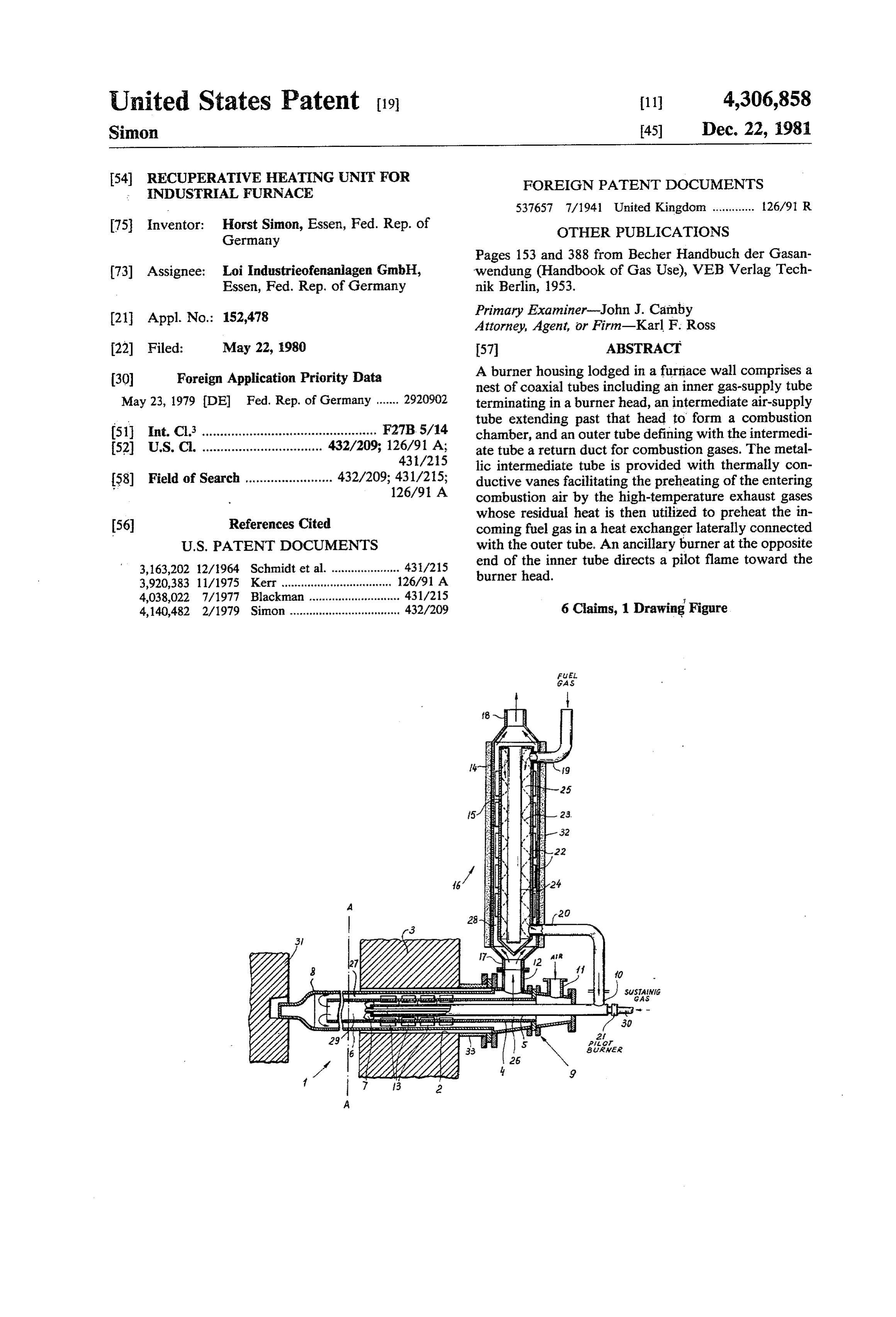
United States Patent (19) 11) 4,306,858 Simon 45 Dec. 22, 1981 54 RECUPERATIVE HEATING UNIT FOR FOREIGN PATENT DOCUMENTS
INDUSTRIAL FURNACE
75 Inventor: Horst Simon, Essen, Fed. Rep. of OTHER PUBLICATIONS Germany
Pages 153 and 388 from Becher Handbuch der Gasan 73) Assignee: Loi Industrieofenanlagen GmbH, wendung (Handbook of Gas Use), VEB Verlag Tech Essen, Fed. Rep. of Germany nik Berlin, 1953.
(21 Appl. No.: 152,478 Primary Examiner-John J. Camby Attorney, Agent, or Firm-Karl F. Ross 22 Filed: May 22, 1980 57 ABSTRACT 30 Foreign Application Priority Data A burner housing lodged in a furnace wall comprises a nest of coaxial tubes including an inner gas-supply tube
May 23, 1979 IDE Fed. Rep. of Germany ....... 29.20902 terminating in a burner head, an intermediate air-supply tube extending past that head to form a combustion 51 Int. Cl. ................................................ F27B5/14 chamber, and an outer tube defining with the intermedi 52 U.S. Cl. ................................. 432/209; 126/91 A; ate tube a return duct for combustion gases. The metal 431/25 lic intermediate tube is provided with thermally con 58) Field of Search ........................ 432/209; 431/215; ductive vanes facilitating the preheating of the entering 126/91 A combustion air by the high-temperature exhaust gases
whose residual heat is then utilized to preheat the in coming fuel gas in a heat exchanger laterally connected
3,163,202 12/1964 Schmidt et al. ..................... 431/215 end of the inner tube directs a pilot flame toward the 3,920,383 11/1975 Kerr ............... ... 126/91 A burner head.
4,038,022 7/1977 Blackman ............................ 431/215 4,140,482 2/1979 Simon .................................. 432/209 6 Claims, 1 Drawing Figure
Page 2
Drawing sheet — no readable text.
Page 3
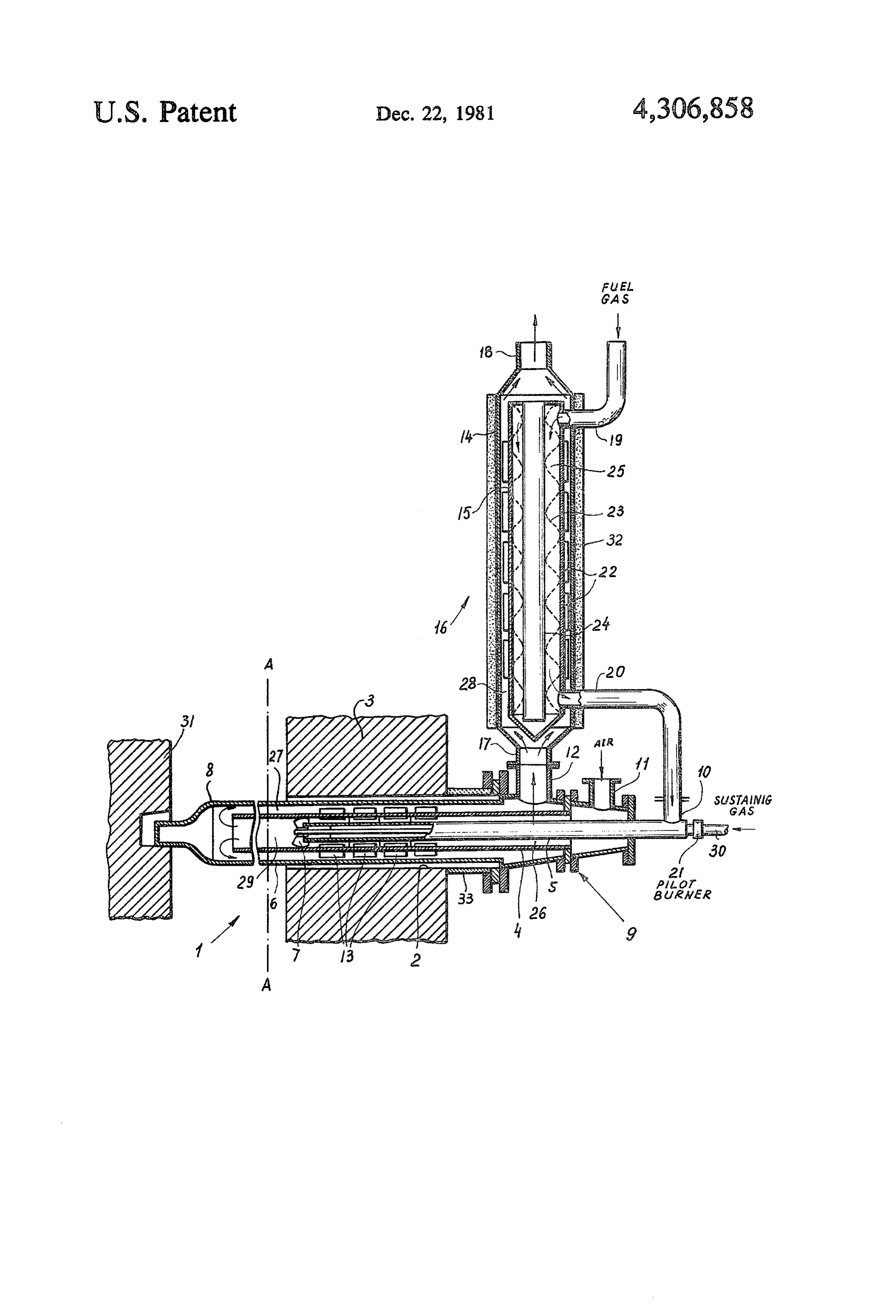
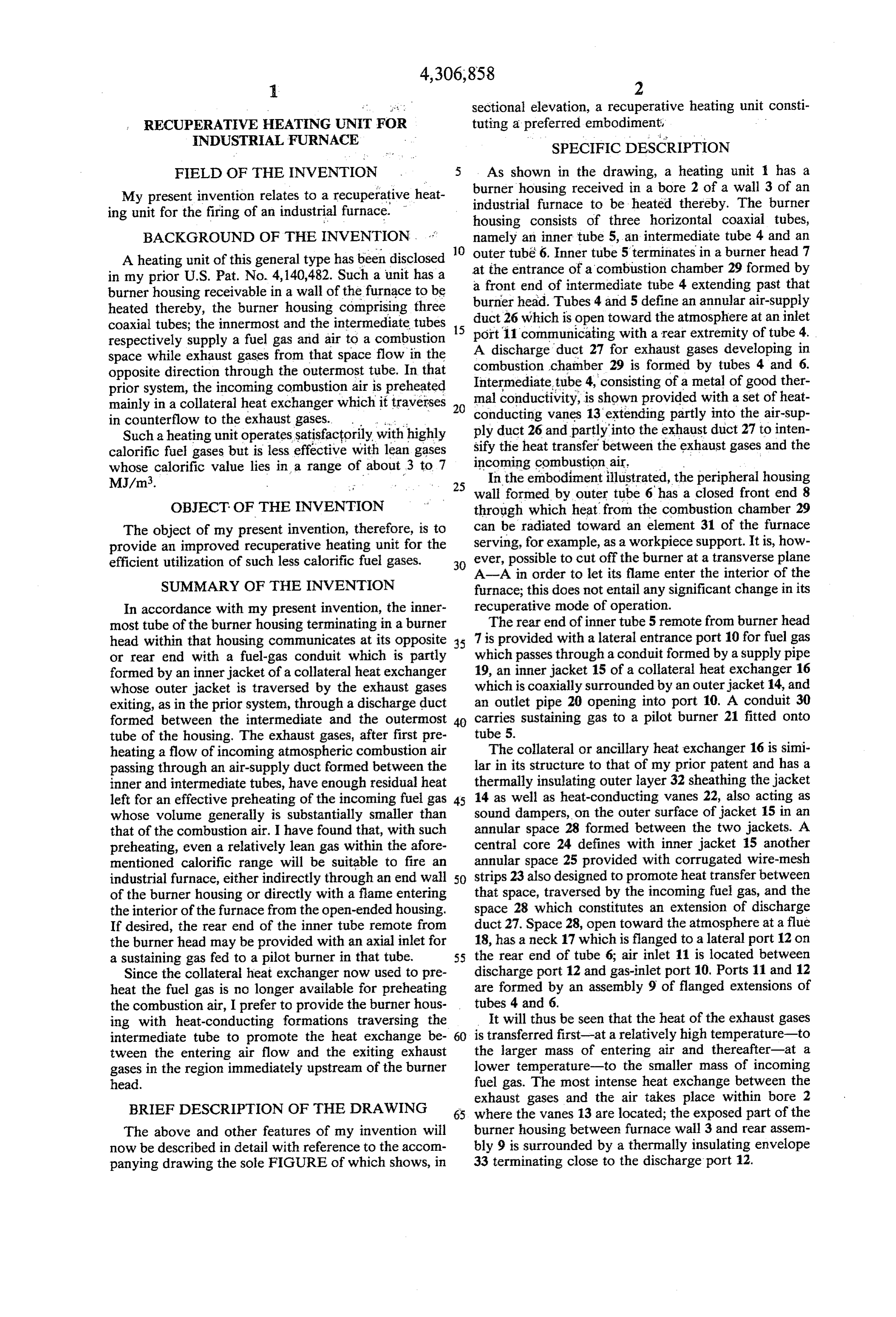
sectional elevation, a recuperative heating unit consti , RECUPERATEWE HEATING UNIT FOR tuting a preferred embodiment, INDUSTRIAL FURNACE SPECIFIC DESCRIPTION
FIELD OF THE INVENTION 5 As shown in the drawing, a heating unit has a My present invention relates to a recuperative heat burner housing received in a bore 2 of a wall 3 of an ing unit for the firing of an industrial furnace. " industrial furnace to be heated thereby. The burner housing consists of three horizontal coaxial tubes,
BACKGROUND OF THE INVENTION namely an inner tube 5, an intermediate tube 4 and an outer tube 6. Inner tube 5terminates in a burner head 7
A heating unit of this general type has been disclosed 10 at the entrance of a combustion chamber 29 formed by in my prior U.S. Pat. No. 4,140,482. Such a unit has a a front end of intermediate tube 4 extending past that burner housing receivable in a wall of the furnace to be burner head. Tubes 4 and 5 define an annular air-supply heated thereby, the burner housing comprising three duct 26 which is open toward the atmosphere at an inlet coaxial tubes; the innermost and the intermediate tubes 15 respectively supply a fuel gas and air to a combustion port A 11 communicating with a rear extremity of tube 4.
discharge duct 27 for exhaust gases developing in space while exhaust gases from that space flow in the combustion chamber 29 is formed by tubes 4 and 6. opposite direction through the outermost tube. In that Intermediate tube 4, consisting of a metal of good ther prior system, the incoming combustion air is preheated mal conductivity, is shown provided with a set of heat mainly in a collateral heat exchanger which it traverses 20 conducting in counterflow to the exhaust gases. vanes 13 extending partly into the air-sup Such aheating unit operates satisfactorily with highly ply duct 26 and partly into the exhaust duct 27 to inten calorific fuel gases but is less effective with lean gases sify the heat transfer between the exhaust gases and the whose calorific value lies in a range of about 3 to 7 incoming combustion air.
In the embodiment illustrated, the peripheral housing
wall formed by outer tube 6 has a closed front end 8
OBJECT OF THE INVENTION through which heat from the combustion chamber 29 The object of my present invention, therefore, is to can be radiated toward an element 31 of the furnace provide an improved recuperative heating unit for the serving, for example, as a workpiece support. It is, how efficient utilization of such less calorific fuel gases. 30 ever, possible to cut off the burner at a transverse plane A-A in order to let its flame enter the interior of the
SUMMARY OF THE INVENTION furnace; this does not entail any significant change in its In accordance with my present invention, the inner recuperative mode of operation.
most tube of the burner housing terminating in a burner The rear end of inner tube 5 remote from burner head head within that housing communicates at its opposite 35 7 is provided with a lateral entrance port 10 for fuel gas or rear end with a fuel-gas conduit which is partly which passes through a conduit formed by a supply pipe formed by an inner jacket of a collateral heat exchanger 19, an inner jacket 15 of a collateral heat exchanger 16 whose outer jacket is traversed by the exhaust gases which is coaxially surrounded by an outer jacket 14, and exiting, as in the prior system, through a discharge duct an outlet pipe 20 opening into port 10. A conduit 30 formed between the intermediate and the outermost 40 carries sustaining gas to a pilot burner 21 fitted onto tube of the housing. The exhaust gases, after first pre tube 5.
heating a flow of incoming atmospheric combustion air The collateral or ancillary heat exchanger 16 is simi passing through an air-supply duct formed between the lar in its structure to that of my prior patent and has a inner and intermediate tubes, have enough residual heat thermally insulating outer layer 32 sheathing the jacket left for an effective preheating of the incoming fuel gas 45 14 as well as heat-conducting vanes 22, also acting as whose volume generally is substantially smaller than sound dampers, on the outer surface of jacket 15 in an that of the combustion air. I have found that, with such annular space 28 formed between the two jackets. A preheating, even a relatively lean gas within the afore central core 24 defines with inner jacket 15 another mentioned calorific range will be suitable to fire an annular space 25 provided with corrugated wire-mesh industrial furnace, either indirectly through an end wall 50 strips 23 also designed to promote heat transfer between of the burner housing or directly with a fame entering that space, traversed by the incoming fuel gas, and the the interior of the furnace from the open-ended housing. space 28 which constitutes an extension of discharge If desired, the rear end of the inner tube remote from duct 27. Space 28, open toward the atmosphere at a flue the burner head may be provided with an axial inlet for 18, has a neck 17 which is flanged to a lateral port 12 on a sustaining gas fed to a pilot burner in that tube. 55 the rear end of tube 6; air inlet 11 is located between Since the collateral heat exchanger now used to pre discharge port 12 and gas-inlet port 10, Ports 11 and 12 heat the fuel gas is no longer available for preheating are formed by an assembly 9 of flanged extensions of the combustion air, I prefer to provide the burner hous tubes 4 and 6.
ing with heat-conducting formations traversing the It will thus be seen that the heat of the exhaust gases intermediate tube to promote the heat exchange be 60 is transferred first-at a relatively high temperature-to tween the entering air flow and the exiting exhaust the larger mass of entering air and thereafter-at a gases in the region immediately upstream of the burner lower temperature-to the smaller mass of incoming head. fuel gas. The most intense heat exchange between the
BRIEF DESCRIPTION OF THE DRAWING
exhaust gases and the air takes place within bore 2 65 where the vanes 13 are located; the exposed part of the
The above and other features of my invention will burner housing between furnace wall 3 and rear assen now be described in detail with reference to the accom bly 9 is surrounded by a thermally insulating envelope panying drawing the sole FIGURE of which shows, in 33 terminating close to the discharge port 12.
Page 4
Only a small amount of sustaining gas will be needed diate tube by high-temperature exhaust gases leav even with lean fuel gas to maintain combustion in ing the vicinity of said burner head, said exhaust burner chamber 29. With richer fuels the influx of sus gases thereupon entering said extension to preheat taining gas may be discontinued. incoming fuel gas in said conduit through said inner I claim: 5 jacket before escaping into the atmosphere. 1. A recuperative heating unit for the firing of an 2. A heating unit as defined in claim 1 wherein said industrial furnace, comprising: intermediate tube is provided with heat-conducting a burner assembly receivable in a furnace wall, said formations extending partly into said air-supply duct burner assembly including an inner tube terminat and partly into said discharge duct. ing in a burner head, an intermediate tube coaxially 10 3. A heating unit as defined in claim 1 or 2 wherein surrounding said inner tube and forming therewith said extension communicates with said discharge duct an air-supply duct, and an outer tube constituting a through a lateral port on said outer tube, said jackets peripheral housing wall, said outer tube coaxially having an axis substantially perpendicular to the axis of surrounding said intermediate tube and forming said tubes.
therewith a discharge duct for exhaust gases evolv 15 4. A heating unit as defined in claim 3 wherein said ing in the vicinity of said burner head; fuel-gas conduits has an outlet opening laterally into a recuperative heat exchanger comprising an outer said remote end of said inner tube, said air inlet being jacket and an inner jacket coaxial with each other disposed on an extension of said intermediate tube be and spaced from said burner assembly, said inner tween said lateral port and said outlet. jacket forming part of said fuel-gas conduit, said 20 5. A heating unit as defined in claim 4 wherein said outer jacket defining with said inner jacket an ex inner tube is provided at said remote end with a pilot tension of said discharge duct open toward the burner having an inlet for a sustaining gas. atmosphere; and 6. A heating unit as defined in claim 1 or 2 wherein an inlet for atmospheric combustion air communicat said intermediate tube extends within said outer tube ing with said intermediate tube at an extremity 25 beyond said burner head to form an open-ended com thereof remote from said burner head whereby said bustion chamber.
combustion air is preheated through said interme : xk :k k :k
Provenance
- Collection
- Cited prior art
- Original PDF
- patentimages.storage.googleapis.com →
- Filed
- 1980-05-22
- Pages
- 4
- Method
- pdftotext (the PDF's own text layer) + pdftoppm 300dpi page scans
- Source
- Google Patents bibliographic record
- Granted
- 1981-12-22
- Inventors
- Horst Simon; Loi Industrieofenanlagen GmbH
- Transcribed from
- patentimages.storage.googleapis.com →