patent · US4840560
Heating stock in a heating chamber
20 June 1989
Page 1 — bibliographic record
United States Patent (19) (11 Patent Number: 4,840,560 Waddington 45 Date of Patent: Jun. 20, 1989 (54) HEATING STOCK IN A HEATING 4,303,388 12/1981 Elhaus ................................. 432/236 CHAMBER 4,410,308 10/1983 McElroy. ... 432/59 4,529,379 7/1985 DiCastri........ ... 432/59 75) Inventor: John D. Waddington, Solihull, United 4,620,840 11/1986 Hilge et al. ......................... 432/121 Kingdom
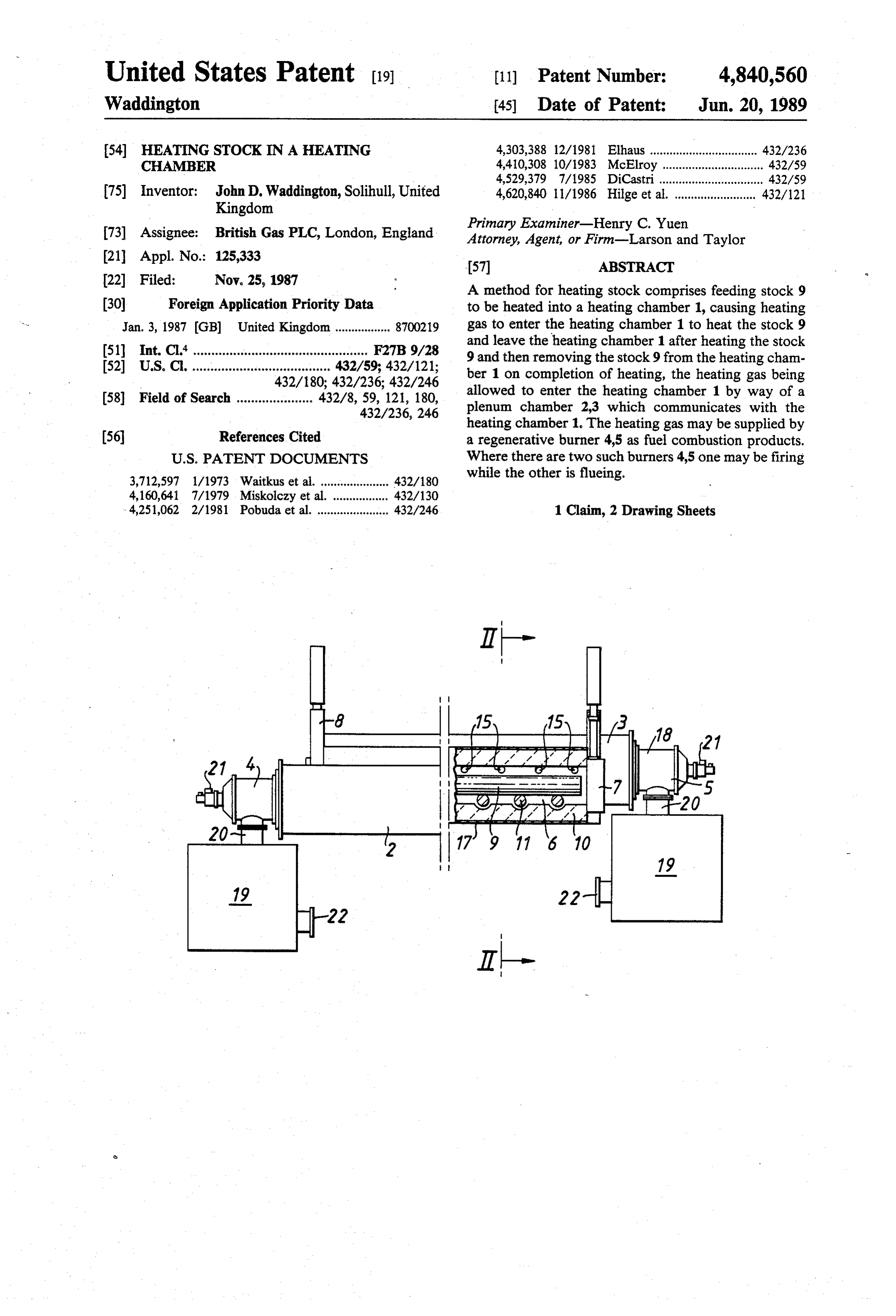
Primary Examiner-Henry C. Yuen 73) Assignee: British Gas PLC, London, England Attorney, Agent, or Firm-Larson and Taylor 21 Appl. No.: 125,333 57 ABSTRACT 22 Filed: Nov. 25, 1987 A method for heating stock comprises feeding stock 9 (30) Foreign Application Priority Data to be heated into a heating chamber 1, causing heating Jan. 3, 1987 GB) United Kingdom ................. 8700219 gas to enter the heating chamber 1 to heat the stock 9 51) Int. Cl. .............. to soooo to so or e o ose F27B 9/28 and leave the heating chamber 1 after heating the stock 52 U.S. C. ..... ... 432/59; 432/121; 9 and then removing the stock 9 from the heating cham 432/180; 432/236; 432/246 ber 1 on completion of heating, the heating gas being (58) Field of Search .................... 432/8, 59, 121, 180, allowed to enter the heating chamber 1 by way of a 432/236, 246 plenum chamber 2,3 which communicates with the heating chamber 1. The heating gas may be supplied by (56) References Cited a regenerative burner 4,5 as fuel combustion products.
3,712,597 1/1973 Waitkus et al. ..................... 432/180 while the other is flueing.
4,251,062 2/1981 Pobuda et al. ...................... 432/246 1 Claim, 2 Drawing Sheets
Page 2
Drawing sheet — no readable text.
Page 3
Drawing sheet — no readable text.
Page 4
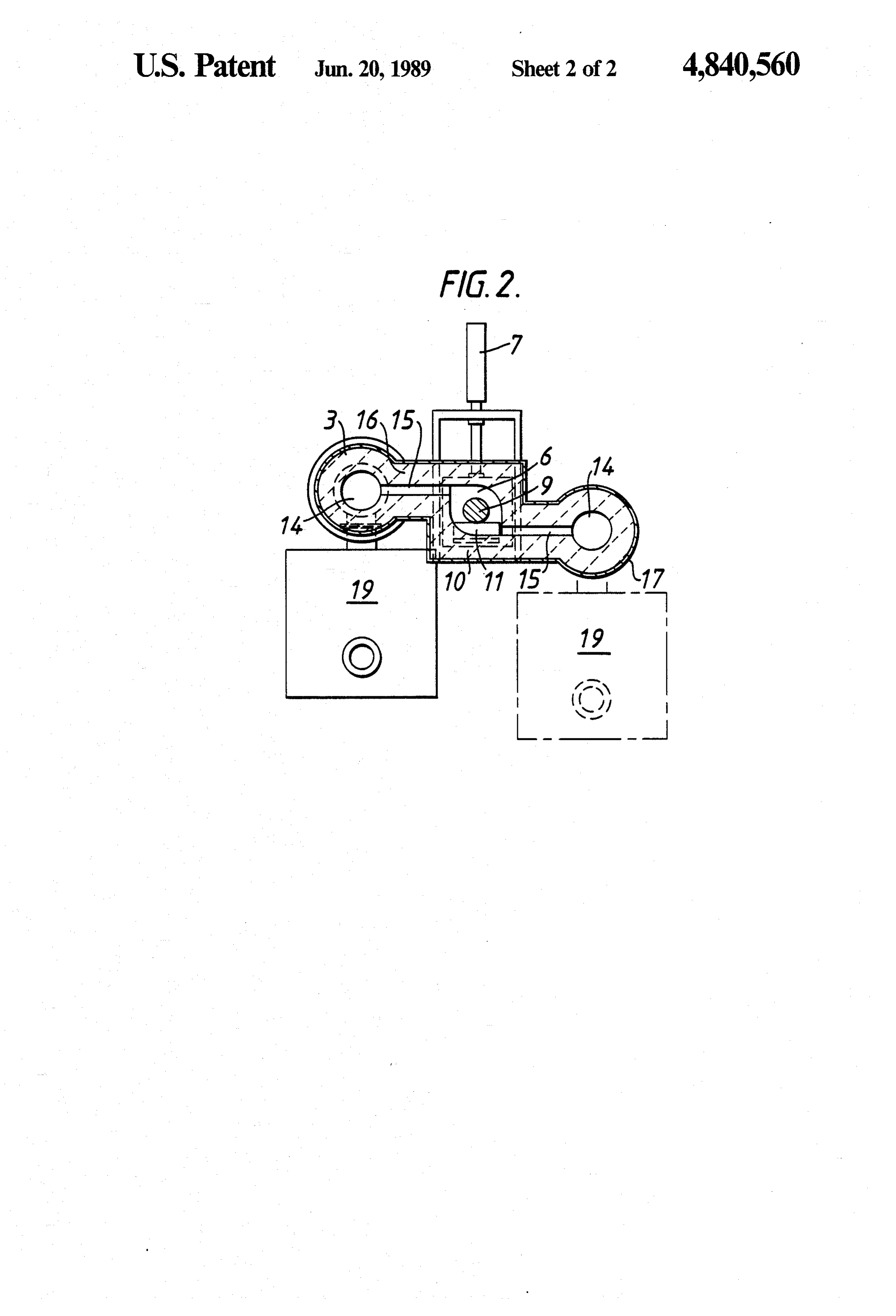
Along opposite sides of the heating chamber and of
HEATING STOCK N A HEATING CHAMBER the same length, are the plenum chambers 2, 3, each of which forms a generally cylindrical bore 14 extending
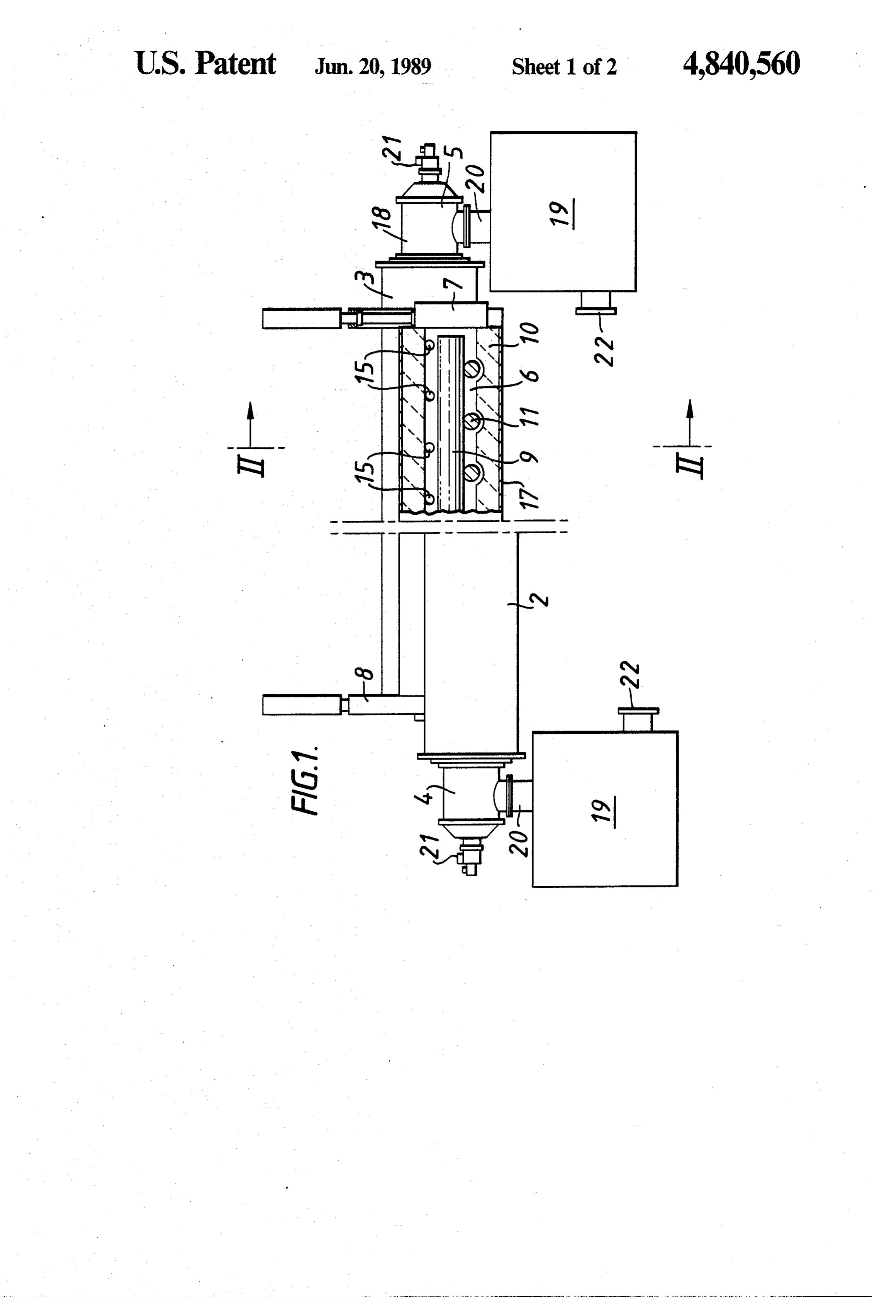
The present invention relates to the heating of stock parallel to the adjoining side of the furnace and each of in a heating chamber to which a heating gas is supplied 5 which communicate with the heating chamber 1 by way to heat the stock. According to one aspect of the inven of several longitudinally spaced ports 15 along the tion, a method is provided for heating stock comprising length of the heating chamber 1. The plenum chamber feeding stock to be heated into a heating chamber, caus 2 is displaced slightly writically below the plenum cham ing heating gas to enter the heating chamber to heat the 10 ber 3 and the plenum chambers 2, 3 and the heating stock and leave the heating chamber after heating the chamber 1 are refractory lined 16 and contained in an stock and then removing the stock from the heating outermost casing 17.
chamber on completion of heating, the heating gas Each plenum chambers 2, 3 is either closed at one end being allowed to enter the heating chamber by way of a (not shown) and is provided at the other end with a regenerative type burner 4, 5 each of which is arranged plenum chamber which communicates with the heating 15 adjacent opposite ends of the heating chamber 1 or chamber.
According to another aspect of the present invention provided with regenerative type burners on both ends. The regenerative burners 4, 5 are of conventional apparatus is provided for heating stock comprising a construction and comprise a fuel-fired burner 18 and heating chamber for receiving the stock for heating associated regenerator with a heating gas, a plenum chamber which communi 20 In a firing mode eachchamber 19. cates with the heating chamber, a fuel-fired burner for plenum chamber with heating gas inburner regenerative supplies its supplying heating gas to the plenum chamber for distri combustion products. In a flueing mode each of the form fuel burner bution to the heating chamber, there being means for receives waste gas from its plenum chamber for subse exhausting waste gas from the heating chamber.
According to a further aspect of the present invention 25 quent
The discharge.
regenerator chamber 19 communicates with the apparatus is provided for heating stock comprising a heating chamber for receiving the stock for heating burner part 18 by way of a duct 20. with a heating gas, a first plenum chamber adjoining a the burner firing
During the regenerator chamber 19 supplies first side of the heating chamber and communicating 20 for combustion with part 18 preheated airby way of the duct with fuel, eg. natural gas supplied to with the chamber through the first side, a second ple 30 the burner part 18 by a fuel pipe 21. The air for preheat num chamber adjoining a second side of the heating ing in the regenerator 19 is supplied to the regenerator chamber and communicating with the chamber through 19 by a pipe 22.
the second side, a first regenerative type burner commu During flueing waste gas entering the burner part 18 nicating with the first plenum chamber and a second is discharged to the regenerator chamber 19 by way of regenerative type burner communicating with the sec 35 the duct 20 and is discharged from the regenerator 19 ond plenum chamber, each burner being adapted on its by way of the pipe 22.
firing cycle to supply heating gas to its plenum chamber In use, the stock heating can either be "batch' or for subsequent distribution to the heating chamber for "continuous' depending upon the process require heating the stock and on its flueing cycle to receive ments.
from its plenum chamber waste gas discharged from the In the "batch' mode, which would be used for heat heating chamber, the arrangement being that, in use, ing single long metal billets, one burner would fire into while one burner is firing the other is flueing. its plenum chamber for the complete heating cycle of An embodiment of the invention will now be particu the one billet within the heating chamber. The other larly described with reference to the drawings in which: plenum chamber would act as a manifold for receiving FIG. 1 is a side elevation partly in section of an appa 45 the waste combustion products from the heating cham ratus for heating stock, and ber with the other burner operating in a flueing mode. FIG. 2 is a view along the lines II-II of FIG. 1. On completion of the heating cycle the firing burner Referring to the drawings, the apparatus comprises a could be shut down whilst the heated billet was re heating chamber 1, two plenum chambers 2, 3, each moved from the heating chamber which would be re communicating with the heating chamber 1 and a pair 50 charged with cold stock. On restart the burner which of regenerative type burners 4, 5, one burner communi had previously been flueing would now fire while that cating with a matching plenum chamber. burner which had previously been firing would now The heating chamber 1 comprises an elongate gener serve as a flue. This cycle would be repeated. ally rectangular or circular cross section furnace which In "continuous' mode which could be used for heat is designed to reheat metal stock such as large section 55 ing short billets where the heating chamber would con round or square billets. tain a large number of individual billets, each burner The chamber 1 forms an elongate enclosure 6 to re firing period could be of predetermined duration, possi ceive the stock to be heated such as a long billet (eg. an bly to coincide with the discharge interval of the stock, aluminum log) or a multiplicity of billets (such as those or alternatively, the firing period could be controlled by used in forging or extrusion). The enclosure 6 is closed the temperature of the waste gases leaving the regenera at either end by doors 7 and 8 which are raisable verti tor of the burner which is flueing. cally to permit entry and discharge of a billet (such as The provision of the plenum chambers along the sides that shown by reference 9). The billet 9 enters via door of the heating chamber enables the heating gas to be 7 and leaves via door 8. distributed to the heating chamber in a far more uniform The floor 10 of the enclosure 6 is provided with a 65 manner than would be the case if as conventional the means of stock conveying such as driven rolls 11 along burners were to be firing directly into the heating cham which the billet 9 can be moved into and out of the ber. Furthermore, the provision of plenum chambers enclosure 6. enables the number of burners per particular heating
Page 5
chamber to be reduced together with the number and chamber, a fist regenerative type burner communicat complexity of controls. ing with the opening at the end of said first plenum, a I claim: second regenerative type burner communicating with 1. Apparatus for heating stock comprising a heating the opening at the end of said second plenum, each chamber for receiving stock for heating with a heating 5 burner being adapted on its firing cycle to supply heat gas, a first elongated plenum chamber extending along ing gas to its plenum chamber in a direction parallel to one side of said heating chamber and having an opening the side of the heating chamber for subsequent distribu at one end thereof, a second elongated plenum chamber tion to the heating chamber for heating the stock and on extending adjacent the opposite side of said heating its flueing cycle to receive from its plenum chamber chamber and having an opening at one end thereof, a 10 waste gas discharged from the heating chamber, the first plurality of ports communicating said first plenum arrangement being that, in use, while one burner is with said heating chamber, a second plurality of ports firing the other is flueing.
communicating said second plenum with said heating

Provenance
- Collection
- Cited prior art
- Original PDF
- patentimages.storage.googleapis.com →
- Filed
- 1987-11-25
- Pages
- 5
- Method
- pdftotext (the PDF's own text layer) + pdftoppm 300dpi page scans
- Source
- Google Patents bibliographic record
- Granted
- 1989-06-20
- Inventors
- John D. Waddington; British Gas PLC
- Transcribed from
- patentimages.storage.googleapis.com →