patent · US4730599
Radiant tube heating system
15 March 1988
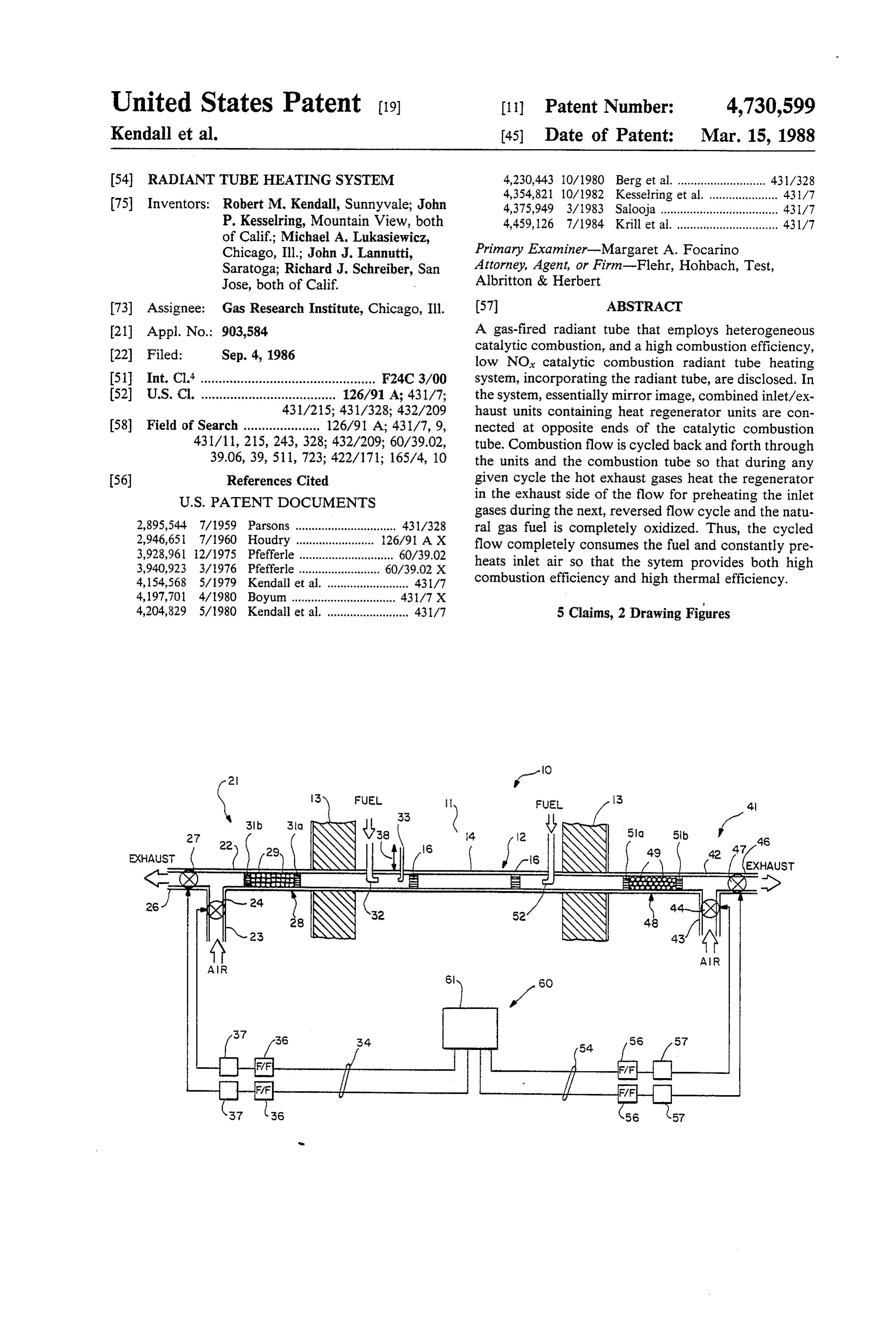
Page 1 — bibliographic record
United States Patent (19) 11 Patent Number: 4,730,599 Kendall et al. 45) Date of Patent: Mar. 15, 1988 54 RADIANT TUBE HEATING SYSTEM 4,230,443 10/1980 Berg et al. ........................... 431/328
(75) Inventors: Robert M. Kendall, Sunnyvale; John 4,375,949 3/1983 Salooja ............. P. Kesselring, Mountain View, both 4,459,126 7/1984 Krill et al................................ 431/7 of Calif.; Michael A. Lukasiewicz,
Chicago, Ill.; John J. Lannutti, Primary Examiner-Margaret A. Focarino
Saratoga; Richard J. Schreiber, San Attorney, Agent, or Firm-Flehr, Hohbach, Test,
Jose, both of Calif. Albritton & Herbert (73) Assignee: Gas Research Institute, Chicago, Ill. 57 ABSTRACT 21 Appl. No.: 903,584 A gas-fired radiant tube that employs heterogeneous 22 Filed: Sep. 4, 1986 catalytic combustion, and a high combustion efficiency, low NO catalytic combustion radiant tube heating 51 Int. Cl." ................................................ F24C3/00 system, incorporating the radiant tube, are disclosed. In 52 U.S. C. ..................................... 126/91 A; 431/7; the system, essentially mirror image, combined inlet/ex 431/215; 431/328; 432/209 haust units containing heat regenerator units are con (58) Field of Search ..................... 126/91 A; 431/7, 9, nected at opposite ends of the catalytic combustion 431/11, 215, 243, 328; 432/209; 60/39.02, tube. Combustion flow is cycled back and forth through 39.06, 39, 51 1,723; 422/171; 165/4, 10 the units and the combustion tube so that during any 56) References Cited given cycle the hot exhaust gases heat the regenerator
gases during the next, reversed flow cycle and the natu 2,895,544 7/1959 Parsons ............................... 431/328 ral gas fuel is completely oxidized. Thus, the cycled 2,946,651 7/1960 Houdry ........................ 126/91 AX flow completely consumes the fuel and constantly pre 3,928,961 12/1975 Pfefferle ............................. 60/39.02 heats inlet air so that the sytem provides both high
4,154,568 5/1979 Kendall et al. ......................... 431/7 combustion efficiency and high thermal efficiency.
4,204,829 5/1980 Kendall et al. ......................... 431/7 5 Claims, 2 Drawing Figures
Page 2
Drawing sheet — no readable text.
Page 3
Drawing sheet — no readable text.
Page 4
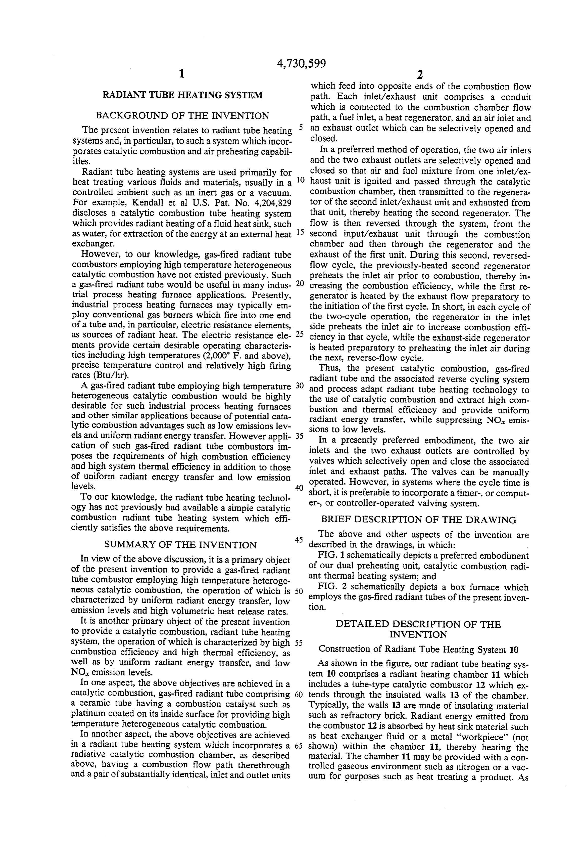
which feed into opposite ends of the combustion flow
RADIANT TUBE HEATING SYSTEM path. Each inlet/exhaust unit comprises a conduit which is connected to the combustion chamber flow
BACKGROUND OF THE INVENTION path, a fuel inlet, a heat regenerator, and an air inlet and The present invention relates to radiant tube heating an exhaust outlet which can be selectively opened and systems and, in particular, to such a system which incor closed.
porates catalytic combustion and air preheating capabil In a preferred method of operation, the two air inlets ities. and the two exhaust outlets are selectively opened and Radiant tube heating systems are used primarily for closed so that air and fuel mixture from one inlet/ex heat treating various fluids and materials, usually in a 10 haust unit is ignited and passed through the catalytic controlled ambient such as an inert gas or a vacuum. combustion chamber, then transmitted to the regenera For example, Kendall et al U.S. Pat. No. 4,204,829 tor of the second inlet/exhaust unit and exhausted from discloses a catalytic combustion tube heating system that unit, thereby heating the second regenerator. The which provides radiant heating of a fluid heat sink, such 15 flow is then reversed through the system, from the as water, for extraction of the energy at an external heat second input/exhaust unit through the combustion exchanger. chamber and then through the regenerator and the However, to our knowledge, gas-fired radiant tube exhaust of the first unit. During this second, reversed combustors employing high temperature heterogeneous flow cycle, the previously-heated second regenerator catalytic combustion have not existed previously. Such preheats the inlet air prior to combustion, thereby in a gas-fired radiant tube would be useful in many indus 20 creasing the combustion efficiency, while the first re trial process heating furnace applications. Presently, generator is heated by the exhaust flow preparatory to industrial process heating furnaces may typically em the initiation of the first cycle. In short, in each cycle of ploy conventional gas burners which fire into one end the two-cycle operation, the regenerator in the inlet of a tube and, in particular, electric resistance elements, side preheats the inlet air to increase combustion effi as sources of radiant heat. The electric resistance ele 25 ciency in that cycle, while the exhaust-side regenerator ments provide certain desirable operating characteris is heated preparatory to preheating the inlet air during tics including high temperatures (2,000 F. and above), the next, reverse-flow cycle.
precise temperature control and relatively high firing Thus, the present catalytic combustion, gas-fired rates (Btu/hr). radiant tube and the associated reverse cycling system A gas-fired radiant tube employing high temperature 30 and process adapt radiant tube heating technology to heterogeneous catalytic combustion would be highly the use of catalytic desirable for such industrial process heating furnaces bustion and thermalcombustion efficiency and extract high com and provide uniform and other similar applications because of potential cata radiant energy transfer, while suppressing NOx emis lytic combustion advantages such as low emissions lev sions to low levels.
els and uniform radiant energy transfer. However appli 35
In a presently preferred embodiment, the two air cation of such gas-fired radiant tube combustors im poses the requirements of high combustion efficiency inlets valves and the two exhaust outlets are controlled by which selectively open and close the associated and high system thermal efficiency in addition to those inlet and of uniform radiant energy transfer and low emission operated. exhaust paths. The valves can be manually However, in systems where the cycle time is levels.
To our knowledge, the radiant tube heating technol short, er-, or it is preferable to incorporate a timer-, or comput controller-operated valving system.
ogy has not previously had available a simple catalytic combustion radiant tube heating system which effi BRIEF DESCRIPTION OF THE DRAWING ciently satisfies the above requirements.
45 The above and other aspects of the invention are
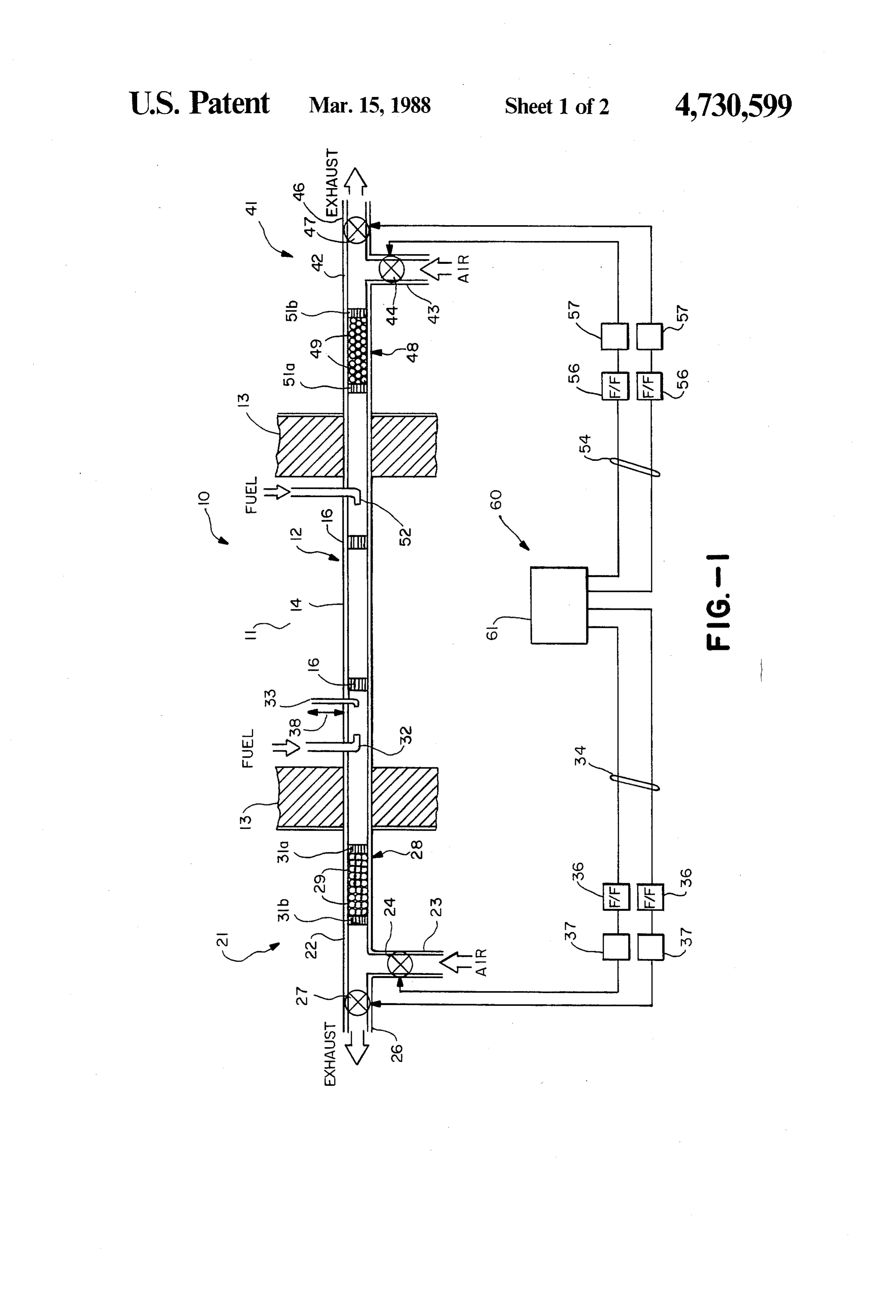
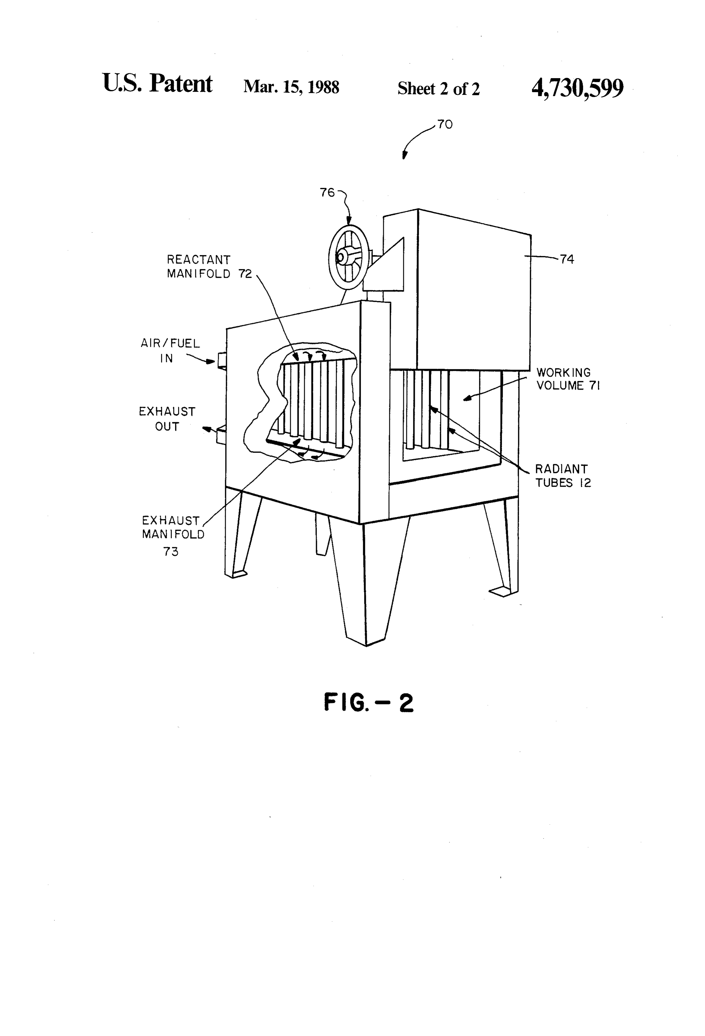
SUMMARY OF THE INVENTION described in the drawings, in which: In view of the above discussion, it is a primary object FIG. 1 schematically depicts a preferred embodiment of the present invention to provide a gas-fired radiant of our dual preheating unit, catalytic combustion radi tube combustor employing high temperature heteroge ant thermal heating system; and neous catalytic combustion, the operation of which is 50 employs FIG. 2 schematically depicts a box furnace which characterized by uniform radiant energy transfer, low tion. the gas-fired radiant tubes of the present inven emission levels and high volumetric heat release rates.
It is another primary object of the present invention DETAILED DESCRIPTION OF THE to provide a catalytic combustion, radiant tube heating INVENTION system, the operation of which is characterized by high 55 combustion efficiency and high thermal efficiency, as Construction of Radiant Tube Heating System 10 well as by uniform radiant energy transfer, and low As shown in the figure, our radiant tube heating sys NOx emission levels. tem 10 comprises a radiant heating chamber 11 which In one aspect, the above objectives are achieved in a includes a tube-type catalytic combustor 12 which ex catalytic combustion, gas-fired radiant tube comprising 60 tends through the insulated walls 13 of the chamber. a ceramic tube having a combustion catalyst such as Typically, the walls 13 are made of insulating material platinum coated on its inside surface for providing high such as refractory brick. Radiant energy emitted from temperature heterogeneous catalytic combustion. the combustor 12 is absorbed by heat sink material such In another aspect, the above objectives are achieved as heat exchanger fluid or a metal "workpiece' (not in a radiant tube heating system which incorporates a 65 shown) within the chamber 11, thereby heating the radiative catalytic combustion chamber, as described material. The chamber 11 may be provided with a con above, having a combustion flow path therethrough trolled gaseous environment such as nitrogen or a vac and a pair of substantially identical, inlet and outlet units uum for purposes such as heat treating a product. As
Page 5
shown, the tubular catalytic combustion chamber 12 achieved without heat recuperation and at this rela may comprise a ceramic tube 14 coated with a layer of tively low combustion efficiency.
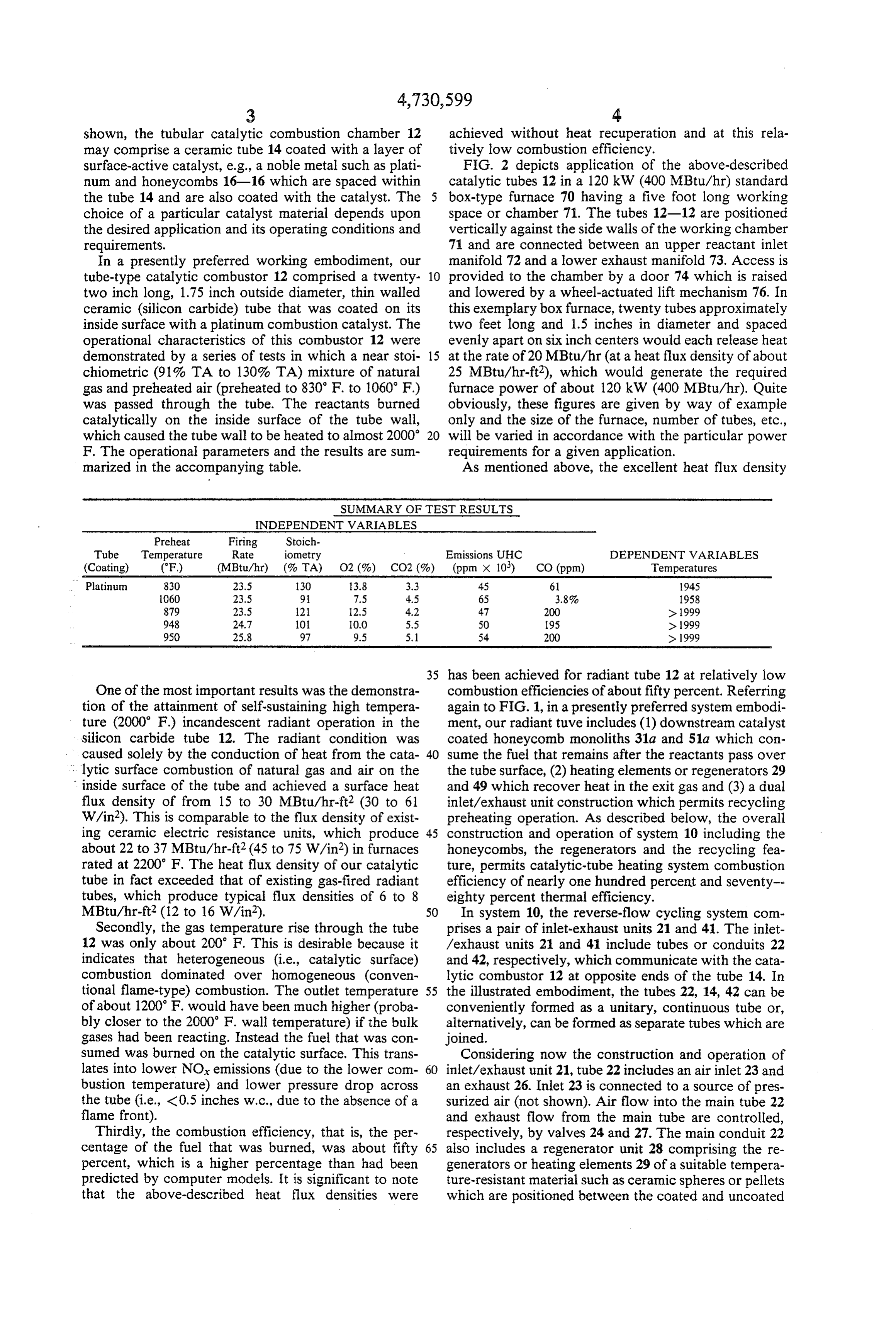
surface-active catalyst, e.g., a noble metal such as plati FIG. 2 depicts application of the above-described num and honeycombs 16-16 which are spaced within catalytic tubes 12 in a 120 kW (400 MBtu/hr) standard the tube 14 and are also coated with the catalyst. The box-type furnace 70 having a five foot long working choice of a particular catalyst material depends upon space or chamber 71. The tubes 12-12 are positioned the desired application and its operating conditions and vertically against the side walls of the working chamber requirements. 71 and are connected between an upper reactant inlet In a presently preferred working embodiment, our manifold 72 and a lower exhaust manifold 73. Access is tube-type catalytic combustor 12 comprised a twenty 10 provided to the chamber by a door 74 which is raised two inch long, 1.75 inch outside diameter, thin walled and lowered by a wheel-actuated lift mechanism 76. In ceramic (silicon carbide) tube that was coated on its this exemplary box furnace, twenty tubes approximately inside surface with a platinum combustion catalyst. The two feet long and 1.5 inches in diameter and spaced operational characteristics of this combustor 12 were evenly apart on six inch centers would each release heat demonstrated by a series of tests in which a near stoi 15 at the rate of 20 MBtu/hr (at a heat flux density of about chiometric (91%. TA to 130% TA) mixture of natural 25 MBtu/hr-ft2), which would generate the required gas and preheated air (preheated to 830 F. to 1060 F) furnace power of about 120 kW (400 MBtu/hr). Quite was passed through the tube. The reactants burned obviously, these figures are given by way of example catalytically on the inside surface of the tube wall, only and the size of the furnace, number of tubes, etc., which caused the tube wall to be heated to almost 2000 20 will be varied in accordance with the particular power F. The operational parameters and the results are sum requirements for a given application. marized in the accompanying table. As mentioned above, the excellent heat flux density
SUMMARY OF TEST RESULTS
INDEPENDENT WARIABLES
Preheat Firing Stoich
Tube Temperature Rate iometry Emissions UHC DEPENDENT WARIABLES (Coating) (F) (MBtu/hr) (%TA) O2 (%) CO2 (%) (ppm x 10) CO (ppm) Temperatures Platinum 830 23.5 130 3.8 3.3 45 61 1945 1060 23.5 9. 7.5 4.5 65 3.8% 1958 879 23.5 21 2.5 4.2 47 200 > 1999 948 24.7 101 O.O 5.5 50 95 > 1999 950 25.8 97 9.5 5.1 54 200 > 1999
35 has been achieved for radiant tube 12 at relatively low
One of the most important results was the demonstra combustion efficiencies of about fifty percent. Referring tion of the attainment of self-sustaining high tempera again to FIG. 1, in a presently preferred system embodi ture (2000 F) incandescent radiant operation in the ment, our radiant tuve includes (1) downstream catalyst silicon carbide tube 12. The radiant condition was coated honeycomb monoliths 31a and 51a which con caused solely by the conduction of heat from the cata 40 sume the fuel that remains after the reactants pass over lytic surface combustion of natural gas and air on the the tube surface, (2) heating elements or regenerators 29 inside surface of the tube and achieved a surface heat and 49 which recover heat in the exit gas and (3) a dual flux density of from 15 to 30 MBtu/hr-ft2 (30 to 61 inlet/exhaust unit construction which permits recycling W/in2). This is comparable to the flux density of exist preheating operation. As described below, the overall ing ceramic electric resistance units, which produce 45 construction and operation of system 10 including the about 22 to 37 MBtu/hr-ft2(45 to 75 W/in2) in furnaces honeycombs, the regenerators and the recycling fea rated at 2200 F. The heat flux density of our catalytic ture, permits catalytic-tube heating system combustion tube in fact exceeded that of existing gas-fired radiant efficiency of nearly one hundred percent and seventy tubes, which produce typical flux densities of 6 to 8 eighty percent thermal efficiency. MBtu/hr-ft2(12 to 16 W/in2). 50 In system 10, the reverse-flow cycling system com Secondly, the gas temperature rise through the tube prises a pair of inlet-exhaust units 21 and 4. The inlet 12 was only about 200 F. This is desirable because it /exhaust units 21 and 41 include tubes or conduits 22 indicates that heterogeneous (i.e., catalytic surface) and 42, respectively, which communicate with the cata combustion dominated over homogeneous (conven lytic combustor 12 at opposite ends of the tube 14. In tional flame-type) combustion. The outlet temperature 55 the illustrated embodiment, the tubes 22, 14, 42 can be of about 1200 F. would have been much higher (proba conveniently formed as a unitary, continuous tube or, bly closer to the 2000 F. wall temperature) if the bulk alternatively, can be formed as separate tubes which are gases had been reacting. Instead the fuel that was con joined.
Sumed was burned on the catalytic surface. This trans Considering now the construction and operation of lates into lower NOx emissions (due to the lower com 60 inlet/exhaust unit 21, tube 22 includes an air inlet 23 and bustion temperature) and lower pressure drop across an exhaust 26. Inlet 23 is connected to a source of pres the tube (i.e., <0.5 inches w.c., due to the absence of a surized air (not shown). Air flow into the main tube 22 flame front). and exhaust flow from the main tube are controlled, Thirdly, the combustion efficiency, that is, the per respectively, by valves 24 and 27. The main conduit 22 centage of the fuel that was burned, was about fifty 65 also includes a regenerator unit 28 comprising the re percent, which is a higher percentage than had been generators or heating elements 29 of a suitable tempera predicted by computer models. It is significant to note ture-resistant material such as ceramic spheres or pellets that the above-described heat flux densities were which are positioned between the coated and uncoated
Page 6
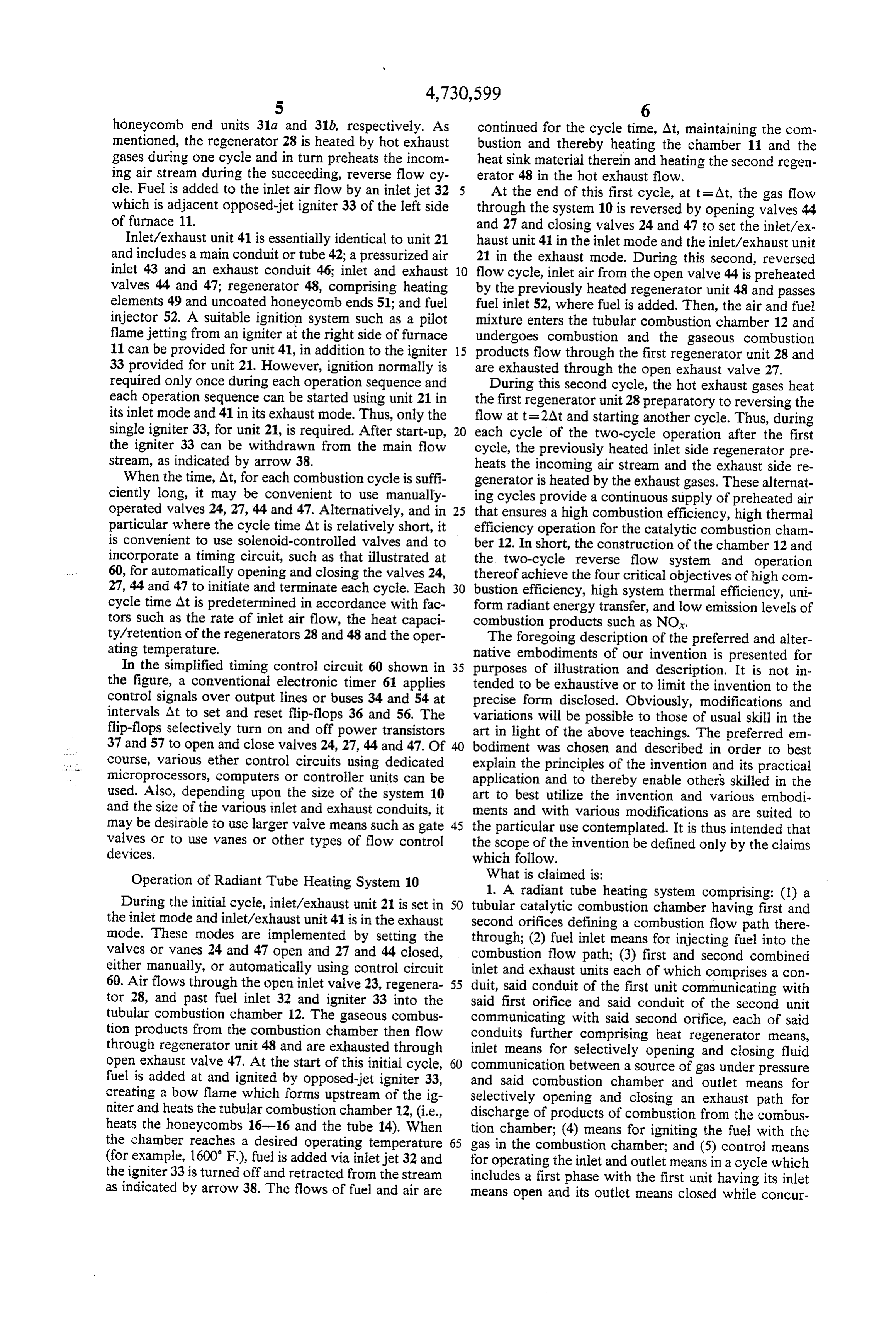
honeycomb end units 31a and 31b, respectively. As continued for the cycle time, At, maintaining the com mentioned, the regenerator 28 is heated by hot exhaust bustion and thereby heating the chamber 11 and the gases during one cycle and in turn preheats the incom heat sink material therein and heating the second regen ing air stream during the succeeding, reverse flow cy erator 48 in the hot exhaust flow. cle. Fuel is added to the inlet air flow by an inlet jet 32 At the end of this first cycle, at t = At, the gas flow which is adjacent opposed-jet igniter 33 of the left side through the system 10 is reversed by opening valves 44 of furnace 11. and 27 and closing valves 24 and 47 to set the inlet/ex Inlet/exhaust unit 41 is essentially identical to unit 21 haust unit 41 in the inlet mode and the inlet/exhaust unit and includes a main conduit or tube 42; a pressurized air 21 in the exhaust mode. During this second, reversed inlet 43 and an exhaust conduit 46; inlet and exhaust 10 flow cycle, inlet air from the open valve 44 is preheated valves 44 and 47; regenerator 48, comprising heating by the previously heated regenerator unit 48 and passes elements 49 and uncoated honeycomb ends 51; and fuel fuel inlet 52, where fuel is added. Then, the air and fuel injector 52. A suitable ignition system such as a pilot mixture enters the tubular combustion chamber 12 and flame jetting from an igniter at the right side of furnace undergoes combustion and the gaseous combustion 11 can be provided for unit 41, in addition to the igniter 15 products flow through the first regenerator unit 28 and 33 provided for unit 21. However, ignition normally is are exhausted through the open exhaust valve 27. required only once during each operation sequence and During this second cycle, the hot exhaust gases heat each operation sequence can be started using unit 21 in the first regenerator unit 28 preparatory to reversing the its inlet mode and 41 in its exhaust mode. Thus, only the flow at t=2At and starting another cycle. Thus, during single igniter 33, for unit 21, is required. After start-up, 20 each cycle of the two-cycle operation after the first the igniter 33 can be withdrawn from the main flow cycle, the previously heated inlet side regenerator pre stream, as indicated by arrow 38. heats the incoming air stream and the exhaust side re When the time, At, for each combustion cycle is suffi generator is heated by the exhaust gases. These alternat ciently long, it may be convenient to use manually ing cycles provide a continuous supply of preheated air operated valves 24, 27, 44 and 47. Alternatively, and in 25 that ensures a high combustion efficiency, high thermal particular where the cycle time At is relatively short, it efficiency operation for the catalytic combustion cham is convenient to use solenoid-controlled valves and to ber 12. In short, the construction of the chamber 12 and incorporate a timing circuit, such as that illustrated at the two-cycle reverse flow system and operation 60, for automatically opening and closing the valves 24, thereof achieve the four critical objectives of high com 27, 44 and 47 to initiate and terminate each cycle. Each 30 bustion efficiency, high system thermal efficiency, uni cycle time At is predetermined in accordance with fac form radiant energy transfer, and low emission levels of tors such as the rate of inlet air flow, the heat capaci combustion products such as NO.
ty/retention of the regenerators 28 and 48 and the oper The foregoing description of the preferred and alter ating temperature. native embodiments of our invention is presented for In the simplified timing control circuit 60 shown in 35 purposes of illustration and description. It is not in the figure, a conventional electronic timer 61 applies tended to be exhaustive or to limit the invention to the control signals over output lines or buses 34 and 54 at precise form disclosed. Obviously, modifications and intervals. At to set and reset flip-flops 36 and 56. The variations will be possible to those of usual skill in the flip-flops selectively turn on and off power transistors art in light of the above teachings. The preferred em 37 and 57 to open and close valves 24, 27, 44 and 47. Of 40 bodiment was chosen and described in order to best course, various ether control circuits using dedicated explain the principles of the invention and its practical microprocessors, computers or controller units can be application and to thereby enable others skilled in the used. Also, depending upon the size of the system 10 art to best utilize the invention and various embodi and the size of the various inlet and exhaust conduits, it ments and with various modifications as are suited to may be desirable to use larger valve means such as gate 45 the particular use contemplated. It is thus intended that valves or to use vanes or other types of flow control the scope of the invention be defined only by the claims devices. which follow.
Operation of Radiant Tube Heating System 10 What is claimed is:
1. A radiant tube heating system comprising: (1) a
During the initial cycle, inlet/exhaust unit 21 is set in 50 tubular catalytic combustion chamber having first and the inlet mode and inlet/exhaust unit 41 is in the exhaust second orifices defining a combustion flow path there mode. These modes are implemented by setting the through; (2) fuel inlet means for injecting fuel into the valves or vanes 24 and 47 open and 27 and 44 closed, combustion flow path; (3) first and second combined either manually, or automatically using control circuit inlet and exhaust units each of which comprises a con 60. Air flows through the open inlet valve 23, regenera 55 duit, said conduit of the first unit communicating with tor 28, and past fuel inlet 32 and igniter 33 into the said first orifice and said conduit of the second unit tubular combustion chamber 12. The gaseous combus communicating with said second orifice, each of said tion products from the combustion chamber then flow conduits further comprising heat regenerator means, through regenerator unit 48 and are exhausted through inlet means for selectively opening and closing fluid open exhaust valve 47. At the start of this initial cycle, 60 communication between a source of gas under pressure fuel is added at and ignited by opposed-jet igniter 33, and said combustion chamber and outlet means for creating a bow flame which forms upstream of the ig Selectively opening and closing an exhaust path for niter and heats the tubular combustion chamber 12, (i.e., discharge of products of combustion from the combus heats the honeycombs 16-16 and the tube 14). When tion chamber; (4) means for igniting the fuel with the the chamber reaches a desired operating temperature 65 gas in the combustion chamber; and (5) control means (for example, 1600 F), fuel is added via inlet jet 32 and for operating the inlet and outlet means in a cycle which the igniter 33 is turned off and retracted from the stream includes a first phase with the first unit having its inlet as indicated by arrow 38. The flows of fuel and air are means open and its outlet means closed while concur
Page 7
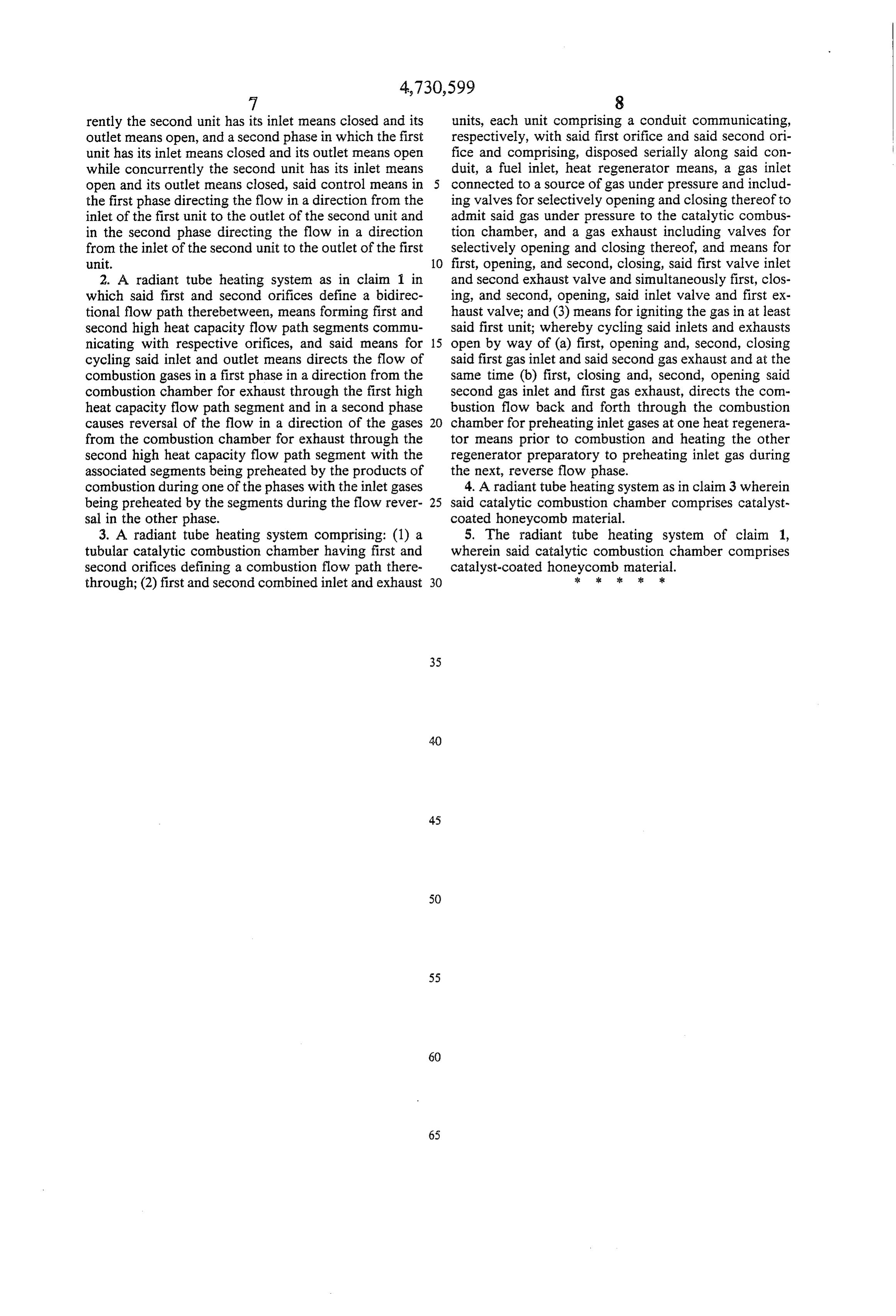
rently the second unit has its inlet means closed and its units, each unit comprising a conduit communicating, outlet means open, and a second phase in which the first respectively, with said first orifice and said second ori unit has its inlet means closed and its outlet means open fice and comprising, disposed serially along said con while concurrently the second unit has its inlet means duit, a fuel inlet, heat regenerator means, a gas inlet open and its outlet means closed, said control means in connected to a source of gas under pressure and includ the first phase directing the flow in a direction from the ing valves for selectively opening and closing thereof to inlet of the first unit to the outlet of the second unit and admit said gas under pressure to the catalytic combus in the second phase directing the flow in a direction tion chamber, and a gas exhaust including valves for from the inlet of the second unit to the outlet of the first selectively opening and closing thereof, and means for unit. 10 first, opening, and second, closing, said first valve inlet 2. A radiant tube heating system as in claim 1 in and second exhaust valve and simultaneously first, clos which said first and second orifices define a bidirec ing, and second, opening, said inlet valve and first ex tional flow path therebetween, means forming first and haust valve; and (3) means for igniting the gas in at least second high heat capacity flow path segments commu said first unit; whereby cycling said inlets and exhausts nicating with respective orifices, and said means for 15 open by way of (a) first, opening and, second, closing cycling said inlet and outlet means directs the flow of said first gas inlet and said second gas exhaust and at the combustion gases in a first phase in a direction from the same time (b) first, closing and, second, opening said combustion chamber for exhaust through the first high second gas inlet and first gas exhaust, directs the com heat capacity flow path segment and in a second phase bustion flow back and forth through the combustion causes reversal of the flow in a direction of the gases 20 chamber for preheating inlet gases at one heat regenera from the combustion chamber for exhaust through the tor means prior to combustion and heating the other second high heat capacity flow path segment with the regenerator preparatory to preheating inlet gas during associated segments being preheated by the products of the next, reverse flow phase.
combustion during one of the phases with the inlet gases 4. A radiant tube heating system as in claim 3 wherein being preheated by the segments during the flow rever 25 said catalytic combustion chamber comprises catalyst sal in the other phase. coated honeycomb material.
3. A radiant tube heating system comprising: (1) a 5. The radiant tube heating system of claim 1, tubular catalytic combustion chamber having first and wherein said catalytic combustion chamber comprises second orifices defining a combustion flow path there catalyst-coated honeycomb material. through; (2) first and second combined inlet and exhaust 30 : : se : sk
Provenance
- Collection
- Cited prior art
- Original PDF
- patentimages.storage.googleapis.com →
- Filed
- 1986-09-04
- Pages
- 7
- Method
- pdftotext (the PDF's own text layer) + pdftoppm 300dpi page scans
- Source
- Google Patents bibliographic record
- Granted
- 1988-03-15
- Inventors
- Robert M. Kendall; John P. Kesselring; Michael A. Lukasiewicz; John J. Lannutti; Richard J. Schreiber; GTI Energy
- Transcribed from
- patentimages.storage.googleapis.com →