patent · US5932885
Thermophotovoltaic electric generator
3 August 1999
Page 1 — bibliographic record
United States Patent 19 11 Patent Number: 5,932,885 DeBellis et al. (45) Date of Patent: Aug. 3, 1999 54) THERMOPHOTOVOLTAIC ELECTRIC Noreen, D.L., et al., “High Power Density ThermoPhoto GENERATOR voltaic Energy Conversion', The First NREL Conference on Thermophotovoltaic Generation of Electricity, Copper 75 Inventors: Crispin L. DeBellis; Mark V. Scotto, Mountain, CO, 1994, pp. 119-131. both of North Canton, Ohio; John D. Nelson, R.E., “Thermophotovoltaic Emitter Development', Malloy, III, Goode, Va.; Stephen W.
Scoles, Lynchburg, Va.; Donald L. The First NREL Conference on Theremophotovoltaic Gen Hindman, Forest, Va.; Jeffrey A. eration of Electricity, Copper Mountain, CO, 1994, pp. Rogers, Canton, Ohio 80-95.
73 Assignee: McDermott Technology, Inc., New Holmquist, G.A., et al., “Laboratory Development TPV Orleans, La. Generator.” The Second NREL Conference on Thermopho tovoltaic Generation of Electricity, Colorado Springs, CO, 21 Appl. No.: 08/858,335 1995, pp. 138-161. 22 Filed: May 19, 1997 Singh, S.S., “Design of a High Temperature Gas-Fired Heating System Utilizing Ceramics', Industrial Heating, (51) Int. Cl. .................................................. F21H 5/00 Nov., 1988, pp. 18–20. 52 U.S. Cl. ....................... 250/493.1; 136/253; 431/115;
432/182 Pernisz, U.C., et al., “Silicon Carbide Emitter and Burner 58 Field of Search ......................... 250/493.1; 136/253; Elements for TPV Converter”, The First NREL Conference 431/115; 432/182 on Thermophotovoltaic Generation of Electricity, Copper
Saraf, D.B., et al., “Design of TPV Generator with a Durable
Selective Emitter and Spectrally Matched PV Cells”, The 4.584,426 4/1986 Nelson .................................... 136/253 Second NREL Conference on Thermophotovoltaic Genera 4,707,560 11/1987 Hottel et al. ... 136/253 tion of Electricity, Colorado Springs, CO, 1995, pp. 98-108. 4,750,943 6/1988 Nelson .................................... 136/253 4,826,426 5/1989 Nelson .................................... 431/100 Coutts, T.J., et al., “A Review of Recent Advances in 4,836,862 6/1989 Pelka et al. ... ... 136/253 Thermophotovoltaics”, The 25th IEEE Conference, Wash 4,877.553 10/1989 Diederich ...... ... 252/492 ington, DC, May 1996. Entire paper. 4,976,606 12/1990 Nelson ...................................... 431/79 5,066,339 11/1991 Dehlsen ... ... 136/253 (List continued on next page.) 5,092,767 3/1992 Dehlsen ... ... 432/181 5,137.583 8/1992 Parent et al... ... 136/253 5,312,521 5/1994 Fraas et al. ....... ... 136/253 Primary Examiner Jack I. Berman 5,356,487 10/1994 Goldstein et al. ... 136/253 Attorney, Agent, or Firm-R. J. Edwards; Eric Marich 5,360,490 11/1994 Nelson .......... ... 136/253 5,383,976 1/1995 Fraas et al. ... 136/253 57 ABSTRACT 5,439,532 8/1995 Fraas ......... ... 136/253 5,512,108 4/1996 Noreen ...... ... 136/253 Athermally integrated burner/emitter/recuperator (BER) for 5,512,109 4/1996 Fraas et al. ... 136/253 a thermophotovoltaic (TPV) electric generator achieves 5,551,992 9/1996 Fraas ..... ... 136/253 improved energy efficiency using either liquid or gaseous 5,560,783 10/1996 Hamlen ................................... 136/253 fuels. A mixed ceramic and metallic alloy heat eXchanger, OTHER PUBLICATIONS together with a high temperature emitter, achieves increased Fraas, L.M. et al., “Fundamental Chracterization Studies of energy density in a compact and lightweight assembly. GaSb Solar Cells”, The 22nd IEEE Photovoltaic Specialists
Conference, IEEE, New York, NY, 1991, pp. 80–89. 20 Claims, 13 Drawing Sheets
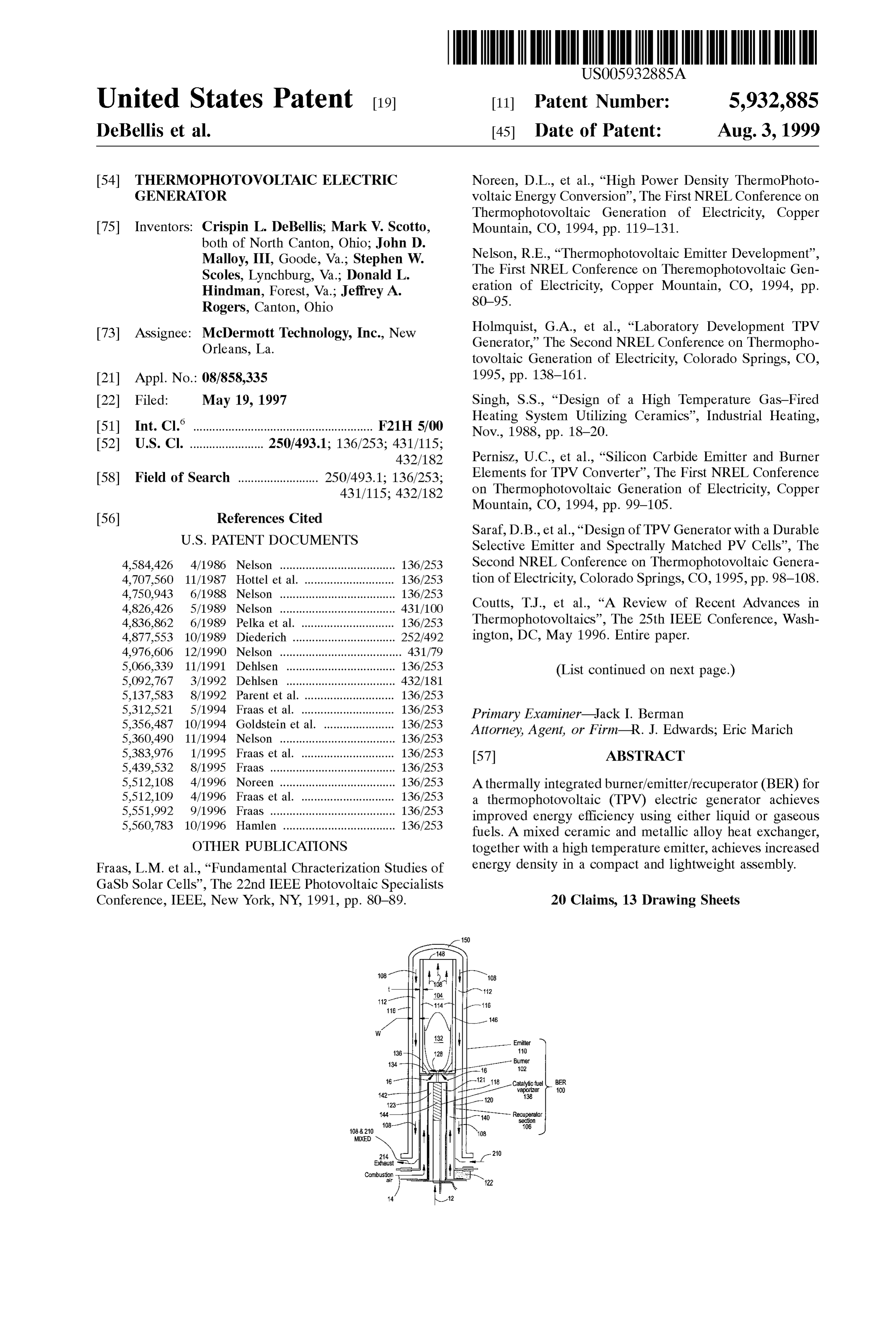
Burne
8-|-ZY-1-121 catalytic fuel BER
sign
MIXED Exhaust
All
Combustion Fl
Page 2
OTHER PUBLICATIONS Schroeder, K.L., et al., “An Experimental Investigation of Fraas, L.M. et al., “SiC IR Emitter Design for Thermopho Hybrid Kerosene Burner Configurations for TPV Applica tovoltaic Generators', The Second NREL Conference on tions”, The First NREL Conference on Thermophotovoltaic Thermophotovoltaic Generation of Electricity, Colorado Generation of Electricity, Copper Mountain, CO, 1994, pp. Springs, CO, 1995, pp. 488-494. 106-118.
Fraas, L.M. et al., “Development of a Small Air-Cooled
Midnight Sun Thermophotovoltaic Electric Generator', The McAlonan, M., et al. “Burner System for a Thermoelectric Second NREL Conference on Thermophotovoltaic Genera tion of Electricity, Colorado Springs, CO, 1995, pp. Generator, American Institute of Aeronautics and Astro 128-133. nautics, Inc., 1987, pp. 1962-1968. Menchen, W.R., “Development of a 0.1 kW Thermoelectric
Power Generator for Military Applications”, American Vinton, B., “Ceramic Radiant Tube System Speeds Batch Chemical Society, 1986, pp. 1361-1366. Furnace Recovery', Heat Treating, Feb. 1989, pp. 24-27.

Page 3
Drawing sheet — no readable text.
Page 4
Drawing sheet — no readable text.
Page 5
Drawing sheet — no readable text.
Page 6
Drawing sheet — no readable text.
Page 7
Drawing sheet — no readable text.
Page 8
Drawing sheet — no readable text.
Page 9
Drawing sheet — no readable text.
Page 10
Drawing sheet — no readable text.
Page 11
Drawing sheet — no readable text.
Page 12
Drawing sheet — no readable text.
Page 13
Drawing sheet — no readable text.
Page 14
Drawing sheet — no readable text.
Page 15
Drawing sheet — no readable text.
Page 16
THERMOPHOTOVOLTAC ELECTRIC failure of the emitter and other high temperature components GENERATOR of the system. However, the recent development of low bandgap Semiconductor materials allow the use of lower
FIELD OF THE INVENTION emitter temperatures. The gallium antimonide (GaSb) PV cells described by Fraas et al. in “Fundamental Character
The present invention relates generally to the field of 5 ization thermophotovoltaic (TPV) power generation and, more taic Specialists Studies of GaSb Solar Cells” (22nd IEEE Photovol particularly, to a thermally integrated burner/emitter/ Conference, IEEE, New York, 1991, pp. recuperator (BER) assembly for a TPV electric generator 80–89) are sensitive in the IR radiation out to 1.8 um (0.73 which is Suitable for use with liquid or gaseous fuels. eV). See FIG. 2.
Currently, Systems producing up to Several kilowatts are
BACKGROUND OF THE INVENTION under development. Commercial viability will be largely dependent on fabrication costs per unit of uSeable electrical
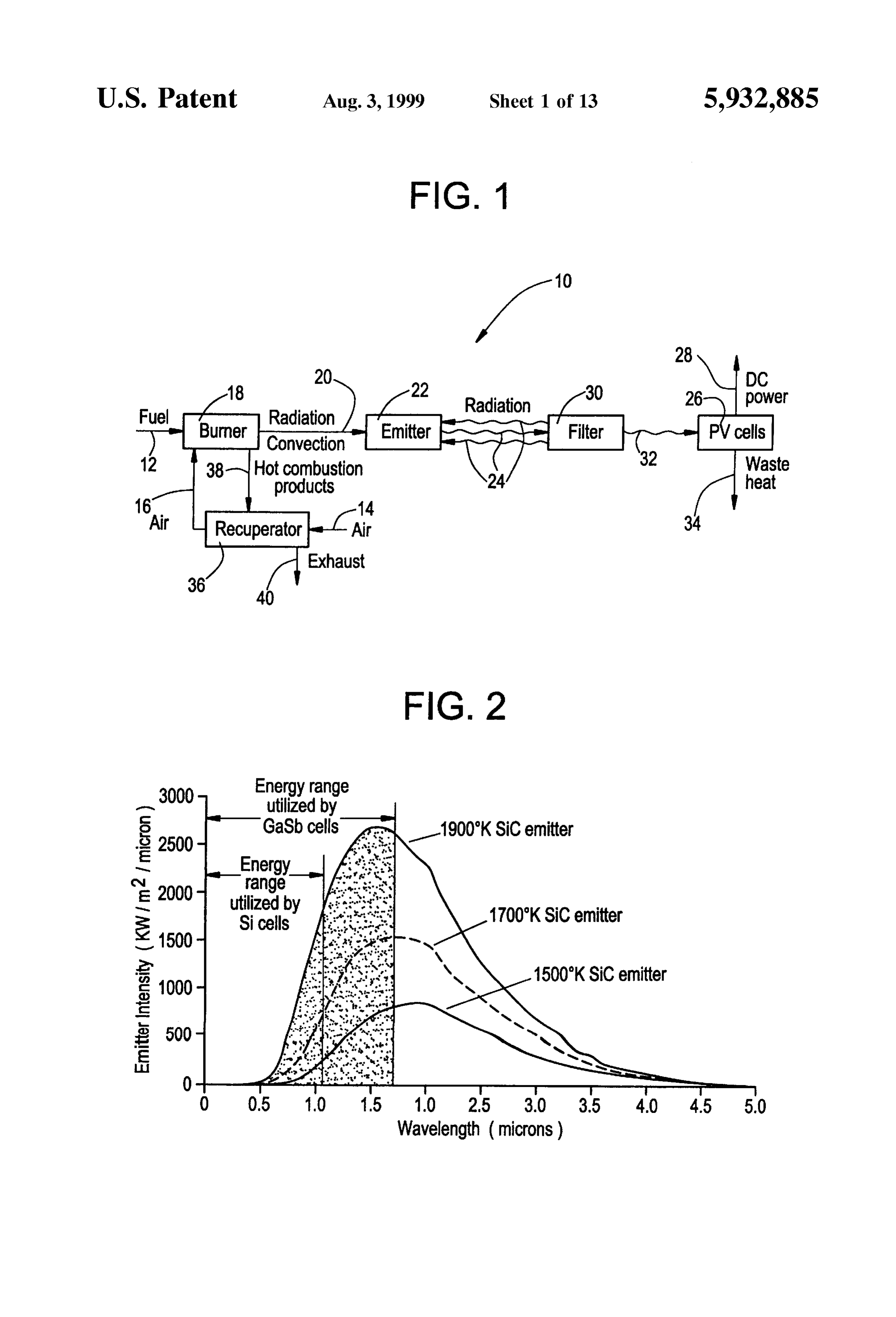
Photovoltaic (PV) cells are semi-conductor materials that power output. The low bandgap PV cells are expected to be generate an electric current when irradiated with an infra-red the most costly component of the TPV electric generator. (IR) photon source. The required temperature of the PV 15 The quantity of PV cells can be minimized with the design cells energy Source, the emitter, must be high enough to of energy efficient Systems, and with the development of emit significant radiation above the PV cell's characteristic emitter materials that can withstand higher temperatures to bandgap energy. Photons energetic enough to induce the produce higher useful photon fluxes. According to Noreen bandgap electron transitions in the PV material will generate and Du in “High Power Density Thermophotovoltaic Energy an electric current. In general, the photon or radiant emission Conversion” (The First NREL Conference on Thermopho of a material increases with temperature. Therefore, higher tovoltaic Generation of Electricity, Copper Mountain, Colo., emitter temperatures can substantially reduce the PV cell 1994, pp. 119-131), it was estimated that IR emitter sources area required to generate a given level of power. need to produce a Sufficient energy flux to generate approxi Solar photovoltaic technology utilizes relatively inexpen mately 7.5 to 10 Watts/cm to be commercially viable given sive Sicells in which the bandgap energy is 1.12 eV (1.11 25 current PV cell technology. This would allow fabrication of microns). The Sun is a high temperature source (6000 K.) compact, lightweight power Systems which can produce with much of its radiant emission above this bandgap Significant power at reasonable costs. These are only Some energy. A Solar cell is typically capable of generating only of the technical challenges that must be Surmounted to make about 0.02 Watts/cm’ in direct sunlight. This is due to the TPV technology a cost effective and energy efficient alter Sun's large distance from the earth which diminishes the native. Potential applications for Small portable power gen useful energy flux. Therefore, Solar photovoltaic power erators include: the military, commercial customers in Systems require relatively large Solar panels to collect Suf remote areas without easy access to a utility grid, cogen ficient power for residential dwellings and are confined to eration for residential and commercial dwellings, and Self locations and climates with Sufficient Sunlight. Reflective powered appliances.
Surfaces are often utilized in this technology to concentrate 35 Several R & D programs are under way to develop TPV the Sun's energy on the photovoltaic Surface. power System components. Much effort has gone into fab FIG. 1 illustrates a typical TPV system, generally desig ricating durable, Selective emitters that efficiently couple nated 10. A fossil fuel 12 is combined with preheated their radiance to the PV cell's bandgap energy. The tradeoff combustion air 14 for combustion in a burner 18. Radiative for higher energy efficiency utilizing Selective emitters is and convective heat transfer 20 from the combustion process 40 lower useful photon fluxes (power density). Broadband occurring at burner 18 elevates the temperature of an emitter (black body) emitters increase the photon convertible radi 22. The emitter 22 then radiates energy 24 to photovoltaic ance on the emitter which necessitates less PV cell area for (PV) cells 26 which convert incident radiant energy into a given power output. This significantly reduces System cost. electrical energy 28 in the form of a direct current or DC. However, PV cell conversion efficiency suffers. However, because PV cells 26 cannot convert all wave 45 Furthermore, out of band photon energy is also significantly lengths of light into electricity, optical filters 30 are used to higher with broadband emitters, and this radiant energy must filter outleSS useful wavelengths and permit desirable wave be recycled back to the emitter with elaborate spectral filters lengths 32 of radiant energy to strike the PV cells 26. This and reflectors to maintain high System efficiency. The debate is important because that portion of the incident energy between broadband and Selective emitters as a System choice absorbed by the PV cells 26 which is not converted into 50 continues. In the near term, and as discussed in the afore electricity must be removed as waste heat 34. A recuperator mentioned Noreen and Du reference, Some investigators feel 36 is used to boost the TPV system 10's efficiency by that broadband emitters may be more appropriate for the transferring a portion of the energy in hot combustion larger scale TPV systems that approach a kilowatt. The products 38 produced by burner 18 into incoming combus higher power densities will be necessary to keep costs down tion air 14 to produce the preheated combustion air 16, and 55 by minimizing the number of PV cells. prior to exhaust 40 of the combustion products 38 into the Selective emitter materials tend to have low thermal atmosphere. conductivities and are Susceptible to thermal Stresses. For Development efforts on TPV technologies go back to the this reason much of the Selective emitter development has early 1960s. Recently renewed interest in TPV has occurred taken the approach of fabricating fibrous porous emitters on with the development of more efficient lower bandgap PV 60 which a fossil fuel flame is Stabilized. This design approach cell designs that can be coupled with lower temperature IR provides excellent thermal coupling with the flame. AS a emitter Sources. It is now in the realm of possibility to result, emitter materials quickly approach the flame tem generate Sufficiently high emitter temperatures with fossil perature despite the low thermal conductivity. Fibers can fuel combustion, and to fabricate emitter materials that can also bend and thus thermal Stresses can be relieved. withstand these temperatures. To use Silicon cells efficiently 65 However, mechanical durability is poor. See for example, would require emitter temperatures greater than 2000 K. Nelson, “Thermophotovoltaic Emitter Development” (The This high temperature would result in rapid degradation and First NREL Conference on Thermophotovoltaic Generation
Page 17
of Electricity, Copper Mountain, Colo., 1994, pp. 80-95) long, emits inward to a 2 inch cylinder that Supports six (6) and Holmquist et al., “Laboratory Development TPV Gen separate % inch wide InGaAs PV strips with a bandgap of erator” (The Second NREL Conference on Thermophoto 0.6 eV. Inside the cylindrical PV cell support, a porous metal Voltaic Generation of Electricity, Colorado Springs, Colo., heat exchanger utilizes water at one (1) liter per minute to 1995, pp. 138-161) which describe development efforts for cool the PV cells. Parabolic reflectors focus the emitter these Selective emitters, and which include Supported Con radiance on the PV cell strips. Aselective holmia emitter that tinuous Fiber Radiant Structures (SCFRS) in which a solid is of a durable thermal shock resistant design would be used, ceramic Support Structure is fabricated with an array of holes and electric power output densities of 1.5 to 1.75 W/cm’ in which Small fiber bundles are mounted with a ceramic were anticipated.
epoxy. This design replaces a Single large fibrous structure Laboratory work has also been performed in the devel with Several Small fibrous bundles and improves Strength. opment of conceptual designs for TPV electric generators. Other work includes flow through ceramic felts utilizing a As described above, Nelson has been leading work in the replication proceSS on a rayon felt mat. Both of these development of a gas fired system utilizing SCFRS. As approaches use YbO, as the Selective emitter material, and published by Coutts et al. in “A Review of Recent Advances Seek to improve spectral properties and increase resistance 15 in Thermophotovoltaics” (The 25th IEEE Conference, to mechanical and thermal Stresses. Both of these Washington, D.C., May 1996), these designs have a useable approaches require a transparent window between the emit radiance of 4W/cm for 160 W/cm of fuel input, and that ter and the PV cells to isolate them from the high tempera usable radiance values of even 6 W/cm has been achieved. ture products of combustion. This window must have high AS described by Holmquist et al., Supra, a methane/ temperature capabilities and/or be cooled. The most eco oxygen fired TPV generator is being developed that pro nomical choice for this material is quartz; however, with duced 2.4 kW at a claimed efficiency of 4.5%. The design high emitter temperatures, quartz windows must be cooled utilized a flow-through selective emitter fabricated from a which Significantly complicates the System and reduces ceramic oxide (ytterbia). The process utilized a replication efficiency. process to form a Selectively emitting felt which enclosed a Another approach for the emitter uses Solid monolithic or 25 horizontal cylindrical combustion chamber. The ceramic felt composite Structures where the emitting Surface forms a failed when flows rates exceeded 630 SCFH. Future design physical barrier between the PV cells and hot combustion goals included improving the characteristics of the felt gases. This approach usually utilizes a broadband emitter emitter to reduce pressure and temperature drop, evaluating Such as SiC. SiC ceramic tubes have undergone much long term Strength and emittance, and optimizing the com development work as IR heat Sources for industrial heating bustion and recuperation process to improve efficiency. applications. See for example, Singh “Design of a High U.S. Pat. Nos. 5,383,976 and 5,439,532 to Fraas et al. Temperature Gas-Fired Heating System Utilizing Ceramics' disclose various gas-fired TPV electric generators employ (Industrial Heating, November 1988, pp. 18-20) and Vinton ing SiC emitters. A variation on the SiC emitter tube design “Ceramic Radiant Tube System Speeds Batch Furnace known as a “spine disc burner/emitter' is described by Fraas Recovery” (Heat Treating, February 1989, pp. 24-27). SiC 35 et al. in “SiC IR Emitter Design for Thermophotovoltaic ceramic tubes are excellent gray body emitters with emit Generators” (The Second NREL Conference on Thermo tance values close to 0.9 over a significant energy range photovoltaic Generation of Electricity, Colorado Springs, including the IR. SiC also has a high thermal conductivity. Colo., 1995, pp. 488-494) which improves the conversion Therefore, SiC ceramic tube emitters exhibit excellent ther efficiency of chemical energy to emitter radiance. See also mal shock resistance, and the thermal resistance through the 40 Fraas, et al. “Development of a Small Air-Cooled Midnight monolithic layer to the emitting Surface is minimized. The Sun Thermophotovoltaic Electric Generator” (The Second maximum operating temperature of SiC is approximately NREL Conference on Thermophotovoltaic Generation of 2000 K. As described in Pernisz, et al. “Silicon Carbide Electricity, Colorado Springs, Colo., 1995, pp. 128-133), Emitter and Burner Elements for a TPV Converter” (The which describes a TPV system that generates a power output First NREL Conference on Thermophotovoltaic Generation 45 of 137 Watts.
of Electricity, Copper Mountain, Colo., 1994, pp. 99-105), Schroeder et al. in “An Experimental Investigation of Some investigators are developing innovative approaches to Hybrid Kerosene Burner Configurations for TPV Applica the fabrication of SiC burner elements for TPV applications. tions” (The First NREL Conference on Thermophotovoltaic Utilizing organic siloxanes as precursors, additional Generation of Electricity, Copper Mountain, Colo., 1994, additives, and careful control over the pyrolysis Step, these 50 pp. 106-118), describes laboratory investigations which investigators have achieved considerable flexibility in the coupled flow-through emitters to liquid fired burners. The physical characteristics of SiC forms. With the ability to method of atomization for this low fuel input burner (<1 control density and porosity, and high emittance (20.84), kg/hr) utilized ultrasonics. As described by Menchen in SiC was deemed an excellent material candidate for broad “Development of a 0.1 kW Thermoelectric Power Generator band emitting burner elements. 55 for Military Applications” (American Chemical Society, Conceptual designs for Systems utilizing broadband and 1986, pp. 1361-1366) and by McAlonan et al. in “Burner Selective emitters have been patented. See, for example, U.S. System for a Thermoelectric Generator” (American Institute Pat. No. 4,836,862 to Pelka et al., drawn to a combustor/ of Aeronautics and Astronautics, Inc., 1987, pp. reactor for a TPV proceSS employing recuperation of energy 1962-1968), this atomization approach was used earlier in from the products of combustion. 60 the development of Small portable thermoelectric power In Saraf et al., “Design of a TPV Generator with a Durable systems for the U.S. Army.
Selective Emitter and Spectrally Matched PV Cells” (The It is thus clear that further improvements in TPV energy Second NREL Conference on Thermophotovoltaic Genera conversion efficiency and energy power density are needed tion of Electricity, Colorado Springs, Colo., 1995, pp. before TPV electric power generation can be brought out of 98-108), a TPV generator design is proposed that operates 65 the laboratory and put to practical, commercial use. The at 1100° C. to generate 250 watts of useable electric power, present invention provides improvements to the burner/ A cylindrical emitter, 6 inches in diameter and 10 inches emitter/recuperator aspects of TPV systems.
Page 18
S 6
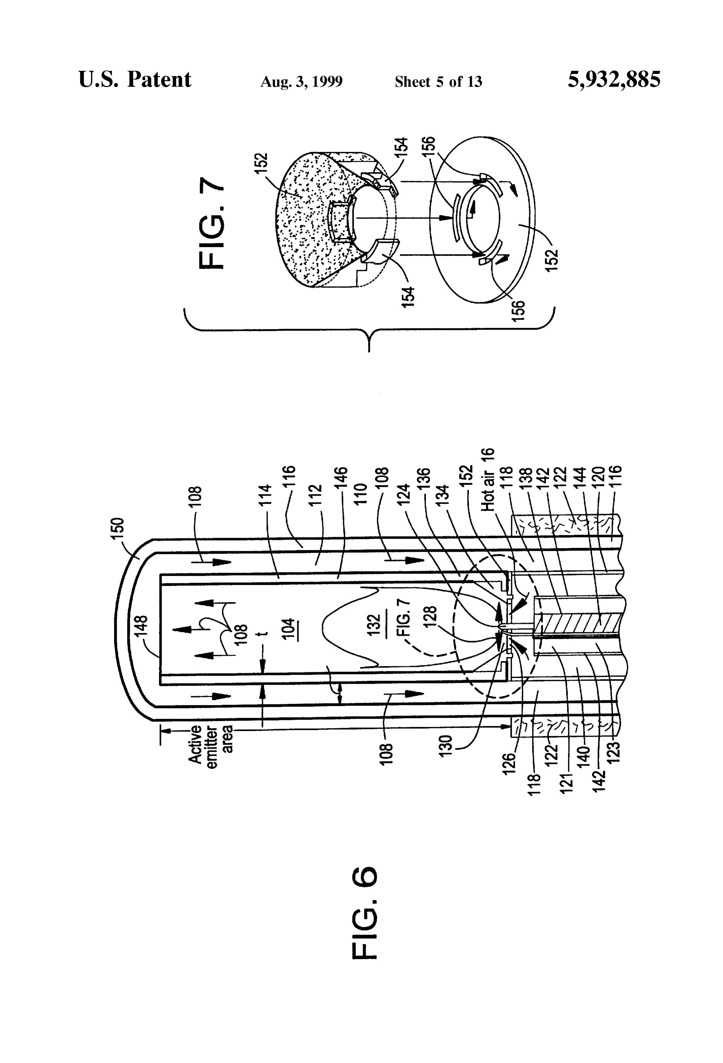
SUMMARY OF THE INVENTION FIG. 7 is an enlarged Schematic perspective view, partly The present invention is drawn to various aspects of in section, of a portion of the BER combustion chamber of components useful in TPV electric generator apparatus. FIG. 6;
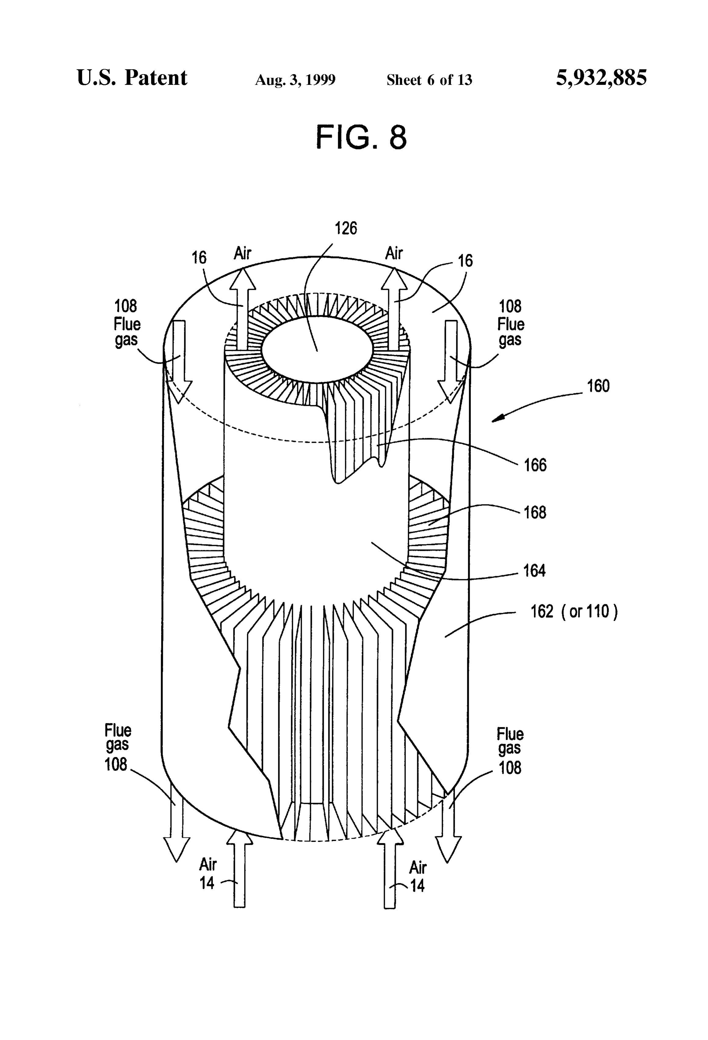
More particularly, a thermally integrated burner/emitter/ FIG. 8 is a Schematic perspective View, partly in Section, recuperator (BER) is described for use in a TPV electric of a heat eXchanger/recuperator used in the BER according generator which achieves improved energy efficiency and to the present invention;
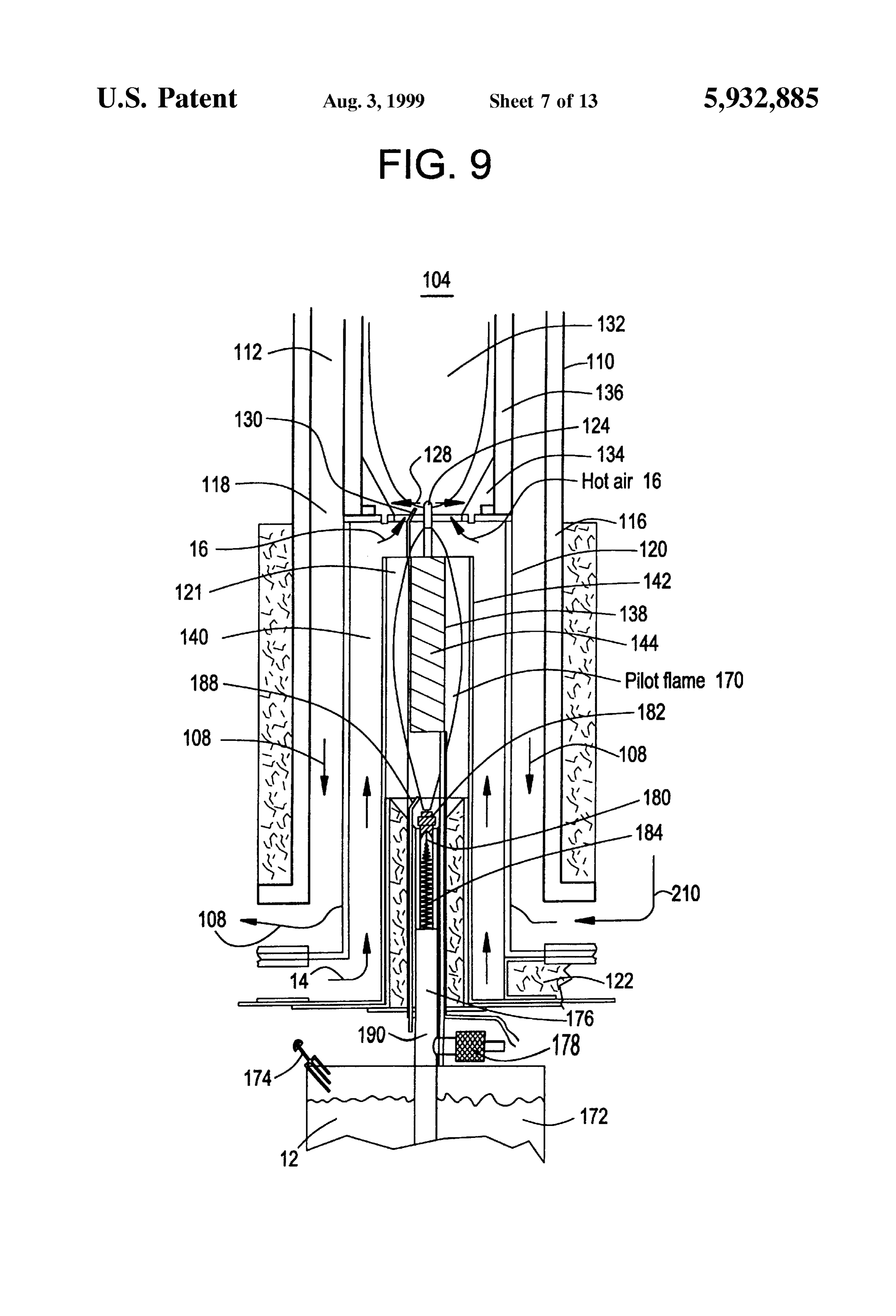
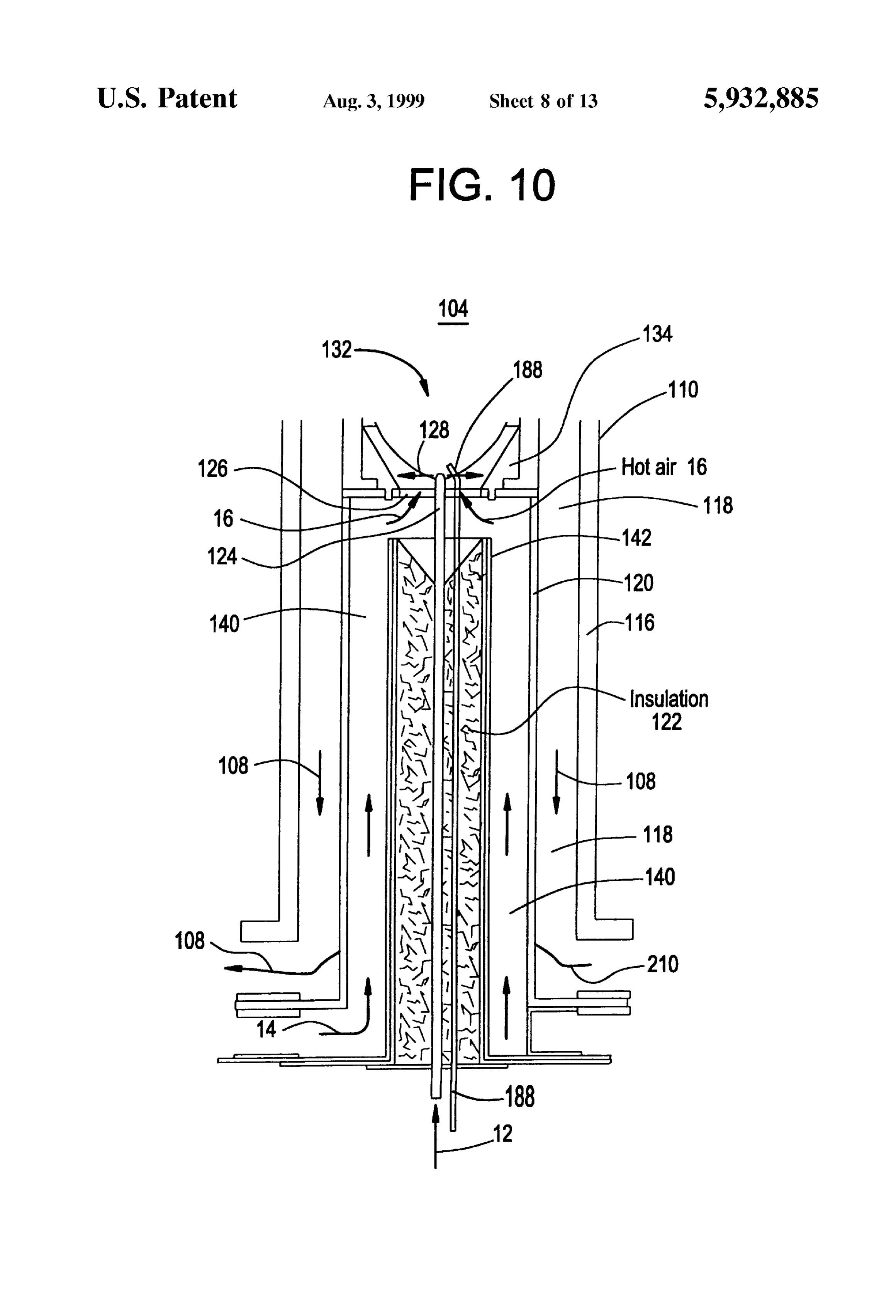
which can utilize either liquid or gaseous fuels. The liquid FIG. 9 is a schematic sectional view of an alternative fuels include but are not limited to DF-2 or JP-8 while the embodiment of a liquid fueled burner used in the BER gaseous fuels include but are not limited to propane or according to the present invention; natural gas. The thermally integrated BER achieves FIG. 10 is a schematic sectional view of an alternative improved energy efficiency. A mixed ceramic and metallic embodiment of a gaseous fueled burner used in the BER alloy heat eXchanger, together with a high temperature according to the present invention;
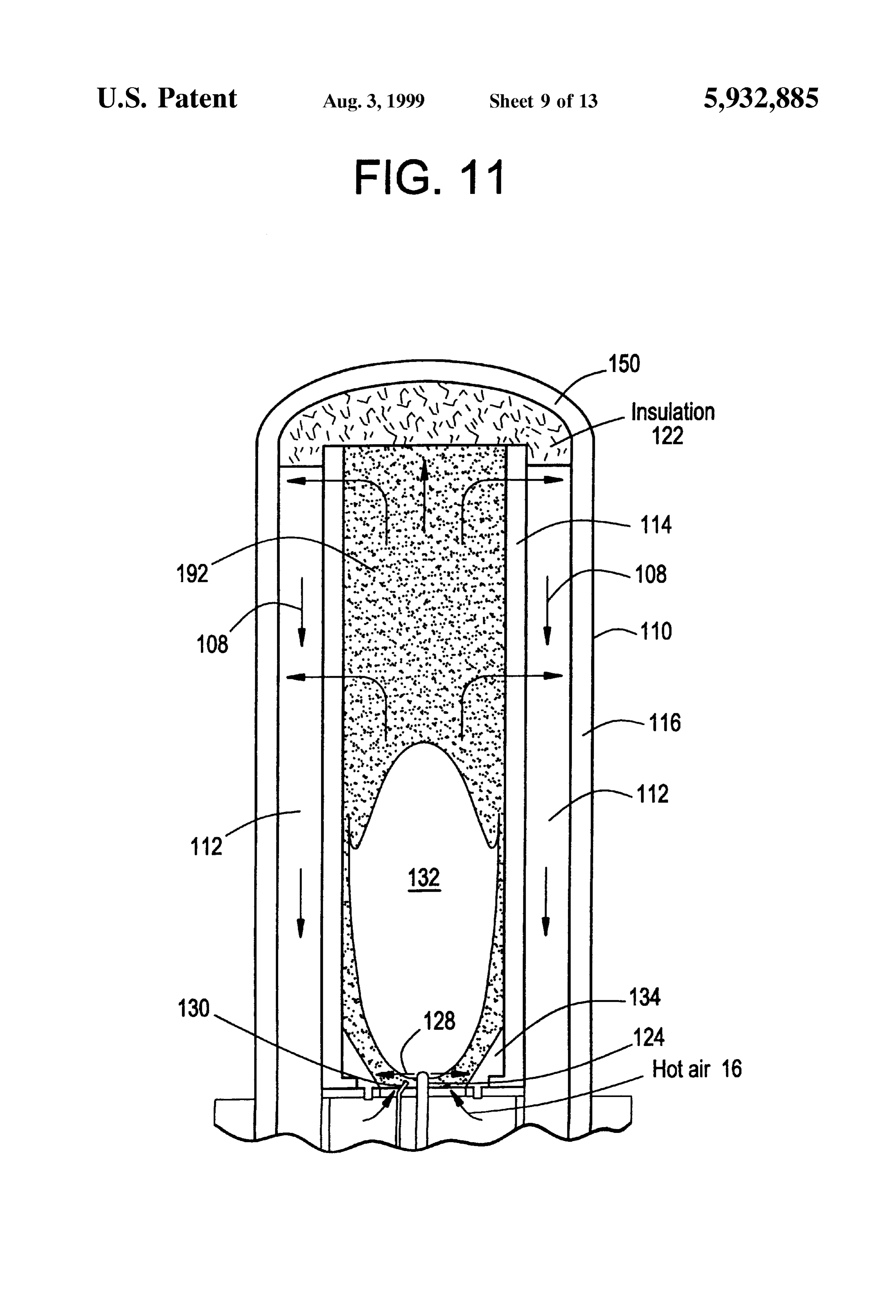
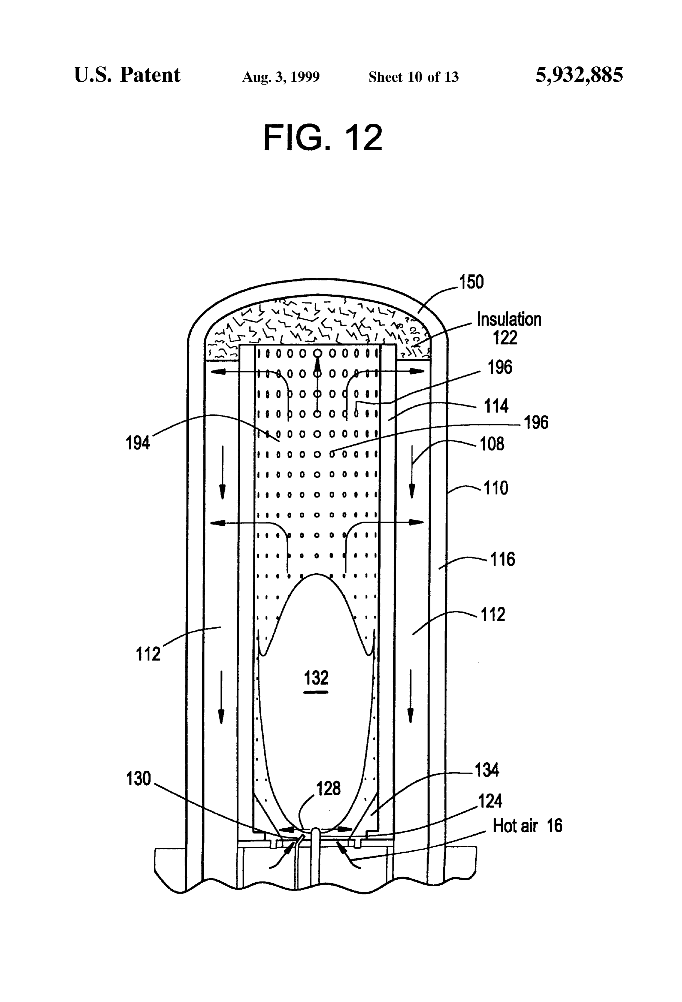
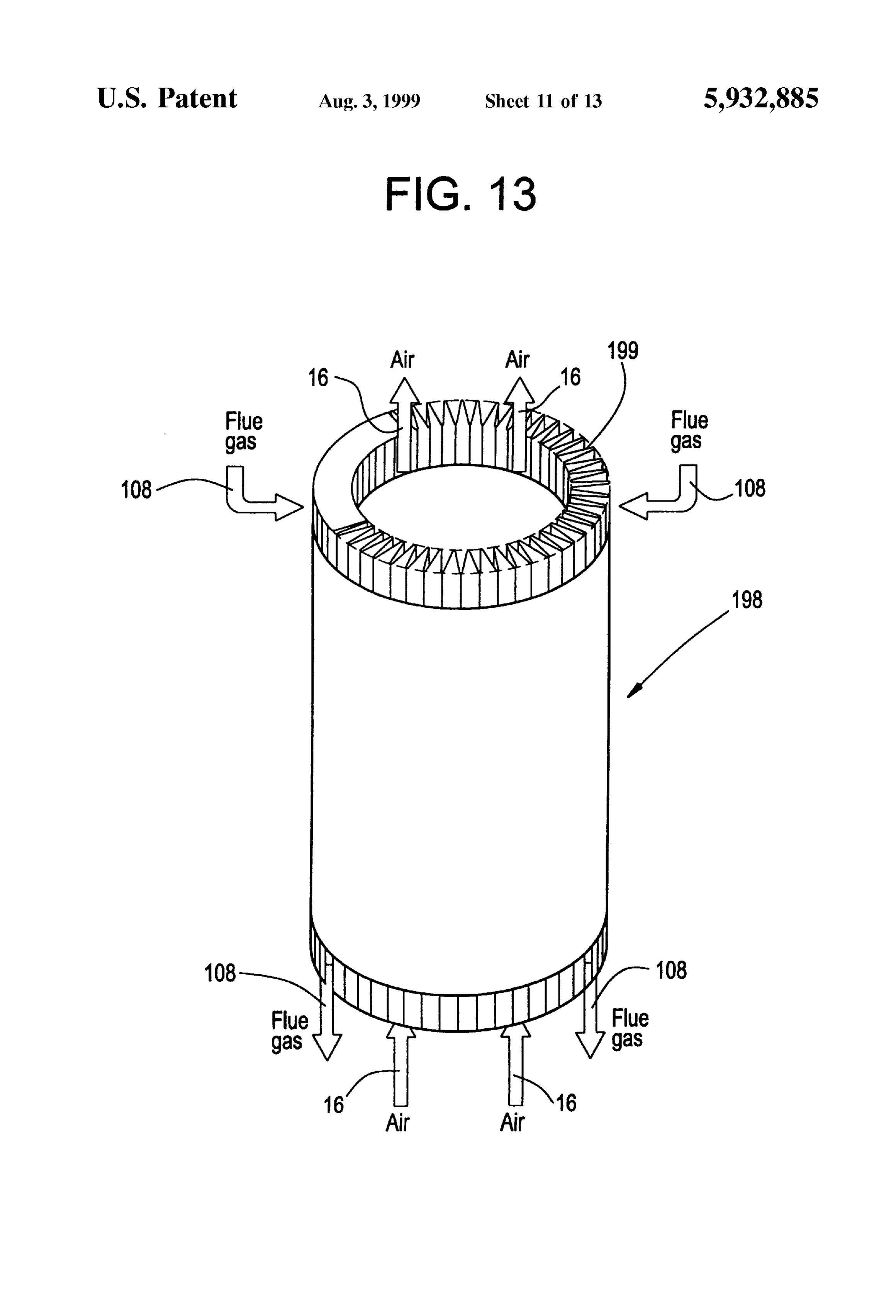
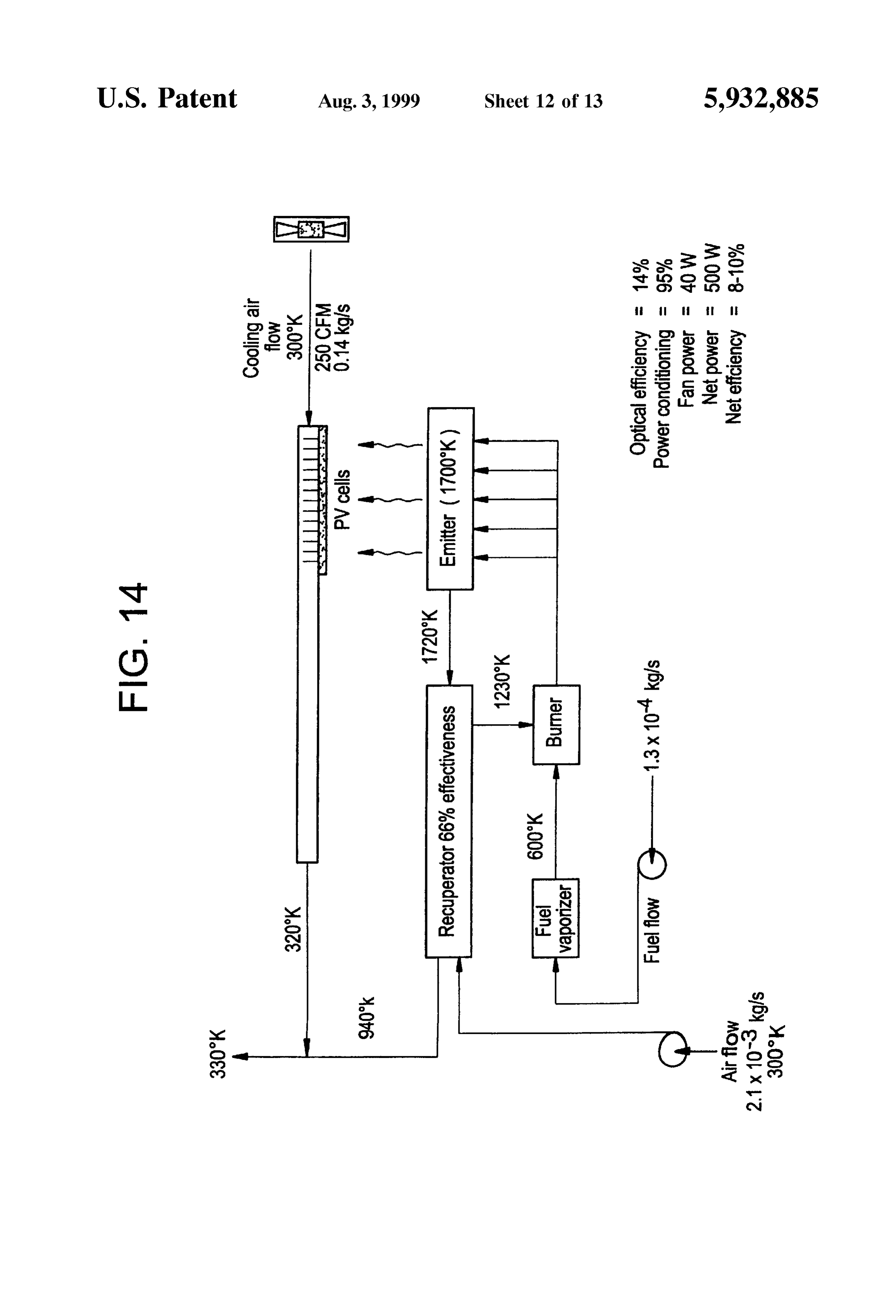
emitter, achieves increased energy density with low parasitic FIG. 11 is a schematic sectional view of an alternative power drain resulting in a compact and lightweight assem 15 embodiment of a combustion chamber used in the BER bly. according to the present invention; Accordingly, one aspect of the present invention is drawn FIG. 12 is a schematic sectional view of another alterna to a thermally integrated burner/emitter/recuperator (BER) tive embodiment of a combustion chamber used in the BER for a thermophotovoltaic (TPV) electric generator, compris according to the present invention; ing a radiant combustion chamber means having an inlet for admission of air and fuel and an outlet for exhaust of hot FIG. 13 is a Schematic perspective View, partly in Section, combustion products. A burner means provides air and fuel of another embodiment of a heat eXchanger/recuperator used to the inlet of the radiant combustion chamber means for in the BER according to the present invention; combustion therein. Counterflow recuperator means, located FIG. 14 is a schematic block diagram illustration of the adjacent to the burner means, preheats the air with the hot 25 performance of a TPV system employing the BER of the combustion products exhausted from the radiant combustion present invention;
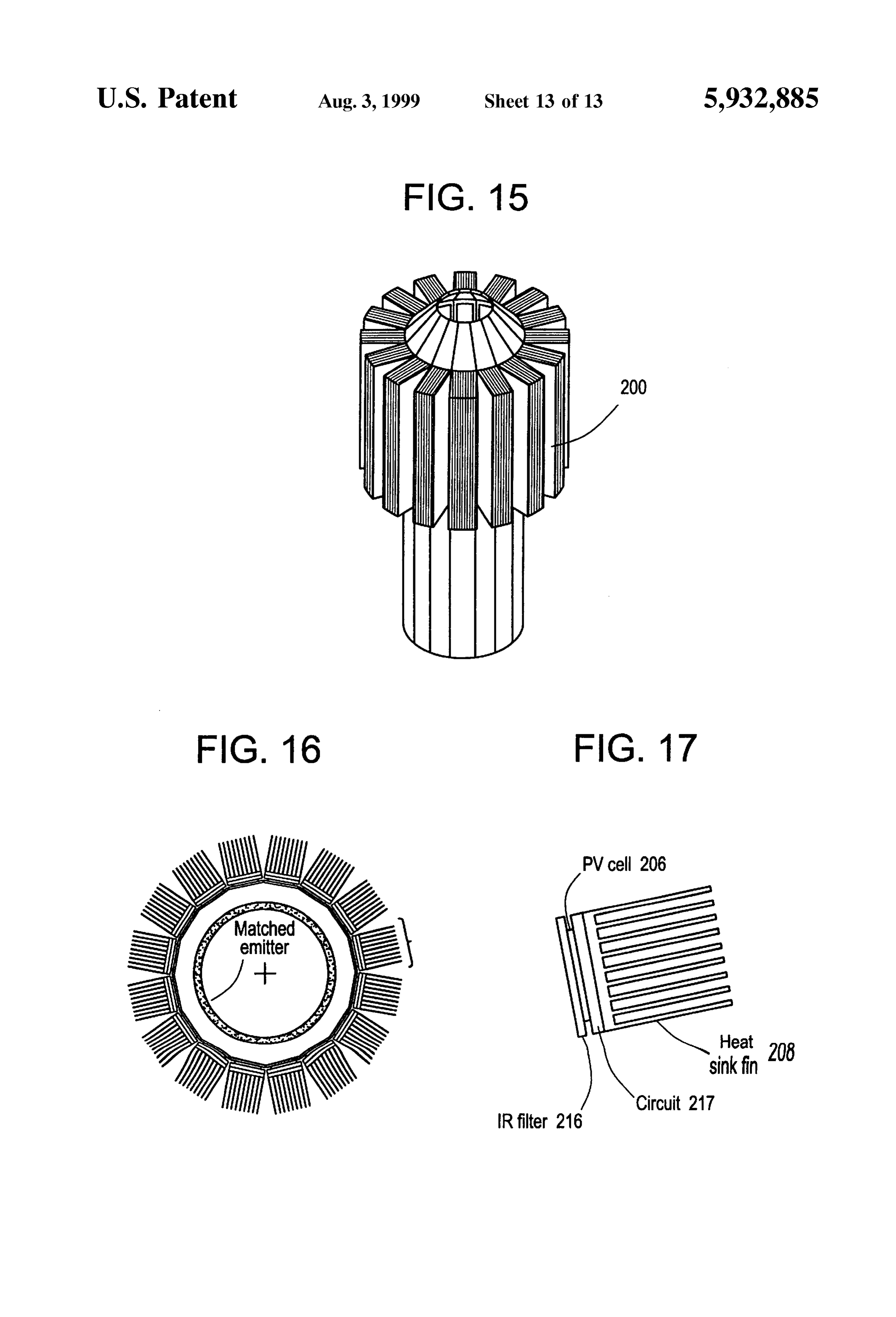
chamber means. Parallel flow fuel vaporizer/recuperator FIG. 15 is a schematic perspective illustration of a power means, located within the counterflow recuperator means, converter assembly (PCA) useful in combination with the are provided for preheating and vaporizing the fuel with the BER according to the present invention; preheated combustion air prior to providing Same to the FIG. 16 is a plan view of the PCA of FIG. 15; and burner means. Finally, emitter means for radiating photons FIG. 17 is an enlarged, schematic view of a converter when heated by the radiant combustion chamber means and module used in the PCA of FIG. 16. the hot combustion products are provided, the emitter means
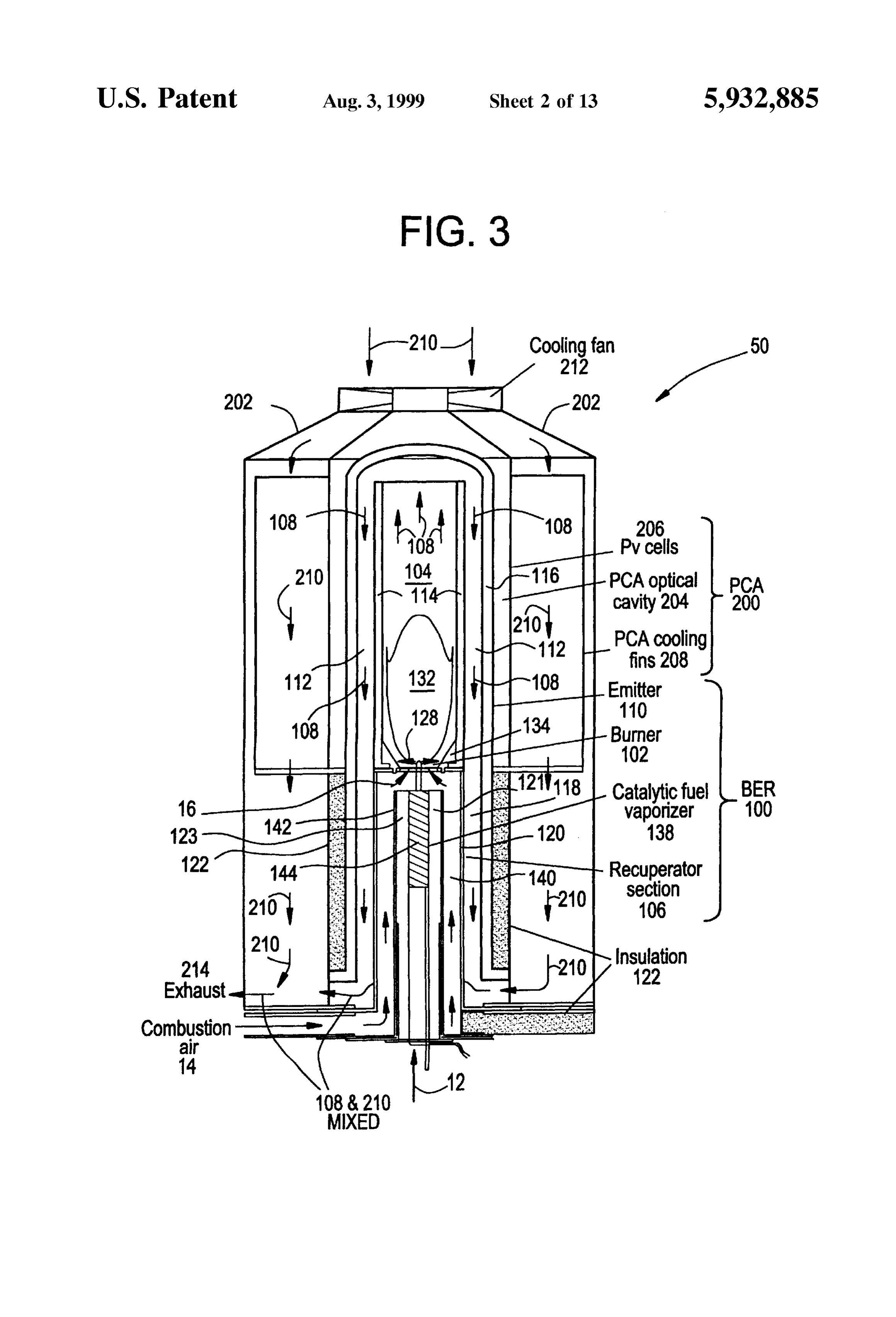
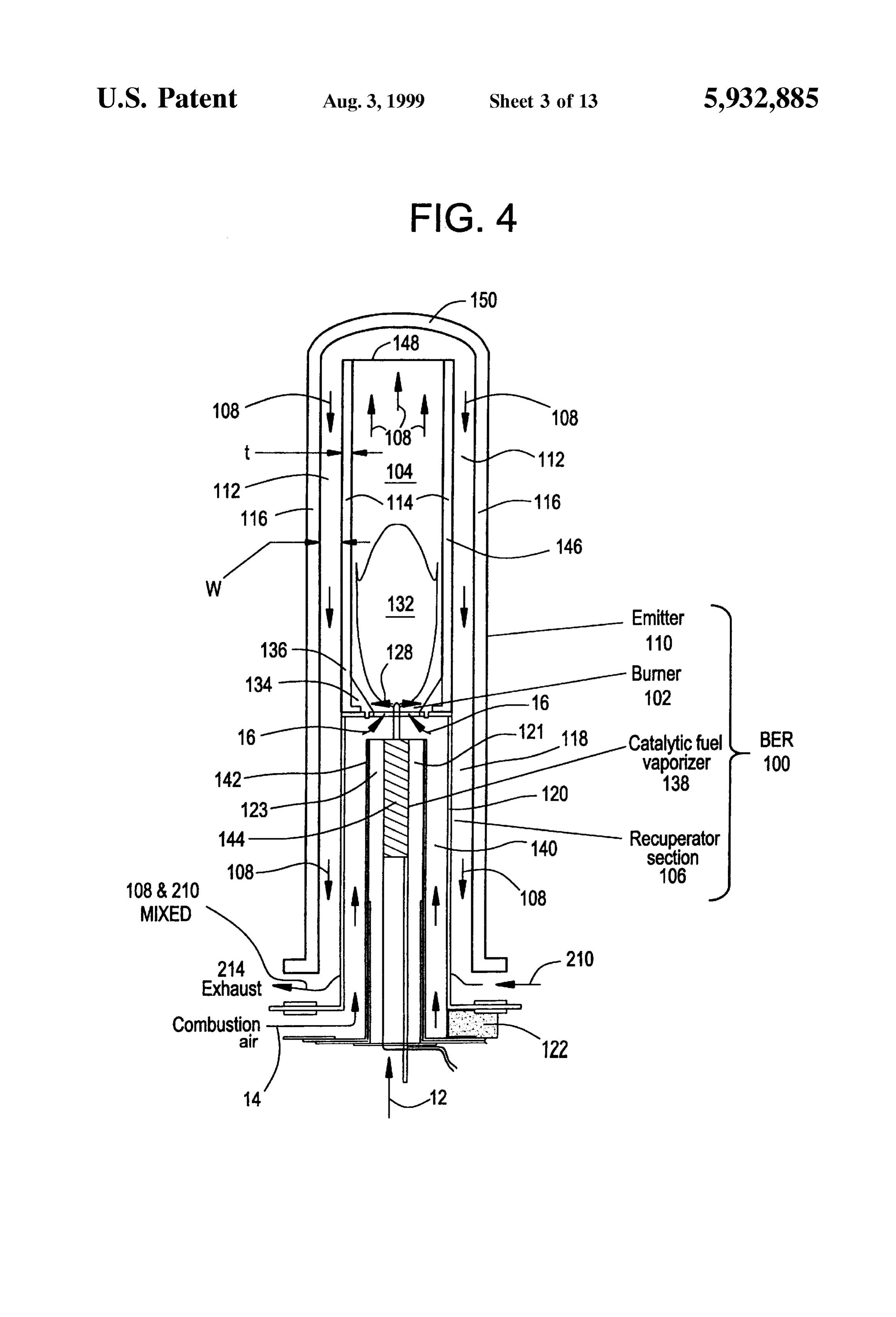
Surrounding and cooperating with the radiant combustion DESCRIPTION OF THE PREFERRED chamber means and the counterflow recuperator means So as 35 EMBODIMENTS to convey the hot combustion products along a wall of the emitter to heat it as the hot combustion products are con alsReferring to the drawings generally, wherein like numer veyed from the outlet of the radiant combustion chamber throughout the the designate same or functionally similar elements several drawings, and to FIGS. 3 and 4 in means to the counterflow recuperator means. particular, there is shown a thermophotovoltaic (TPV) elec Another aspect of the present invention is drawn to a BER 40 tric generator, generally designated 50, which utilizes gas which is simple in design, rugged in construction, and eous or liquid fossil fuels to generate electric power. The economical to manufacture.
TPV generator 50 is comprised of two major Subassemblies,
The various features of novelty which characterize the a burner/emitter/recuperator (BER) assembly, generally des invention are pointed out with particularity in the claims ignated 100 and hereafter referred to as BER 100, and a annexed to and forming a part of this disclosure. For better 45 power converter assembly (PCA), generally designated 200. understanding of the invention, its operating advantages and The BER 100 is substantially cylindrical and includes a Specific benefits attained by it uses, reference is made to the burner 102 for combusting liquid or gaseous fuel 12 with accompanying drawings and descriptive matter in which preheated combustion air 16 in a radiant combustion cham preferred embodiments of the invention are illustrated. ber 104 located above the burner 102. A counterflow recu BRIEF DESCRIPTION OF THE DRAWINGS 50 perator section 106 provided at a lower end of the BER 100 In the drawings: Surrounds the burner 102 and associated components described
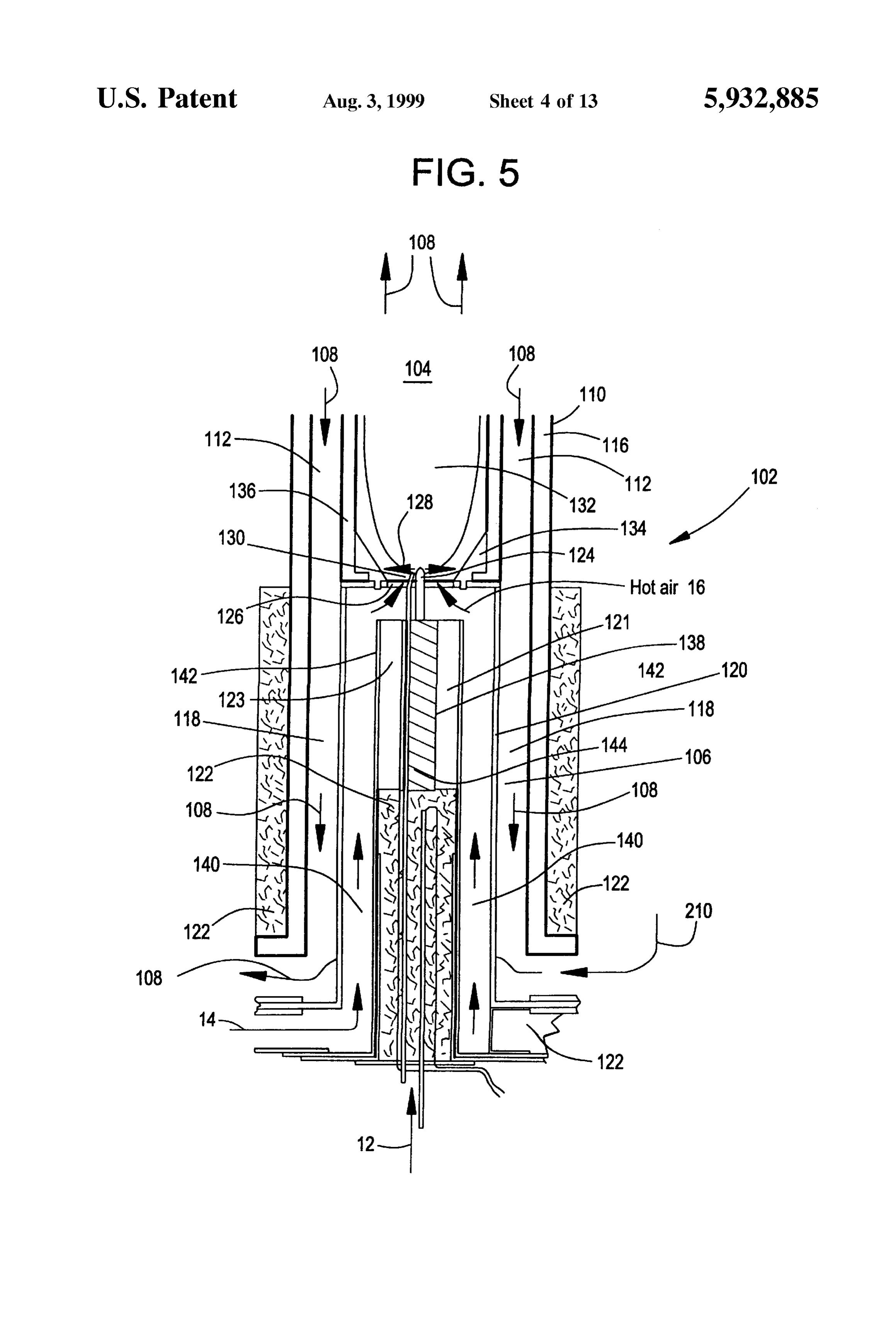
FIG. 1 is a schematic illustration of the components of a from the radiant infra uses hot combustion products (gases) 108 typical TPV system; combustion chamber 104 to preheat incom FIG. 2 is a graph illustrating the relative performance of 55 100. A parallel flow14 recuperator ing combustion air provided at a lower end of the BER 121 provided inside of silicon (Si) and gallium antimonide (GaSb) PV cells emitter counterflow recuperator Section 106 uses preheated com intensity as a function of incident radiation wavelength; bustion air 16 to vaporize liquid fuel 12 upstream of the FIG. 3 is a schematic sectional view of a TPV electric burner 102. An emitter 110 surrounding both the burner 102 generator employing the BER of the present invention; and radiant combustion chamber 104 is heated by the hot FIG. 4 is a schematic sectional view of the BER of FIG. 60 combustion gases 108 exiting from the radiant combustion 3; chamber 104 to a specified temperature. The emitter 110 is FIG. 5 is a schematic sectional view of a lower portion of impervious to gas flow through its walls. The hot combus the BER of FIGS. 3 and 4 illustrating a fuel vaporizer/burner tion gases 108 flow through an annular passageway 112 according to the present invention; created between a wall 114 of the radiant combustion FIG. 6 is a Schematic Sectional view of an upper portion 65 chamber 104 and a wall 116 of the emitter 110 to accomplish of the BER of FIGS. 3 and 4 illustrating a combustion this heating. The hot combustion gases 108 then proceed chamber of the BER according to the present invention; into a continuation 118 of the annular passageway 112,
Page 19
formed between a wall 120 of the recuperator section 106 energy must be recycled back to the emitter 110 using and the wall 116 of the emitter 110. Air 14 for combustion optical filters 216 (not shown in FIG. 3; see FIG. 17). In flows up along one side of the wall 120 on the inside of the addition, reflective coatings (not shown) on Some Surfaces recuperator section 106 while the hot combustion gases 108 minimize waste heat loSS and allow more low energy pho flow downwardly along the other side of the same wall 120. tons to be recycled back to the emitter 110. The PCA optical Heat transfer from the hot combustion gases 108 through the cavity 204 is thus more particularly defined by the emitter wall 120 preheats the incoming combustion air 14 on the 110, optical filters 216, reflective coatings (not shown) and opposite side of the wall 120. Likewise, preheated combus the PV cells 206 and their circuit components 217. tion air 16 passes through the parallel flow recuperator The required BER 100 emitter 110 surface area will Section 121 and transferS heat acroSS wall 142 to vaporize depend on the optical efficiency of the PCA optical cavity incoming liquid fuel stream 12. Thus it will be seen that the 204, the PV cell 206 efficiency, and the targeted power radiant combustion chamber 104, the burner 102, the coun output, and would thus be Scaled to the capacity require terflow recuperator section 106, the parallel flow recuperator ments of the System.
section 121, and the emitter 110 are substantially coaxial The BER 100 is designed to be as energy efficient as with one another. It will further be seen that air flows 15 possible. The BER 100's energy efficiency is the fraction of through the counterflow recuperator section 106 and the fuel 12 energy utilized to heat the emitter 110 to its specified combustion products flow through the radiant combustion temperature. The counterflow recuperator 106 and parallel chamber 104 predominantly in a first direction, while hot flow recuperator 121 are essential components for recover combustion products counterflow along the wall 116 of the ing energy that would otherwise be wasted when the com emitter 110 from the outlet of the radiant combustion bustion products 108 exit the system. The recuperator 106 is chamber 104 to the counterflow recuperator section 106 a heat eXchanger that transferS this energy to the combustion predominantly in a Second direction. Insulation 122 is pro air 14. The parallel flow recuperator 121 is a heat eXchanger vided at various locations around the recuperator section 106 that transferS this energy to the fuel 12. By employing liquid to maximize the thermal efficiency. fuel 12 in the BER 100 according to the present invention, The PCA 200 is also substantially cylindrical and Sur 25 additional opportunities for thermal efficiency improvement rounds the BER 100, and is provided with an outer shell 202. are thus available. This is because the liquid fuel 12 must be The PCA 200 is spaced from the emitter 110 by a specified preheated and vaporized prior to combining it with pre distance to create PCA optical cavity 204, generally defined heated air 16 for combustion. The liquid fuel 12 thus by the emitter 110 and a surrounding array of PV cells 206. represents an additional “heat sink” to which the heat in the FIG. 15 illustrates the PCA 200 without the shell 202 for hot combustion products 108 can be applied via the fuel clarity purposes and FIG. 16 is a plan view thereof. In the vaporizer 138. More particularly, the parallel flow recupera PCA 200, the emitter 110 radiates preferentially in a given tor section 121 transfers heat from the preheated combustion energy band to excite the PV cells 206 to generate electricity. air 16 to the fuel 12, and thus the overall thermal efficiency To cool the PV cells 206, PCA cooling fins 208 are provided is improved. The exhaust 214 temperature is also lowered, on each of the PV cells 206 and cooling air 210 is forced 35 further reducing the thermal Signature of the device. downwardly across these PCA cooling fins 208 by cooling The means by which the burner 102’s energy release is fan means 212, preferably an axial flow fan. The cooling air coupled to the emitter 110 is also critical in determining the 210 flows downwardly within the shell 202 across the fins BER 100's energy efficiency. A more rapid energy transfer 208 to a lower portion of the TPV generator 50. This cooling mechanism between the hot combustion products 108 and air is then mixed and blended with the hot combustion gases 40 the emitter 110 will reduce the amount of fuel 12 required to 108 exiting from the recuperator section 106 before both are attain the Specified average emitter temperature. The energy exhausted to the atmosphere at 214. The combination of the transfer to the emitter 110 must also address the need for insulation 122 Surrounding the recuperator Section 106, the temperature uniformity along the emitter 110. cooling air 210 passing over the PCA cooling fins 208 and The present BER 100 has the following capabilities or recuperator section 106, the shell 202 surrounding the BER 45 features: 1) a burner 102 with liquid and gas-fired capability; 100 and PCA 200, and the mixing of the hot combustion 2) reliable and stable flame ignition; 3) and rapid attainment gases 108 with the cooling air 210 prior to exhaust at 214, of steady state conditions. The preferred BER 100 involves produces a quiet, thermally integrated and insulated TPV liquid fuel 12 firing, with gas fuel 12 firing as a simplified generator 50 with a low thermal signature. The power from option. Rapid attainment of Steady State conditions will the TPV generator 50 is utilized to operate electronic equip 50 reduce Start-up energy requirements for liquid fuel 12 vapor ment (useable power), and to operate equipment necessary ization and operation of accessory equipment. The features for System operation Such as air fans, fuel pumps (not necessary to achieve reliable and efficient fuel firing are shown), and automated valves (also not shown) (parasitic presented below.
power loss). Fuel Vaporizer/Burner
In the PCA 200, the emitter 110 radiates a portion of its 55 Referring now to FIGS. 5 and 6, the preferred embodi energy in the IR (infrared radiation) region of the spectrum. ment of the burner 102 comprises a gas nozzle 124 which The photons are absorbed by the PV cells 206. Those rapidly entrains the preheated combustion air 16 provided photons above the cell's characteristic bandgap energy in the through an annular burner air opening 126. The gas nozzle IR can produce electricity with efficiencies up to approxi 124 generates Several fuel gas jets 128 that radially spread mately 30%. The remaining fraction of absorbed photons are 60 the fuel 12 into the radiant combustion chamber 104. The converted to heat. Since the PV cell 206's electrical con fuel jets 128 are ignited with a spark ignitor 130. In order to version efficiency is reduced at elevated temperature, the PV keep a resulting flame 132 in a lower portion of the radiant cell 206's support structure must be designed with a heat combustion chamber 104, the gaseous fuel jets 128 need to sink. In addition, the energy radiated by the emitter 110 flow out from the gas nozzle 124 nearly perpendicular to the below the PV cell 206's band gap energy cannot generate 65 incoming annular air flow 16 around the gas nozzle 124. In electricity. If this energy were absorbed it would also addition, a refractory, frustoconical burner quarl throat 134 generate heat. Therefore, to maintain high efficiency, this with a 15 to 45° angle, preferably 30, from its center axis
Page 20
is required. The refractory burner quarl throat 134 is pref If the catalytic fuel vaporizer 138 were simply a tube or erably a Small piece of high density, high temperature coil within which the fuel 12 boils, the generation of refractory that will facilitate flame stabilization by providing excessive heavy components might lead to a Smokey flame a hot Surface for flame attachment. The burner throat quarl and soot formation. Therefore, the preferred embodiment 134 also protects a lower portion 136 of the wall 114 of the uses the catalytic fuel vaporizer 138. Preferably, the catalyst radiant combustion chamber 104 from direct flame 132 is located within element 138, but it could also fill an annular impingement. The quarl 134 controls the flame 132 expan space 123 defined between wall 142 and element 138, in Sion and Swirl and prevents recirculation of hot flue gases to which case element 138 could readily be visualized as the close to the burner 102 face. The fuel 12 is injected radially aforementioned internal cartridge heater. The catalyst is in order to get quick mixing with the air 16 and to hold the intended to favor formation of lighter hydrocarbon fractions flame 132 low in the radiant combustion chamber 104. The from the liquid fuel 12 and minimize the potential for gas nozzle 124 is designed to impart a tangential Velocity excessive Soot formation and decreased combustion effi component and a Small axial Velocity component to the fuel ciency in the radiant combustion chamber 104. The light jet 128 velocity to prevent impingement on the burner throat hydrocarbon fractions formed by endothermic reactions quarl 134 that is too direct, and flame 132 stabilization that 15 provide an additional heat Sink to improve recuperative is too deep into the burner throat quarl 134. A combination energy recovery. The gas nozzle 124 at the downstream end of air 16 Swirl, fuel jet 128 geometry, and refractory burner of the vaporizer 138 is preferably made of ceramic and throat quarl 134 geometry will establish a well back mixed designed to operate at moderate pressures (approximately 3 flame 132 stabilized near (but not too close to) the burner to approximately 10 psig) to generate gaseous the fuel jets 102 face. These parameters can also be varied to position the 128 predominantly comprised of light hydrocarbon frac flame 132 within the combustion chamber 104 to achieve a tions. The resulting flame 132 will not form deposits on relatively uniform temperature profile along an active length internal Surfaces of the radiant combustion chamber 104. of the emitter 110 to enhance TPV performance. However, it may be determined that non-catalytic fuel For liquid fuels, (i.e. DF-2 or JP-8) it is preferred that a Vaporization may be necessary if catalyst deactivation and catalytic fuel vaporizer 138 precede and vaporize the liquid 25 bed plugging by coke formation within the bed becomes too fuel 12 provided to the gas nozzle 124. A crystalline alumi rapid. Thus the present invention contemplates that the fuel nosilicate (zeolite) catalyst will be preferably utilized in the vaporizer 138 could also be a simple thermal fuel vaporiza vaporizer heat exchanger 138 without added steam or air to tion device 138 that does not use a catalyst. Particular break down the fuel 12 into lighter fractions. Lighter hydro features of the radiant combustion chamber 104 are carbon fractions will burn more rapidly and cleanly in the described below.
radiant combustion chamber 104. Formation of lighter Combustion Chamber hydrocarbon fractions occurs via endothermic reactions that Referring to FIGS. 6 and 7, the radiant combustion provide an additional heat Sink for increased recuperation. chamber 104 illustrated contains the flame 132 and transfers Providing a Significant fraction of hydrogen and unsaturated fuel energy to the emitter 110 to raise it to a specified hydrocarbon gases gas will increase flame 132 velocities. 35 temperature. Extracting as much chemical energy as pos Cracking catalysts are Susceptible to gradual build-up of sible from the fuel 12 to heat the emitter 110 Surface is the coke in the catalyst bed which may diminish catalyst activity objective of the burner 102 and the radiant combustion over time. In addition, catalyst poisoning by Sulphur con chamber 104. However, achieving temperature uniformity taining compounds may occur. However, it is believed that over the emitter 110, and observing material temperature there are commercially available Zeolites which can proceSS 40 limitations are also very important design criteria. The JP-8 and DF-2 for hundreds of hours without significant preferred embodiment of the radiant combustion chamber coking or poisoning of the catalyst bed. 104 comprises two co-annular tubes. Combustion occurs The catalytic fuel vaporizer 138 will operate in the 500 within an inner combustion tube or radiator 146, having an K. to 600 K. temperature range. The heat exchanger/ upper open end 148. Tube 146 is also surrounded or recuperator 106 surrounds the catalytic fuel vaporizer 138. 45 enclosed within an outer tube which comprises the emitter Hot combustion air 16 flowing up through inner annular 110 itself. An upper end 150 of the emitter 110 tube is closed passageway 140 defined between an internal wall 142 and off so that the hot combustion products 108 flow out and recuperator wall 120 recovers heat from the hot combustion around the upper open end 148 of the inner tube 146, and exhaust 108. The hot air 16 heats the internal wall 142 Subsequently pass down the annulus 112 between the inner defining the parallel flow recuperator Section 121 of the heat 50 tube 146 and the emitter 110. This closed end 150 design exchanger/recuperator 106 which, in turn, will heat the makes it possible to secure the emitter 110 at the lower, cold catalytic fuel vaporizer 138 by conduction and/or radiative end. Cold end attachment eliminates the need for high heat transfer during Steady State operation. Inner wall 142 is temperature joints and allows the emitter 110 tube to expand positioned inside of the wall 120 Separating the two annular freely, thus lowering thermal StreSS and increasing reliabil passageways 118 and 140. The main liquid fuel 12 Supply 55 ity. The inner tube 146 is heated by the combustion gases (not shown) will require a fuel pump (not shown) to deliver 108 and radiates energy to the surrounding emitter 110. The the liquid fuel 12 at moderate pressures (approximately 3 to emitter 110 is also heated by convection from the combus approximately 10 psig) to the catalytic vaporizer 138. tion gases 108 flowing through the annulus 112. The hot During Start-up for liquid fuel 12 combustion, Some flame 132 in the lower portion of the inner tube 146 forming method of electrical heating will preferably be provided. The 60 radiant combustion chamber 104 causes that portion to catalytic fuel vaporizer 138 could be heated with a surround radiate more intensely to the emitter 110. In turn, the hot ing nichrome wire electric resistance heater 144 or an combustion gases 108 flowing in the annulus 112 are cooler internal cartridge heater. The heater 144 would initially be at this point producing less convective heat transfer to the run off power provided by a battery (not shown) until hot emitter 110, while the opposite effect happens at the upper heat eXchanger Surfaces in the recuperator 106 could take 65 end of the radiant combustion chamber 104. Through this over. The primary advantage of electrical heating is that it is design, the convective and radiation components of the heat easily amenable to automation and precise control. flux to the emitter 110 can be offset to achieve a uniform heat
Page 21
flux applied to the emitter 110. This in turn will produce a Heat Exchanger (Recuperator) uniform emitter temperature. Additional heat flux control to Ideally, ceramic materials which can withstand the high the emitter 110 can be achieved by varying the thickness t of combustion gas temperature would be used in the heat the radiator wall 114 and the width w of the annulus 112. exchanger/recuperator 106. However, reliable (long life) Also, the thermal resistance of the radiator 146 can be varied compact ceramic heat eXchangers may not be available in through the use of composite layers of low and high thermal the near-term. The present invention thus employs ceramics conductivity materials. Proper selection of the values of where they are needed (for the combustor chamber 104 and these design parameters, will again result in a relatively the emitter 110) and proven metallic structures for the uniform temperature profile along an active length of the majority of the recuperator section 106. Accordingly, FIG. 8 emitter 110 to enhance TPV performance. shows one embodiment of the recuperator system 106 of the The preferred material for the combustion chamber tube present invention. The recuperator section 106 preferably or radiator 146 and emitter 110 will be a dense silicon comprises a high-temperature, metallic alloy, compact carbide (SiC) for the following reasons. Several advanced (plate-fin) heat exchanger, generally designated 160, located SiC based ceramics are commercially available. They can be within an outer tube 162 advantageously made of ceramic, fabricated into a variety of shapes, and display Superior 15 possibly SiC. Outer tube 162 could be merely a continuation properties. Very dense, hard mechanically durable combus of the emitter 110 itself. Inner tube 164 would preferably be tion chamber parts can be fabricated with working tempera a high temperature alloy because it will be cooled from the tures as high as 2000 K. SiC also has a high thermal combustion air 14, 16 flowing on the inside. The fins 168 on conductivity relative to other ceramic materials. This lowers the air side would be metallic and be attached to the inner the Steady State operating temperature of the emitter 110 and tube 164. The fins 168 on the flue gas side would also be radiator 146. In addition, lower combustion gas tempera metallic and attached to the inner tube 164. The fins 168 on tures are necessary and less fuel 12 is required to drive the the flue gas Side would start at a location when the tem required energy transport through the emitter. Relative to perature of the flue gas 108 falls below the maximum metal other possible choices for ceramic materials, SiC also has a temperature. Thus in this embodiment, the counterflow high thermal Shock resistance making this material much 25 recuperator Section 106 comprises a compact plate fin heat leSS Susceptible to breakage during use. The high density exchanger having the inner tube 164 finned on both its inside materials also have relatively good mechanical shock resis and outside Surfaces, air 14 flowing in a first direction along tance. Emissivity is approximately 0.9 over a wide range of the inside Surface of the inner tube 164 and hot combustion useful wavelengths making SiC an excellent broadband products 108 counterflowing along the outside surface of the emitter. For these reasons, the broadband emitter approach inner tube 164 in a second direction. If a material like of a SiC emitter 110 is preferred. However, alternatives are Kanthal(F) (a high temperature alloy comprised of chromium presented and discussed below which utilize Selective emit 22%, aluminum 4-6% and the balance, iron) is used for the ter materials. inner tube 164 and fins 166, the maximum use temperature FIG. 7 illustrates a particular construction of the combus would be 1670 K. If Inconel were used, this temperature tion tube 146, burner quarl 134, and the recuperator 106 35 drops to 1300 K. The fins 166, 168 would be connected to which facilitates their assembly. The inner tube 146 is the inner tube 164 with high temperature braze or welding. fastened and Sealed to an upper recuperator plate 152 using To obtain a high efficiency TPV generator 50, a recupera the refractory burner quarl throat 134 at the base of the tor with a thermal effectiveness of 66% is required, achiev radiant combustion chamber 104. The burner quarl throat ing a preheat air temperature of 1200 K. The theoretical 134 is designed to attach the inner radiator tube 146 to the 40 performance of Such a System is Schematically represented top of the recuperator plate 152 by means of embedded high by FIG. 14. For a 500 watt, 24 volt DC TPV generator 50, temperature resistant, metallic, "L-shaped” pins 154 that can using JP-8 fuel, it is envisioned that the entire TPV generator be inserted through slots 156 in the upper recuperator plate 50 incorporating the BER 100 according to the present 152. A soft refractory layer (not shown) placed between the invention will be approximately 20 cm (8 in.) in diameter burner quarl 134 and the upper recuperator plate 152 would 45 and 50 cm (20 in.) high, not including any fuel tank or be provided for sealing. The pins 154 are fitted through the controls. It is estimated that the total System may weigh as slots 156 and the burner throat quarl 134 compresses the soft little as 7.5 kg (16.5 lb.) without fuel. This clearly illustrates insulating layer (not shown). Twisting the burner throat the compact and lightweight design for a TPV electric quarl 134 locks the L-shaped pins under the upper recupera generator 50 which can be obtained using the features of the tor plate to hold the assembly in place. 50 present invention. The recuperator must be compact and The radiant combustion chamber 104 isolates the PV cells have a low preSSure loss. A simple cylindrical recuperator 206 from the hot combustion products 108. This eliminates with no fins, by itself, cannot produce this effectiveness the need for a window as required in a porous burner design. regardless of length. The recuperator 106 and the burner/ Thus, the Over all System according to the present invention emitter 102/110 according to the present invention are thus is simpler and cooling requirements are lower because there 55 close coupled and thermally integrated to improve overall is no quartz window to cool. The lower cooling requirements System efficiency by lowering thermal losses. This close will also result in a more efficient system with lower coupling also simplifies gas passages and Sealing. In parasitic power for cooling fans and direct use of the energy addition, the recuperator 106 length can be varied to either absorbed off the window. increase efficiency or reduce weight. This design option will The placement of the burner throat quarl 134 relative to 60 trade off System efficiency for weight in a compact, low the active emitter area (illustrated in FIG. 6) is also crucial. preSSure drop design.
The active emitter area should start at a level above the Advantages of the Invention bottom of the burner throat quarl 134. If the active emitter A thermally integrated BER of the present invention can area is below this level, Significant amounts of thermal be used to produce an energy efficient, compact, lightweight energy can radiate out of the radiant combustion chamber 65 TPV power generator. High energy efficiency minimizes 104 directly into the recuperator 106. This energy “short fuel usage for a given level of power output. High efficiency circuit can significantly lower System thermal efficiency. is preferably achieved by:
Page 22
1) a lightweight, compact, high temperature ceramic chamber will generate lighter hydrocarbon fractions which and/or metallic heat eXchanger/recuperator 106, inte diminish the potential for Soot formation. Light hydrocarbon grated with a parallel flow heat eXchanger/recuperator fractions formed by endothermic reactions provide an addi 121; tional heat Sink to recuperate energy from combustion 2) a radiant combustion chamber 104 and burner 102 products. The added System Volume required for the pre design which effectively utilizes fuel energy to uni vaporization chamber will be neatly incorporated within the formly heat the emitter 110 to its operating tempera recuperator 106 which also provides the primary heat source ture; and for fuel vaporization at Steady State conditions. 3) a catalytic fuel vaporizer 138 that increases recuperated The advantages of the burner design are achievement of System heat and combustion intensity. rapid ignition, flame Stability, and rapid mixing utilizing: The SiC radiant combustion chamber 104 and 1) a frustoconical refractory burner throat quarl 134; (broadband) emitter 110 of the present invention provides 2) combustion air Swirl; and many advantages. Material durability and life expectancy 3) multiple gaseous fuel jets 128 at moderate pressure will be greatly improved. The emitter 110 forms an imper (approximately 3 to approximately 10 psig) primarily vious physical barrier between the hot combustion gases 108 15 radially injected into the radiant combustion chamber and the PV cells 206 which provides good shielding from 104 but also with tangential and Small axial velocity excessive heat without a quartz window and additional components to the fuel jet 128 velocity. The radiant combustion cooling for such a window. The emitter 110 tube is also frustoconical refractory burner chamber 104 is designed with a throat quarl 134 to shield the closed at the upper, hot end So that it can be Secured at the radiant combustion chamber 104 internals from direct flame cold end only. The primary radiant combustion chamber 104 impingement, and also acts as a fastening device for Sub design is simple and provides means to produce a uniform system components. The burner throat quarl 134 when emitter temperature. Use of Solid materials allows operation properly aligned with the emitter 110, prevents the short at higher emitter temperatures due to higher material dura circuit of energy out the recuperator 106. The quarl 134 bility. Higher temperature increases the emitted energy depth helps control the intensity of back mixing near the density and decreases required PV cell 206 area, weight, and 25 burner 102 face. The walls 114 of the combustion chamber cost for a given level of power production. The relatively 104 and the flame profile are designed to provide a uniform high thermal conductivity of SiC improves energy transfer heat flux to the emitter 110 and thus produce a uniform (fuel efficiency) from the radiant combustion chamber 104 emitter temperature along its active length. The radiator 146 through the emitter 110, lowers the working temperature of shape, thickness t, and the annular gap w between it and the internal combustion chamber Surfaces, and provides good emitter 110 can also be varied to promote temperature resistance to thermal StreSS. Although material issues may uniformity.
prevent the use of flow-through combustion chamber The recuperator 106 design utilizes a combination of components, options are provided for their use and dis ceramic and metallic materials in a unique high temperature, cussed below to potentially improve fuel efficiency. Mono high efficiency design that is Superior to an annular design lithic ceramicS Such as SiC are commercially available in 35 and can be built with conventional materials. The recupera cylindrical geometry. Although not unique to this invention, tor 106 is compact and has a low pressure loss. The this geometry improves the View factor between the emitter recuperator 106 and the burner/emitter 102/110 are close 110 and the PV cells 206, thereby minimizing end losses. coupled and thermally integrated to improve overall System The cylindrical geometry also provides an efficient means efficiency by lowering thermal losses. This close coupling for the PV cells 206 to dissipate heat outward through their 40 also Simplifies gas passages and Sealing. In addition, the support structure and PCA cooling fins 208. The cylindrical recuperator length can be varied to either increase efficiency design also simplifies the flow passages and improves the or reduce weight.
close coupling of the BER 100. While specific embodiments of the invention have been The invention includes a burner design capable of burning shown and described in detail to illustrate the application of a liquid fuel. Liquid fuel fired capability increases the 45 the principles of the invention, those skilled in the art will attractiveness and potential application of the technology. appreciate that changes may be made in the form of the The advantages of the disclosed burner design allow for invention covered by the following claims without departing reliable ignition, rapid start-up, Stable operation, and clean, from Such principles. For example, as Set forth immediately complete combustion of a liquid fuel. During Startup, the below, various changes in the form and construction of the primary design option initially utilizes battery power for fuel 50 burner, combustion chamber, and heat eXchanger/ Vaporization by electric resistance heating. This design is recuperator used in the present invention may be employed more conducive to automated control. in certain Situations.
Thermal pre-vaporization of the liquid fuel provides an Burner Options attractive alternative to ultraSonic atomization, because As illustrated in FIG. 9, a liquid fuel 12 fired pilot flame piezoelectric crystals utilized in Such nozzles cannot exceed 55 170 can be utilized to preheat the catalytic vaporizer 138 approximately 350 K. Therefore, extreme care must be until the heat exchanger/recuperator 106 provides this taken to thermally shield Such nozzles from a near adiabatic energy Source at Steady State operation. Although Still shown combustion environment. In addition, Such nozzles are in FIG. 9, this would allow one to replace the catalytic expensive. Additional advantages of pre-vaporization come Vaporizer 138's heating element 144, Significantly reducing from the fact that combustion can occur as a turbulent 60 Start-up requirements. Both constructions, however, could gaseous diffusion flame. This is more conducive to rapid be provided to provide redundancy and availability. The mixing, higher combustion intensity, flame ignition and pilot flame 170 would be started manually. Fuel flow would Stability relative to a liquid atomized flame. Complete com be supplied from a fuel tank 172 pressurized with a hand bustion will be possible with a more compact combustion operated pump 174. Therefore, a Smaller lightweight Start chamber design. The potential for Soot formation and coking 65 up battery (not shown) could be utilized with this setup. This on combustion chamber Surfaces will be diminished. In burner alternative will utilize a commercially available addition, the use of a Zeolite catalyst in the pre-vaporization components to produce the pilot flame 170.
Page 23
For the pilot flame, a fuel control assembly developed for can be used separately or in combination to produce radia Coleman(R) lanterns and stoves could be utilized. This type tion that is selective to the photovoltaic cell wave band. of fuel control assembly 176 allows for the combustion of Typically, the use of Selective emitters results in higher liquid type fuels from a cold Start by utilizing pressurized air system efficiency but lower power density. Matched emitters which becomes entrained with the liquid fuel. A potentially are being developed which emit like a blackbody above the useful fuel control assembly 176 is described in U.S. Pat. PV cell bandgap and are reflective below it. This is the best No. 4,522,582. As disclosed therein, a control knob 178 on alternative for producing high efficiency and high power the assembly opens a valve to initiate fuel flow to an outlet density.
fuel orifice. Turning the control knob 178 through a Heat Exchanger Options
Sequence of positions slides a tip cleaning needle 180 into A Second alternative design for the recuperator Section the fuel outlet orifice 182. Additional rotation partially opens 106 includes a compact alloy heat eXchanger made of a fuel inlet valve 184 allowing entrainment of air into the Kanthal(F) material with a fluted design, generally designated fuel. This action also gradually withdraws the needle 180 198, and as illustrated in FIG. 13. Kanthal(E) material has a acting as a flow restricting device from the fuel outlet orifice temperature limit of 1670 K. As with the first design, this 182. Eventually knob 178 rotation fully opens the fuel inlet 15 approach gives the designer the option to trade off System valve 184 so that air is no longer aspirated into the line. At efficiency Versus weight in a compact low preSSure drop this point the fuel outlet cleaning/flow control needle is fully design. The flutes 199 made of Kanthal(R) material in this withdrawn from the outlet fuel orifice 182. As the pilot flame fluted design have the additional advantages of being made 170 heats a generator tube 186, operation without air aspi from a single component with no fins to attach. Thus, in this ration is eventually allowed to occur when the fuel is embodiment, the counterflow recuperator section 106 com vaporized prior to the fuel outlet orifice 182. prises a compact fluted heat eXchanger having a tube with One or more fuel control assemblies 176 of the appropri fluting 199 on both its inside and outside surfaces, air 14 ate size would be utilized to heat the catalytic primary fuel flowing in a first direction along the inside Surface of the vaporization chamber. During the startup of the TPV gen tube and hot combustion products 108 counterflowing along erator 50 when a Source of heat is not available, the fuel/air 25 the outside Surface of the tube in a Second direction. mixture will flow from the burner nozzle 102 where it will Accordingly, in Some embodiments of the invention, be ignited by a spark ignitor 188. The flamelet(s) generated certain features of the invention may Sometimes be used to by the fuel control assembly(ies) will encompass the fuel advantage without a corresponding use of the other features, vaporizer 138 which is integral to a main fuel Supply line likewise, Some features may be combined to achieve a 190 that originates at the bottom of the fuel tank 172. This desired result. All Such changes and embodiments thus line will not entrain air. Air preSSure could initially be properly fall within the Scope and equivalents of the fol generated in the fuel tank with the Small hand operated lowing claims.
plunger 174 to generate pressures on the order of 20–30 psig We claim:
for proper operation of the fuel control assembly(ies) 176. 1. A thermally integrated burner/emitter/recuperator A simplified burner option is also illustrated in FIG. 10 for 35 (BER) for a thermophotovoltaic (TPV) electric generator, a preSSurized gas fuel Supply. The gas would be Supplied comprising:
directly to the nozzle at a regulated pressure (approximately radiant combustion chamber means having an inlet for 3 to approximately 10 psig), eliminating the need for a liquid admission of air and fuel and an outlet for exhaust of fuel catalytic vaporization chamber and a means to preheat hot combustion products, it. The gas nozzle 124 could be very similar in design for this 40 burner means for providing air and liquid fuel to the inlet CSC.
of the radiant combustion chamber means for combus
Combustion Chamber Options tion therein;
In the preferred embodiment of the radiant combustion counterflow recuperator means, located adjacent to the chamber 104, the walls 114 are impervious to flow of burner means, for preheating the air with the hot combustion products therethrough. However, design alter 45 natives for the radiant combustion chamber 104 modify or combustion products exhausted from the radiant com replace the inner tube 146 with flow-through materials. This bustion chamber means, includes porous media or reticulated ceramic combustion parallel flow fuel vaporizer/recuperator means located tubes or radiators 192 (FIG. 11), or a perforated inner tube within the counterflow recuperator means, for vapor 192 with a plurality of holes 194 as shown in FIG. 12. 50 izing the fuel with the preheated combustion air prior to Improved heat coupling between the flame 132 and the flow providing Same to the burner means, and through-surfaces 192, 194 should increase flow-through emitter means for radiating photons when heated by the Surface temperatures (relative to Solid inner tube radiant combustion chamber means and the hot com temperatures), and decrease combustion exit temperatures. bustion products, the emitter means Surrounding and Thus, improved fuel efficiency should result. 55 cooperating with the radiant combustion chamber Options for flow-through components includes a porous means and the counterflow recuperator means So as to matrix in a tubular shape or a tube with holes. Flow can be convey the hot combustion products along a wall of the evenly distributed across the flow-through device by varia emitter to heat it as the hot combustion products are tion of porosity, thickness t of the inner tube 192, 196 with conveyed from the outlet of the radiant combustion respect to tube height, and variation of 196 hole size 60 chamber means to the counterflow recuperator means. diameter with respect to tube height. The even distribution 2. The thermally integrated BER according to claim 1, of flow may be necessary to generate Sufficiently uniform wherein the radiant combustion chamber means, the burner emitter temperatures. means, the counterflow recuperator means, the parallel flow The broadband emitter such as SiC is the primary choice fuel vaporizer/recuperator means, and the emitter means are for the emitter 110. Alternatively, selective or matched 65 Substantially coaxial with one another. emitters may also be used. Selective emitters made with 3. The thermally integrated BER according to claim 1, rare-earth oxides Such as ytterbia, erbia, homia, neodymia wherein the counterflow recuperator means, the radiant
Page 24
combustion chamber means, and the Surrounding emitter a closed end, and walls of the emitter means are impervious means are arranged So that air flows through the counterflow to flow of combustion products therethrough. recuperator means and combustion products flow through 13. The thermally integrated BER according to claim 1, the radiant combustion chamber means predominantly in a wherein the fuel vaporizer means further comprises electri first direction, while hot combustion products counterflow cal resistance heating means.
along the wall of the emitter from the outlet of the radiant 14. The thermally integrated BER according to claim 1, combustion chamber means to the counterflow recuperator further comprising catalytic fuel vaporizer means, located means predominantly in a Second direction. within the counterflow recuperator means, for vaporizing 4. The thermally integrated BER according to claim 1, liquid fuel and forming light Saturated and unsaturated wherein the burner means comprises a gas nozzle positioned hydrocarbon fractions and hydrogen prior to Supplying same to the burner means.
within a frustoconical burner throat quarl located at the inlet 15. The thermally integrated BER according to claim 14, to the radiant combustion chamber means.
further 5. The thermally integrated BER according to claim 4, fuel prior comprising pilot flame means for vaporizing liquid to Supplying Same to the burner means.
wherein the gas nozzle and the frustoconical burner throat 16. The thermally integrated BER according to claim 1, quarl cooperate to produce an annular burner air opening for 15 wherein the counterflow recuperator means comprises a admission of air into the radiant combustion chamber compact plate fin heat eXchanger having a tube finned on CS. both its inside and outside Surfaces, air flowing in a first 6. The thermally integrated BER according to claim 4, direction along the inside Surface of the tube and hot wherein the gas nozzle is designed to inject the fuel into the combustion products counterflowing along the outside Sur radiant combustion chamber means Substantially radially, face of the tube in a Second direction. and with a tangential Velocity component and a Small axial 17. The thermally integrated BER according to claim 1, Velocity component, in the vicinity of the frustoconical wherein the counterflow recuperator means comprises a burner throat. compact fluted heat eXchanger having a tube with fluting on 7. The thermally integrated BER according to claim 4, both its inside and outside Surfaces, air flowing in a first wherein the frustoconical burner throat quarl has an angle 25 direction along the inside Surface of the tube and hot within a range of approximately 15 to approximately 45 combustion products counterflowing along the outside Sur from a central axis of the quarl. face of the tube in a Second direction. 8. The thermally integrated BER according to claim 4, 18. The thermally integrated BER according to claim 1, wherein the frustoconical burner throat quarl comprises wherein the combustion chamber means has a wall thickneSS means for Securing itself, the radiant combustion chamber t Selected to obtain a Substantially uniform emitter tempera means, and the counterflow recuperator means together as an ture profile along an active length of the emitter means when assembly. the BER is being fired with fuel and air and is operating at 9. The thermally integrated BER according to claim 8, Steady State conditions.
wherein the counterflow recuperator means includes an 19. The thermally integrated BER according to claim 1, upper recuperator plate having a plurality of Slots and the 35 wherein the hot combustion products conveyed along the Securing means comprises a corresponding plurality of wall of the emitter means flow through a passageway L-shaped pins embedded into the frustoconical burner throat defined inbetween the wall of the emitter means and the quarl which intercooperate with the slots to hold the frus radiant combustion chamber means and the counterflow toconical burner throat quarl, the radiant combustion cham recuperator means having a width w Selected to obtain a ber means, and the counterflow recuperator means together 40 Substantially uniform emitter temperature profile along an as an assembly. active length of the emitter means when the BER is being 10. The thermally integrated BER according to claim 1, fired with fuel and air and is operating at Steady State wherein walls of the radiant combustion chamber means are conditions.
impervious to flow of combustion products therethrough. 20. The thermally integrated BER according to claim 6, 11. The thermally integrated BER according to claim 1, 45 wherein characteristics of a flame produced by the gas wherein walls of the radiant combustion chamber means nozzle are Selected to obtain a Substantially uniform emitter comprise one of porous media, reticulated ceramics, or temperature profile along an active length of the emitter perforations in the walls which permit flow of combustion means when the BER is being fired with fuel and air and is products therethrough. operating at Steady State conditions. 12. The thermally integrated BER according to claim 1, 50 wherein the emitter means is a one-piece construction with
Provenance
- Collection
- Cited prior art
- Original PDF
- patentimages.storage.googleapis.com →
- Filed
- 1997-05-19
- Pages
- 24
- Method
- pdftotext (the PDF's own text layer) + pdftoppm 300dpi page scans
- Source
- Google Patents bibliographic record
- Granted
- 1999-08-03
- Inventors
- Crispin L. DeBellis; Mark V. Scotto; John D. Malloy, III; Stephen W. Scoles; Donald L. Hindman; Jeffrey A. Rogers; McDermott Technology Inc
- Transcribed from
- patentimages.storage.googleapis.com →