patent · US4793799
Photovoltaic control system
27 December 1988
Page 1 — bibliographic record
United States Patent (19) (11) Patent Number: 4.793,799 Goldstein et al. 45) Date of Patent: Dec. 27, 1988 (54) PHOTOVOLTAIC CONTROL SYSTEM FOREIGN PATENT DOCUMENTS 75 Inventors: Mark K. Goldstein, La Jolla; Earl M. 0120203 1/1984 European Pat. Off. . Dolnick, Encinitas, both of Calif. 010 1086 2/1984 European Pat. Off. . 73) Assignee: Quantum Group, Inc., San Diego, 0.139434 3/1984 European Pat. Off. . Calif. 690479 4/1940 Fed. Rep. of Germany .
(21) Appl. No.: 48,961 2152384 4/1973 Fed. Rep. of Germany.
(22 Filed: May 11, 1987 3203477 11/1983 Fed. Rep. of Germany .
Related U.S. Application Data 2356883 1/1978 France .................................. 431/79 63 Continuation of Ser. No. 659,074, Oct. 5, 1984, aban OTHER PUBLICATIONS doned, which is a continuation-in-part of Ser. No. Guazzoni, High Temperature Spectral Emittance of 517,699, Jul. 25, 1983, abandoned. Oxides of Erbium, Samarium, Neodymium and Ytter (30) Foreign Application Priority Data bium, Jun. 18, 197 Applied Spectroscopy, pp. 60 to 65. Jul. 3, 1984 WO, PCT Int'l Primary Examiner-Randall L. Green Appl. .................. PCT/US84/0038 Attorney, Agent, or Firm-Christie, Parker & Hale 51 Int. Cl."................................................ F23N 5/08 (57 ABSTRACT 52 U.S. Cl. ......................................... 431/79; 431/12 An apparatus (1) is disclosed for controlling oxidation 58 Field of Search ..................... 431/2, 7, 12, 78,79, of a fuel in an oxidation source (2,3). The apparatus 431/268, 326, 328, 51, 53,90, 281,329; includes photovoltaic means (5) for receiving electro 340/.577, 570; 250/363 R, 364, 368, 369,379, magnetic radiation (6) from the oxidation source and for 393,554; 361/173, 175, 176 producing electric power having a given electric power 56) References Cited magnitude. An oxidation control (8, 1A, 1B, 288,325) is coupled to, and driven, by, the photovoltaic means for
2,306,073 12/1942 Metcalf............................. 431/79 x when the electric power is less than the given electric 3,037,554 6/1962 Risse ................... ... 431/268 X power magnitude. Oxidation may also be adjusted when 3,046,406 7/1962 Dietiker ............................ 431/79 X a hazardous gas is detected. The apparatus (1A) may be 3,188,836 6/1965 Kniebes. used to power various electronic circuits. The appara 3,537,804 11/1970 Walbridge a sea was 431/79 X tus (1B) may also be used to maintain the efficiency of E. 8. L the combustion source. A novel arrangement (248) for 3543765 SE Belo et all 4368x operatingue control valve is also disclosed. An ap 4.043.934 3/1977 sheetal. " paratus (418) for controlling a portable heater is also 4,370,557 1/1983 Axmark et al.................... 431/79 x disclosed.
4,415,264 11/1983 Wittmer ............................ 431/79 X 4,584,426 4/1986 Nelson ............................ 431/100X 25 Claims, 10 Drawing Sheets
2 42 2a1 4o 3 e- 2. s 37As 2a s z A/ s 15
a Sea as a 2
22N23% 43a -S 22 2 2. w 2 heas. A 25-ya 2% o 323S Sa Sai
P-4 an IO-2 2 So
Page 2
Drawing sheet — no readable text.
Page 3
Drawing sheet — no readable text.
Page 4
Drawing sheet — no readable text.
Page 5
Drawing sheet — no readable text.
Page 6
Drawing sheet — no readable text.
Page 7
Drawing sheet — no readable text.
Page 8
Drawing sheet — no readable text.
Page 9
Drawing sheet — no readable text.
Page 10
Drawing sheet — no readable text.
Page 11
Drawing sheet — no readable text.
Page 12
PHOTOVOLTAC CONTROL SYSTEM
burner. Bogdanowski et al., U.S. Pat. No. 2,835,886, shows the use of a photocell 24 in conjunction with an
CROSS-REFERENCE TO RELATED
external power source for indicating the decrease in
APPLICATIONS:
concentration of oxygen in an area surrounding the flame. Other devices using photocells in combination
This application is a continuation of U.S. patent appli with external power sources are shown in Westbrook, cation Ser. No. 659,074, filed Oct. 5, 1984, now aban U.S. Pat. Nos. 2,898,981, Pounds; 3,086,147, Giuffrida; doned, which was a National Application correspond 3,238,423; Sellors, Jr., 3,576,556; and Guilitz, 4,059,385. ing to International Application PCT/US84/01038, Miller, U.S. Pat. No. 3,102,257, shows a device utiliz filed July 3, 1984, which was a continuation-in-part O ing a filter for eliminating all visible light, except that of claiming priority of our U.S. patent application Ser. No. wavelengths absorbed by carbon monoxide or other gas 517,699, filed July 25, 1983, now abandoned. which absorbs visible light having the wavelength of TECHNICAL FIELD the transmitted light. The photocell used for detecting
the particular band passed by the filter is used in combi
The present invention relates to control and safety nation with an external power source. devices for fuel oxidation devices, and more specifically Other control systems for modern gas appliances to photovoltaic control systems for combustion appli utilize flame color monitors for monitoring the gas aCCS
BACKGROUND ART 20 and Alexander et al., U.S. Pat. No. 3,304,989, provided a safety control for portable heaters and like equipment
In 1899, F. Robertshaw invented a thermostat gas with a fuel feed control system responsive to the color control system for home hot water heaters. With the of invention of the thermocouple and its use in operating cellsa flame.
Both of these systems use cadmium sulfide increase combustion appliance safety. These electromagnetic fuel control valves, such as is shown in systems are complex
Mantz, U.S. Pat. No. 2,351,277, the safety of these gas power sources, but areandstillexpensive, 25 requiring external unreliable.
control systems was enhanced. However, no major In United Kingdom Patent No. 2,052,725, an oxygen conceptual improvements in low cost valve controls sensor is utilized to control burning efficiency through have occurred since that time. Thermocouple/ther the monitoring of the oxygen concentration of the mopile controls produce very low voltage and are un able to provide the power in the form of potential and 30 burner exhaust gases. The oxygen concentration is used current (particularly voltage) required to operate mod to regulate the air-fuel ratio. The control is a complex ern semiconductors or other simple electronic circuits device requiring outside power, is expensive, is not used to control combustion appliances. Thermocouples fail-safe, and is ineffective in controlling combustion have a relatively slow response time. Additionally, it when hazardous amounts of carbon monoxide are pres would be useful to be able to detect carbon monoxide 35 ent.
for controlling the combustion device because hazard Carbon monoxide (CO) is often present as a by ous concentrations of carbon monoxide are often pro product of combustion. It can accumulate to harmful duced before any other malfunction can be detected. levels when gas appliances or other combustion devices In many countries, unvented gas heaters are not ap malfunction or are used without adequate ventilation. proved for home use without an added safety device The risks due to the presence of CO have increased in such as a safety shutoff valve actuated by an oxygen recent years due to energy conservation measures, depletion sensor (ODS). The ODS determines when which reduce air exchange, or substitute Zone heating low levels of oxygen occur and shuts off the combustion for central heating.
source. When the oxygen concentration decreases, the A low-cost CO sensor would greatly increase the unstable pilot flame jumps off the pilot orifice, causing 45 safety of gas heaters. The use of unvented gas appli the thermocouple to cool. Another type of thermo ances, such as ranges and clothes dryers, is also hazard couple control, classified as an oxygen depletion sensor, ous because of CO production and would benefit from is described in Great Britain Patent No. 992,102 to So the use of a CO sensor. However, most instruments ciete Gama. The oxygen depletion sensor suffers the presently used for detection of CO are not suitable for same deficiencies as the other thermocouple controls. 50 widespread use, such as on gas appliances and heaters, None of the thermocouple controls can sense the pres or in portable instruments for the home, auto or work ence of carbon monoxide, which often reach dangerous place.
levels before significant depletion of oxygen. The ODS Several devices for measuring carbon monoxide or suffers from premature shutoff and inability to detect carbon dioxide are described below. deadly CO. 55 Yant et al., U.S. Pat. No. 2,531,592, teaches a device Other control systems typically require external for detecting carbon monoxide or other gases through power sources or provide complex circuitry for accom use of a catalyst coated on a thermopile. Yant et al. plishing control. Such systems include flame rectifiers, suffers from the same defects as do the devices utilizing photocell systems, spectroscopic analyzers, and oxygen thermocouples or thermopiles for otherwise controlling sensors. These systems will now be discussed. combustion devices.
Flame rectifiers such as that shown in Smith et al., Klug, U.S. Pat. Nos. 2,549,974 and 2,561,802, and U.S. Pat. No. 2,748,846, have been used for obtaining Farr et al., U.S. Pat. No. 2,553,179, use the photo faster response to flame-out (loss of flame), but these characteristic change of a substance to detect carbon systems are expensive, require external power and often monoxide. The device uses a complex electronic bridge have slower response times. Serber, U.S. Pat. No. 65 circuit, along with the National Bureau of Standards 4,405,299, also shows such a device. colorimetric indication gel invented by Martin Shep Smith et al. also teaches the use of a lead sulfide pho herd, as a detector. However, the photocharacteristic toconductive cell 13 for sensing flame emitted from a change of the indication gel is reversible only by the
Page 13
flushing of the gel with a particular regenerating gas. As fuel, to provide electronic ignition, to recharge storage a result, ambient carbon monoxide would eventually devices, to control exhaust gas emissions, to control an trigger an alarm due to buildup of CO over time, requir air-fuel mixture for energy efficiency and to provide ing that the indicator be changed periodically to pre power for warning devices. Photovoltaic cells provide vent false alarms due to accumulated CO. Furthermore, a much shorter response time in the case of flame failure the device requires an external power source. Such for shutting off the flow of fuel than do thermocouples control systems are large and expensive and not suitable or thermopiles. The photovoltaic regulating means may for gas appliances or other mass market applications. also be used to provide fuel shutoff when dangerous Gafford et al., U.S. Pat. No. 3,114,610, teaches a levels of toxic combustion products and/or combustible device for continuous gas analysis by measuring the 10 gases are detected change in pH caused by carbon dioxide as an indirect The electromagnetic radiation is produced by the measure of carbon monoxide. Transmission of light heating of emissive means or spectral shift elements in from an external source to a photocell is changed due to the form of a black body radiator, such as a metal wire, the color change of a sensing gel containing a pH-sensi or a luminescent thermally stimulated quantum emitter tive dye. The change in the amount of light transmitted 15 The emissive means is either placed adjacent the is detected with the photocell. Gafford et al. also re oxidation source or incorporated in the structure of the quires an external power source and is subject to inter oxidation source. The emissive element is chosen so that ference from smog and other gases. it radiates light at a characteristic wavelength corre Guenther, U.S. Pat. No. 3,754,867, teaches a chemi sponding to the sensitivity of the photovoltaic cell(s), so cal system which is reversibly absorbent for carbon 20 that any change in the oxidation of the fuel will have a dioxide, and includes a pH color-changing dye and a pronounced effect on the intensity and wavelength of photocell. This system uses an outside power source for the radiation and therefore on the potential and current supplying power to the light source for producing a produced by the photovoltaic cell(s). Alternatively, the signal. The system would also be subject to nuisance emissive element is chosen so that it radiates at a charac shutoff and unreliability due to ubiquitous carbon diox 25 teristic wavelength corresponding to the sensitivity of a ide. The applicability of the device for measuring sulfur hazardous gas sensor. As a result, a more rapid response dioxide and other gaseous acidic anhydrides is men can be provided for shutoff of fuel than can be had with tioned in Guenther. other self-powered devices, and a more reliable re There is a need for a control for combustion devices sponse can be had than with flame detectors operated which is compact, does not require external power 30 through a battery or other external power sources. sources, and which is inexpensive to manufacture and A toxic or combustible gas sensor can be provided in use. There is also a need for more efficient controls for the present invention so that an increase in the toxic such devices than exist with thermocouple controls and and/or combustible gas concentration would also regu similar devices having slow response times. Further late fuel oxidation in parallel with regulation by radia more, it is desirable to provide a control which operates 35 tion from the emissive means. Gases, such as carbon with a quantum device having an abrupt cutoff, rather monoxide, the nitrogen oxides, and other gases, can be than linearly or gradually as a thermocouple does. In detected and dose exposures produced by their concen this regard, it would be desirable to provide a spectral trations over time used to initiate closure of the fuel source to aid in the detection of toxic or volatile gases. control. Such a system allows significant improvements The present invention overcomes the technological and in response time and accuracy in controlling fuel oxida economic disadvantages of previous devices, and offers tion as a function of the concentration of toxic and/or a safe, efficient, convenient and self-sufficient control combustible gases.
for combustion devices. One of the unique features of this invention is the fact DISCLOSURE OF THE INVENTION that it is portable. No batter or outside power source is 45 required, thereby providing a more reliable and more
There is disclosed an apparatus for controlling oxida fail-safe device. The photovoltaic-powered valve is tion of a fuel in an oxidation source. The apparatus operated entirely from the power produced by the includes photovoltaic means for receiving electromag flame, i.e., the radiation from the emissive means heated netic radiation or photon emissions from the oxidation by the flame. To accomplish this, an infrared and/or source for producing electric power having a given 50 visible radiation-sensitive photovoltaic cell may be em electric power magnitude comprising electric potential ployed. The use of photovoltaic cells sensitive to visible and current components. A fuel control is coupled to, light can be used with a thermally stimulated quantum and driven by, the photovoltaic means for regulating emitter material placed within the flame, such as a man the oxidation. The apparatus terminates the oxidation, tle similar to those used in portable propane or gasoline stops the supply of fuel, or provides warning when the 55 lanterns containing thorium oxide and cerium oxide as electric power is less than the given electric power the active emitter, and magnesium oxide as a binder. magnitude, e.g., when the oxidation in the form of com However, most photovoltaic cells provide a maximum bustion or flame is extinguished or when other hazards response in tee near infrared and therefore a mixture of are detected. The apparatus thereby prevents emission oxides o holmium, erbium, and other lanthanide and of toxic and/or combustible gases. actinide elements are preferred as they produce narrow The photovoltaic regulating means portion of the wavelength bands of light in the red and/or near infra apparatus produces current and potential to form elec red. The lanthanide elements may be specifically chosen tric power by direct conversion of radiant energy and is for producing light in the region of the spectra where capable of a variety of important functions which here the toxic gas sensor absorbs greatest. For example, a tofore have been performed only by externally- or bat 65 carbon monoxide sensor known as the Shuler/Stery-powered control systems. The photovoltaic means, chrauzer gel absorbs greatest in the regions of 675 nm. through the photon emissions, may be used to power and 890 nm. Therefore, C safety applications of the various instruments, such as those to control the flow of present invention might employ one section of the emit
Page 14
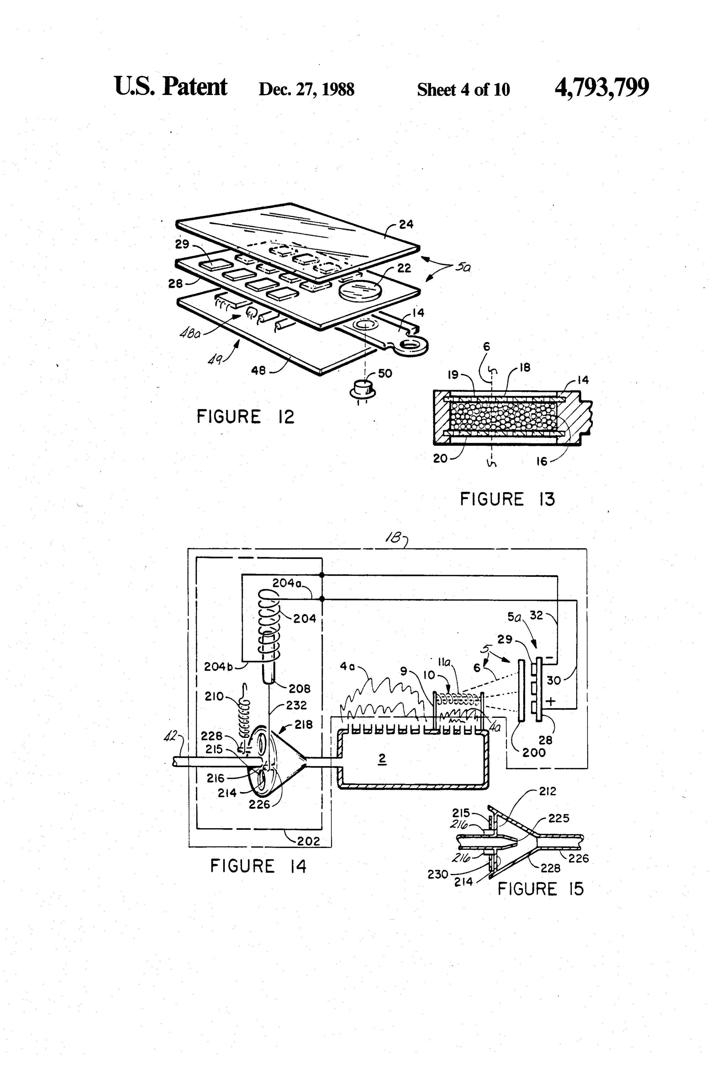
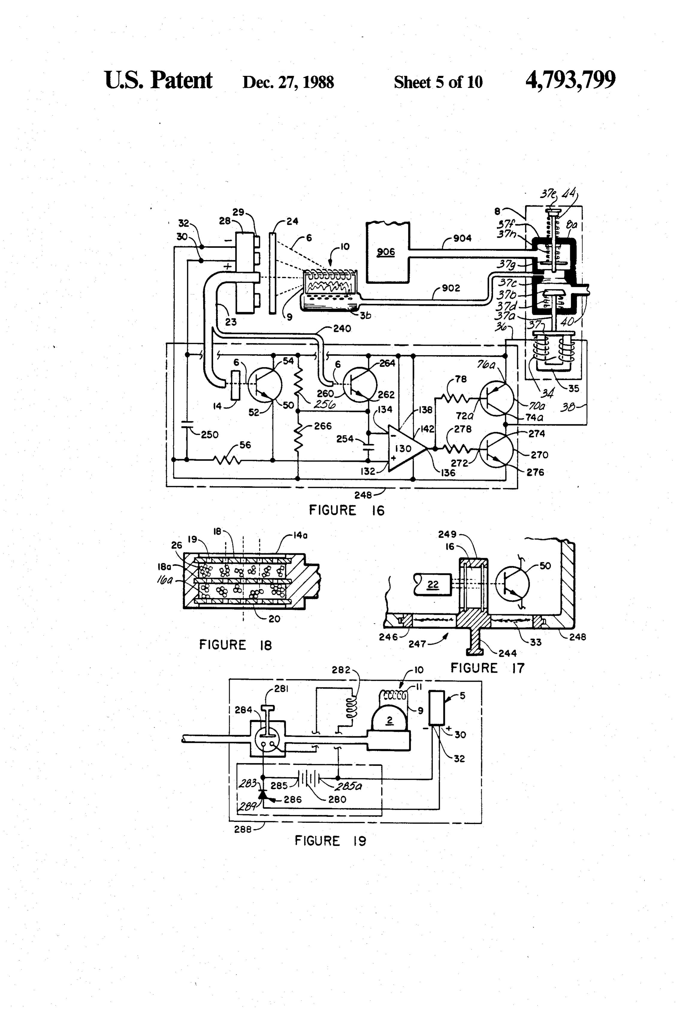
ter for emitting in the 675 nm or 890 nm regions while FIG. 19 is a schematic diagram of an electronic igni another section of the emitter may be constructed of tion device for use with the combustion device of the lanthanide oxides or other chemicals that emit in other present invention;
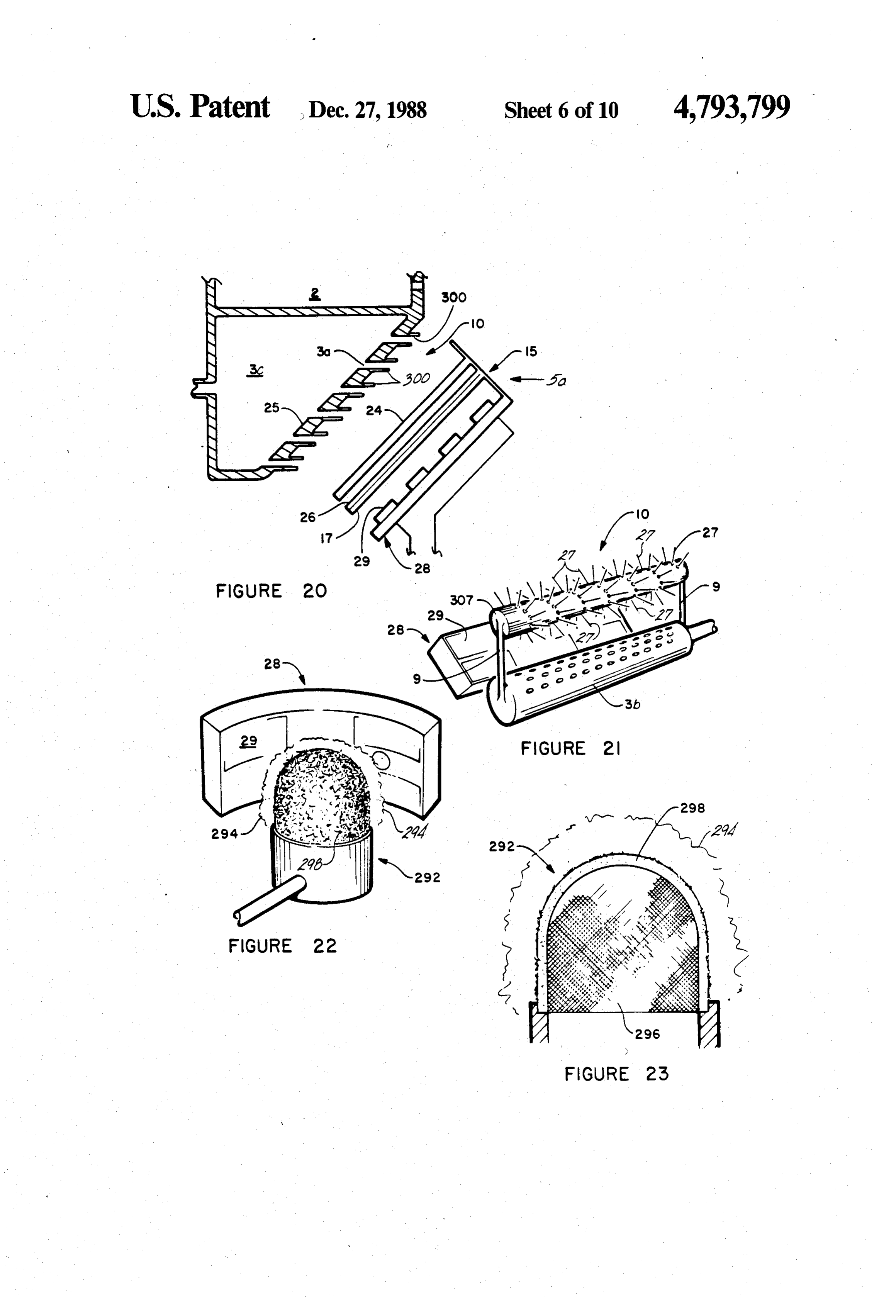
narrow regions of the spectrum. FIG. 20 is a schematic and partial side sectional view A quartz or silicon dioxide fiber or high concentra of a pilot burner with molded protruding fingers for tion silicon dioxide glass fiber or filament may be used producing characteristic wavelength electromagnetic as both an emissive means and light pipe filter to carry radiation;
large amounts of light of the appropriate wavelength to FIG. 21 is a schematic and perspective view of a the CO or other gas-sensitive means. The in-flame por ceramic fiber emissive element molded to a ceramic tion of this (high) silicon dioxide fiber may be coated 10 rod;
with thermally stimulated quantum emitters discussed FIG. 22 is a schematic and perspective diagram of a above. s porous ceramic surface burner and a curved photovol The apparatus can be used not only with gas appli taic sensor;
ances but also with liquid and solid fuel combustion 15 FIG. 23 is a schematic and side sectional view of a appliances. The apparatus may also be used as a conve burner similar to that of FIG. 22 showing a screen, a nient emitter of light of a known frequency, i.e., in porous ceramic wall and fibers;
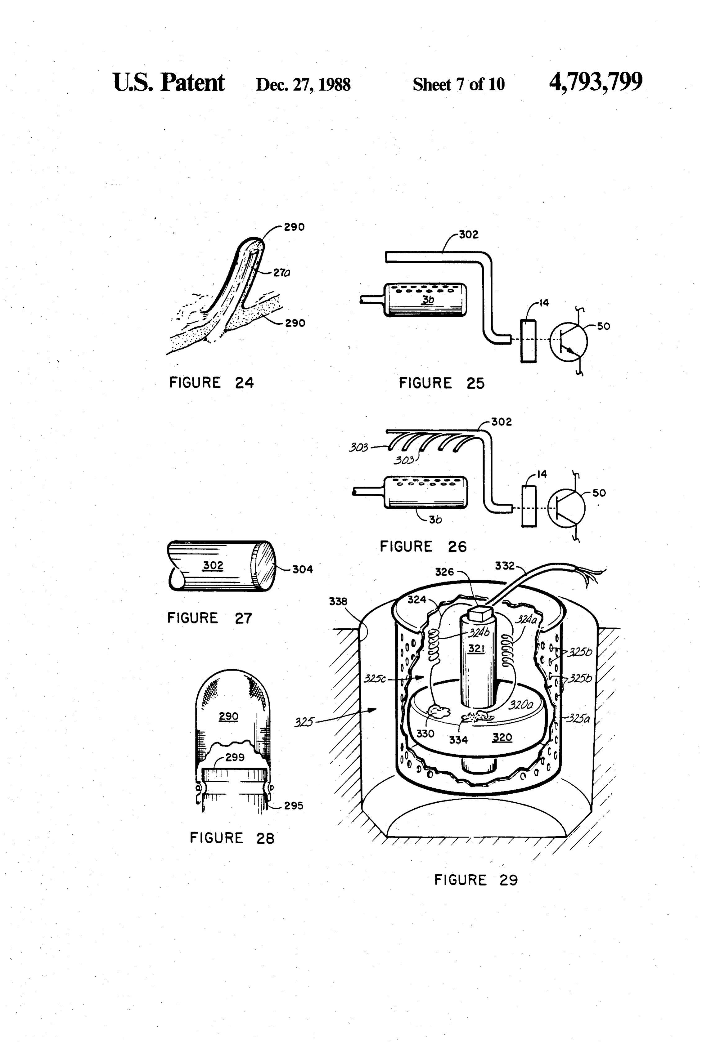
specific spectral regions, for camping, emergency use, FIG. 24 is a schematic and perspective view of a fiber and other viewing and spectroscopic detection pur for use in the device shown in FIG. 23; poses. FIG. 25 is a schematic and side elevation view of a 20 fiber optic emissive element;
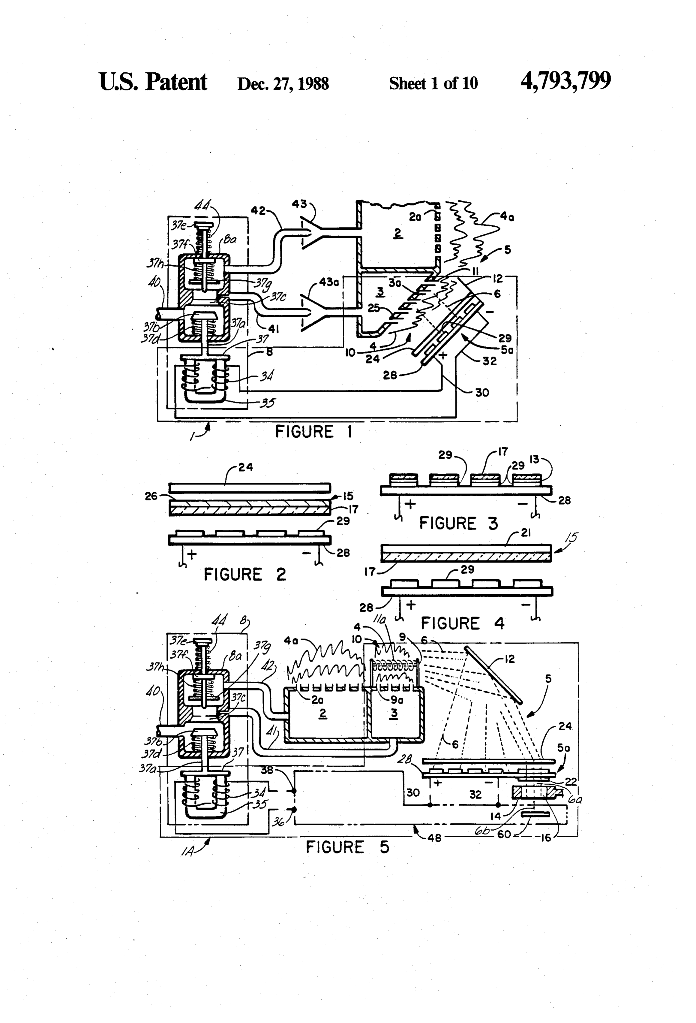
BRIEF DESCRIPTION OF THE DRAWINGS FIG. 26 is a schematic and side elevation view of the In the drawings: multiple-strand fiber optic emissive element alternative FIG. 1 is a schematic diagram of a combustion device to the fiber optic emissive element of FIG. 25; having a fuel flow control valve operated by a photo 25 FIG. 27 is a perspective view of a gas sensor coated voltaic sensor; on one end of a fiber optic emissive element; FIG. 2 is a schematic and side sectional view of a first FIG. 28 is a schematic and side sectional view of a alternative embodiment of the photovoltaic sensor of ceramic fiber-reinforced mantle in the form of a ther FIG. 1; mally stimulated quantum emissive element; FIG. 3 is a schematic and side sectional view of a 30 FIG. 29 shows a schematic perspective view of a second alternative embodiment of the photovoltaic cutaway portion of a combustible gas sensor for use in sensor of FIG., 1; combination with the combustion device of the present FIG. 4 is a schematic and side sectional view of a invention for sensing combustible gases which are third embodiment of the photovoltaic sensor of FIG. 1; heavierFIG.
than air;
30 is a schematic view showing the combustion
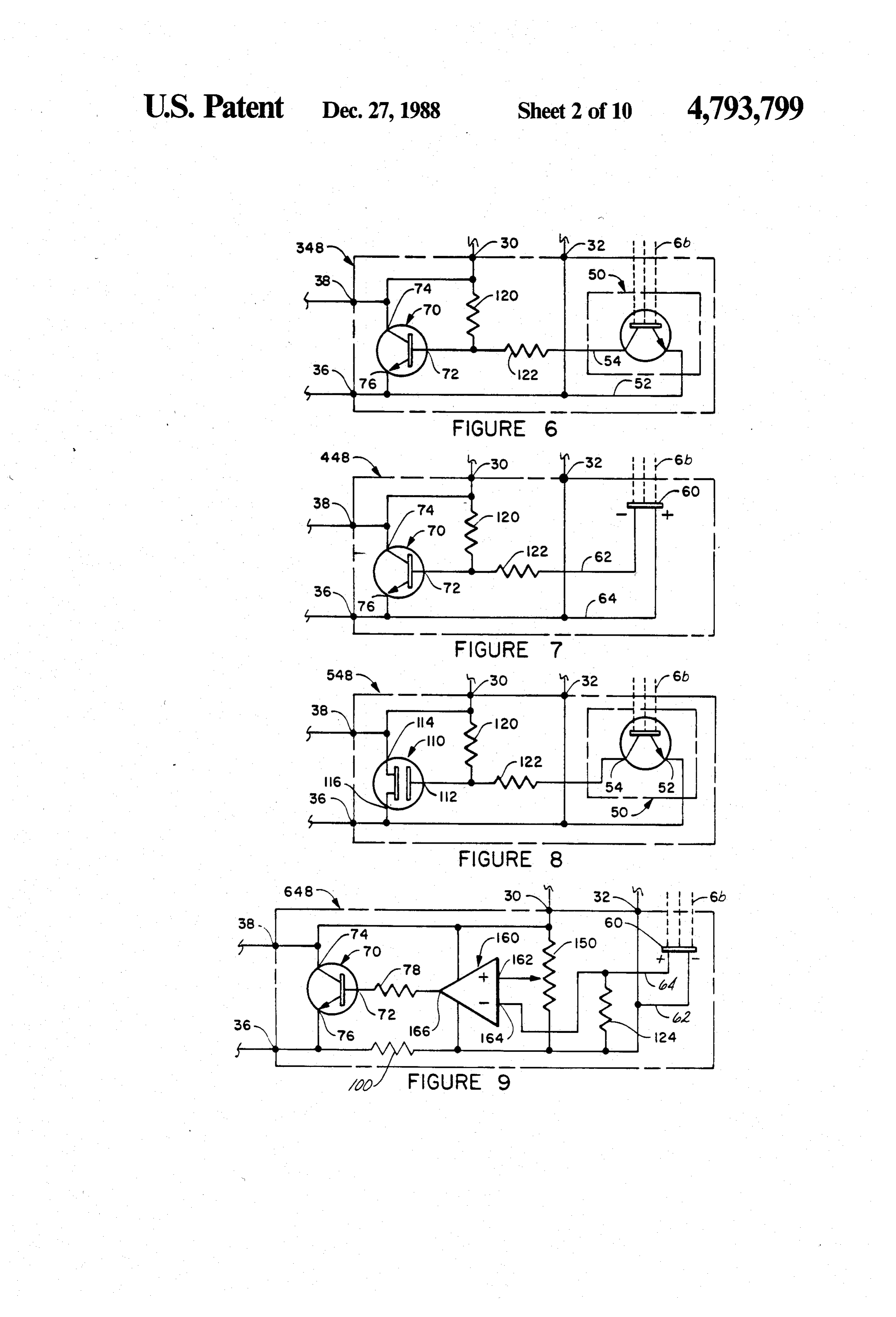
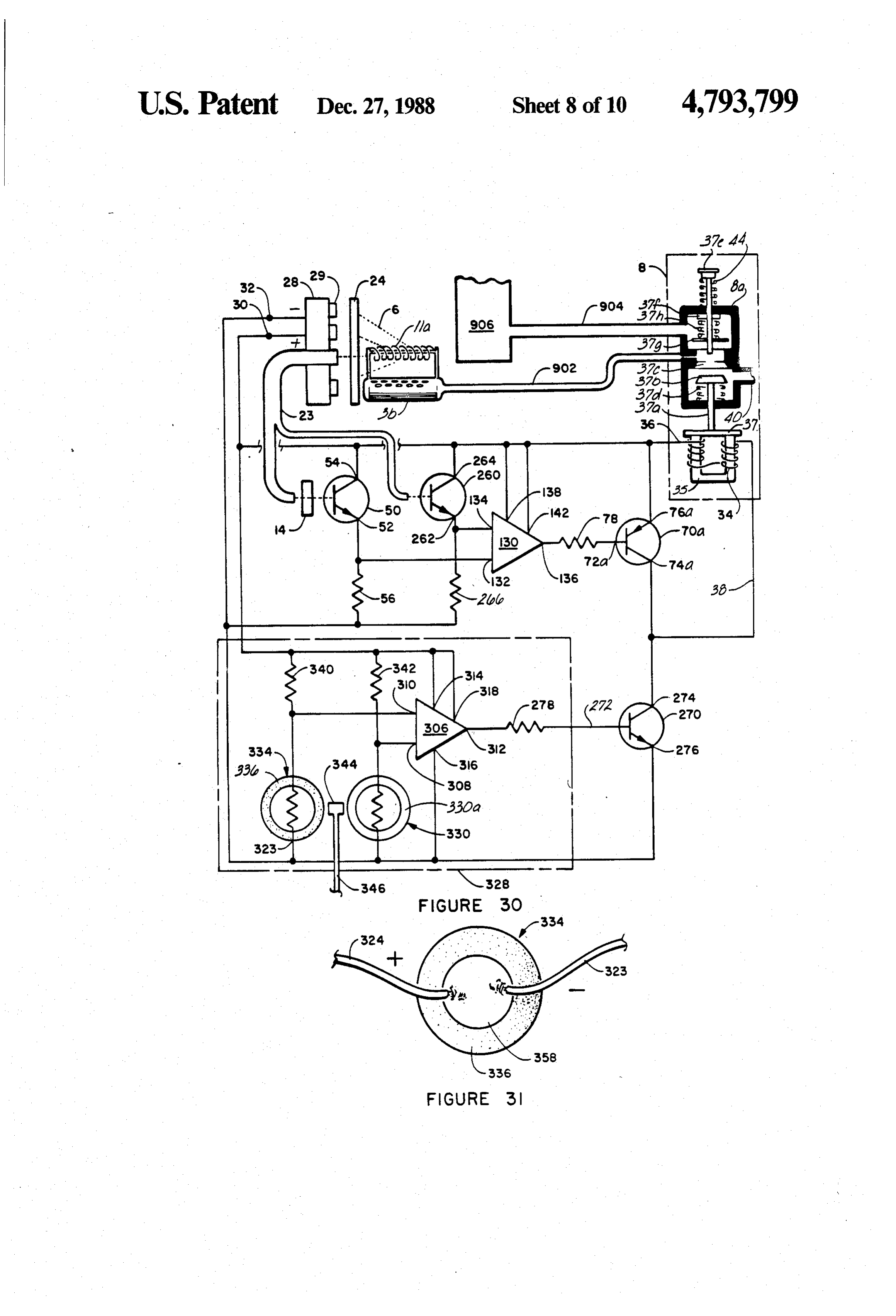
FIG. 5 is a schematic diagram of a second embodi 35 ment of a combustion device having a fuel flow control device of FIG. 16 in combination with an electronic circuit for controlling the fuel control in conjunction valve operated through an electronic circuit by a photo with the combustible gas sensor of FIG. 29; voltaic sensor and a combustion product sensor; FIG. 31 is a schematic view of a catalytic thermistor FIGS. 6-10 are schematic diagrams of embodiments of the circuit of FIG. 5 coupling the fuel valve and the for
use in the combustible gas sensors of FIGS. 29 and sensors;
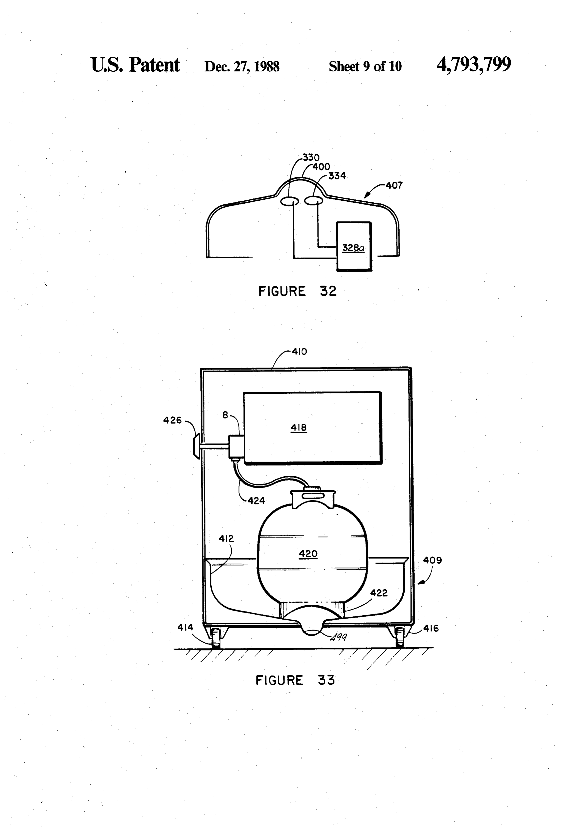
FIG. 32 is a schematic and side sectional view of a
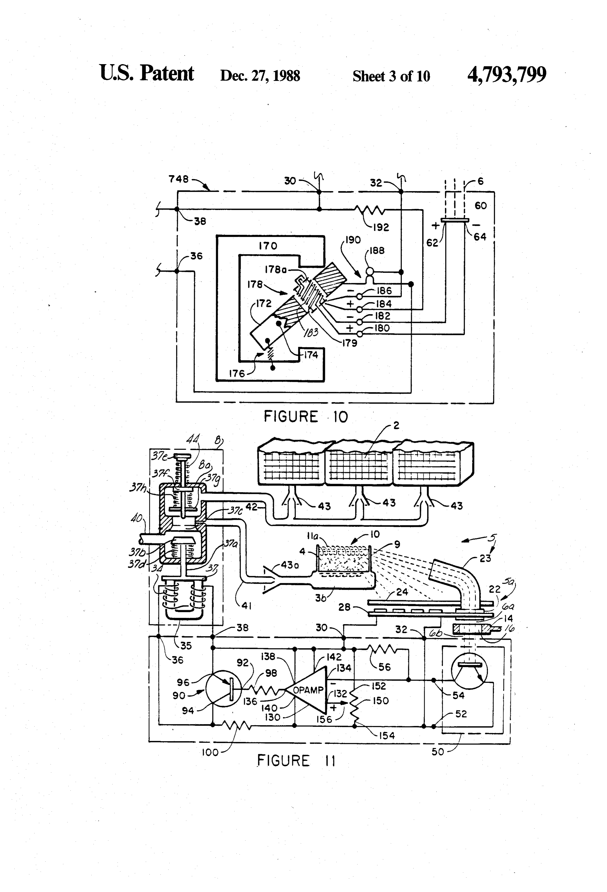
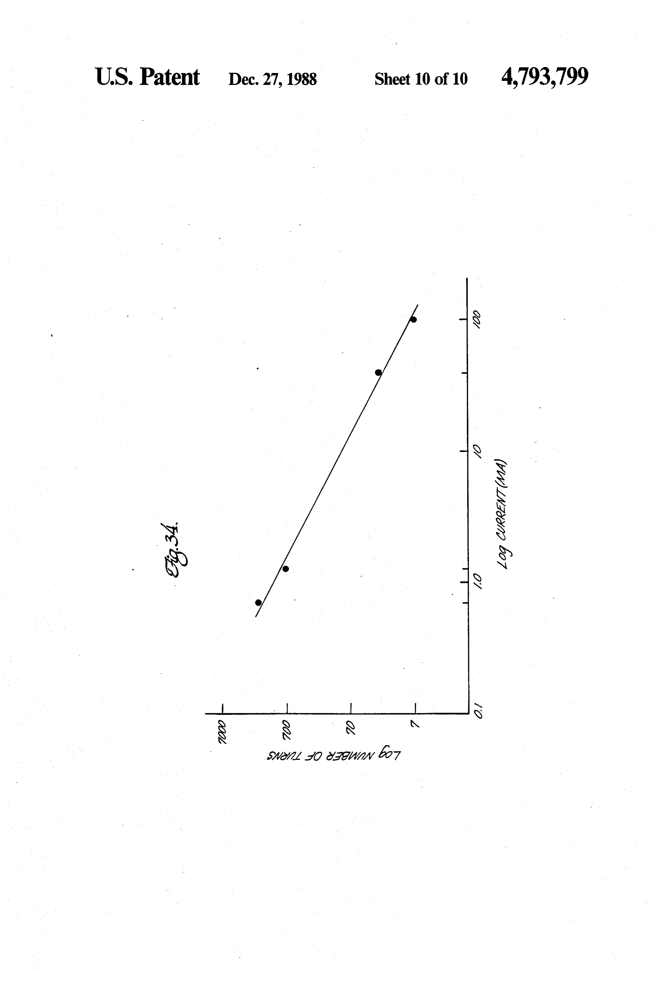
FIG. 11 is a schematic diagram of a third embodiment combustible gas sensor and indicator for use in detect of a combustion device including a fuel flow control ing combustible gases which are lighter than air; valve and photoelectric and combustion product sen FIG. 33 is a schematic and side sectional view of an sors in combination with a light guide; 45 unvented combustion device including a heavier-than FIG. 12 is a schematic and perspective view of a air sensor and control apparatus for use with a combustion usingcombustible the gas sensor and safety shutoff system combustible gas sensor of FIGS. 29-31; and device such as that shown in FIGS. 5 or 11; FIG. 34 is a graph of the relationship between the FIG. 13 is a schematic and side sectional view of a combustion product sensor and holder for use with a number of turns in and the current through a coil in the 50 fuel valve.
combustion device such as that shown in FIGS. 5 or 11;
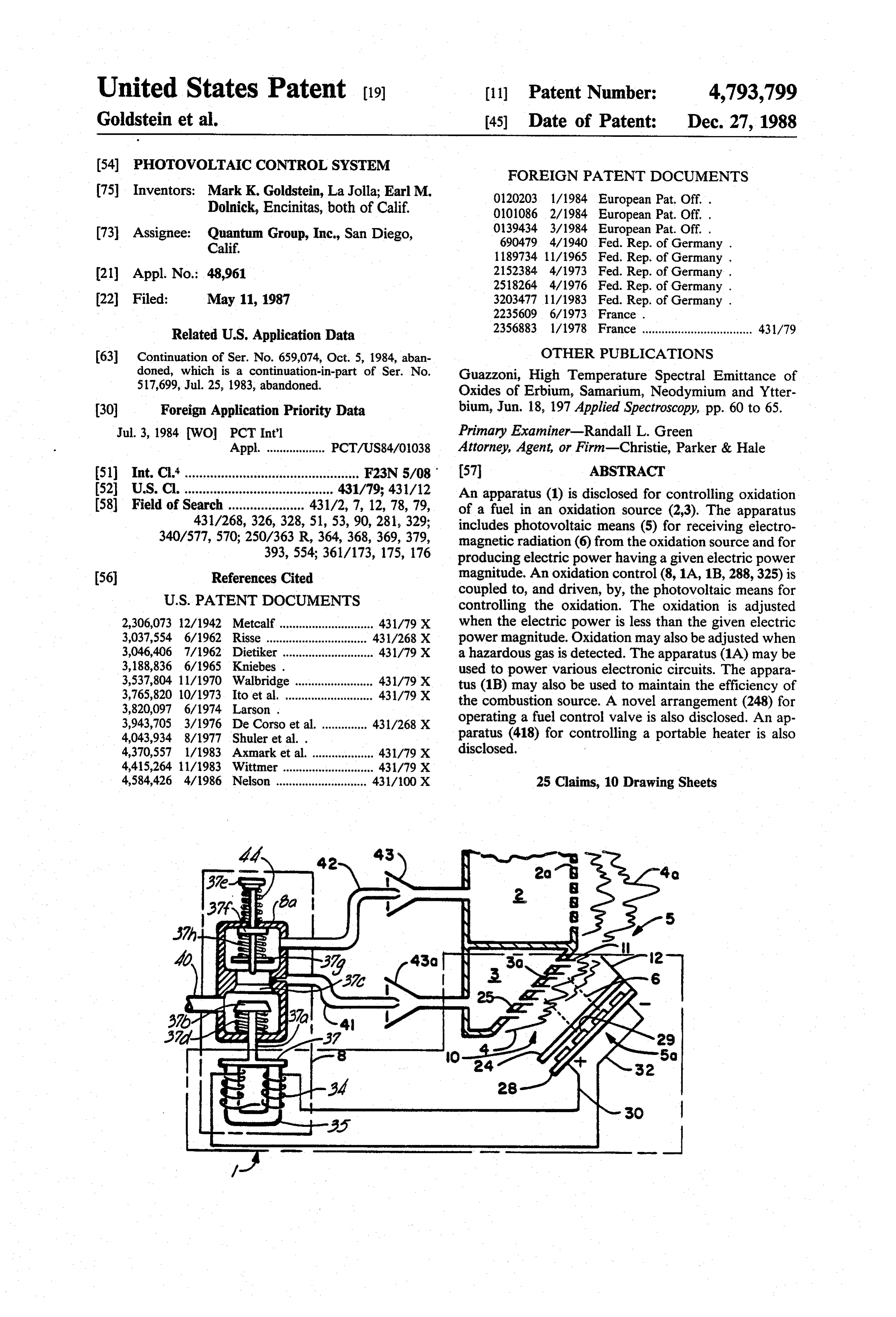
FIG. 14 is a schematic diagram of a combustion de MODES FOR CARRYING OUT THE vice including means for adjusting the air-fuel mixture; INVENTION FIG. 15 is a side sectional view of a portion of the In FIG. 1, a photovoltaic safety control system 1 for apparatus of FIG. 14 for adjusting the air-fuel mixture; 55 controlling
FIG. 16 is a schematic diagram of a fourth embodi dation sourceoxidationincludes of a fuel or combustion of an oxi a photovoltaic control system 5.
ment of a combustion device including a fuel flow con The photovoltaic control trol valve, a photoelectric and combustion product taic means 5a for receiving system 5 includes photovol electromagnetic radiation, in sensors in combination with light guides and an electric the form of infrared, ultraviolet, or visible radiation 6 circuit for controlling the fuel valve; from the oxidation source in the form of main burner 2 FIG. 17 is a schematic add partial side sectional view and pilot burner 3. The photovoltaic means Sa is of a combined sensor/getter cell for isolating the com adapted for producing electric power having a prede bustion product sensor from undesirable particles and termined electric power magnitude (not shown). from interfering gases; The photovoltaic safety control system 1 also in FIG. 18 is a schematic and side elevation view of a cludes a fuel control in the form of magnetically latched section of a gas sensor and holder showing sensors for valve 8 coupled to, and driven by, the photovoltaic sensing different gases similar to the combustion prod means 5a for regulating the combustion in the form of uct sensor and holder of FIG. 13; flames 4 and 4a in the pilot burner 3 and the main burner
Page 15
2, respectively. Tee safety control system 1 is adapted ture, function and operation of the butterfly valve 37g is such that the combustion is terminated when the elec well known in the art.
tric power is less than the predetermined electric power The pole piece 35 and shutoff coil 34 are similar in magnitude. design to those found in systems with thermocouple and It will be understood that the description herein in thermopile controls, but have many more turns (not cludes a description of the method for utilizing the shown) to allow use with lower currents and higher apparatus described. voltages produced by photovoltaic means. Referring to the schematic of FIG. 1 in more detail, a When combustion of an air-fuel mixture from cham combustion apparatus is provided comprising the pho bers 43 and 43a occurs at burners 2 and 3, flame 4 and tovoltaic safety control system 1, main burner 2, and 10 4a is produced and electromagnetic radiation 6 is pro latched valve 8. The main burner 2 produces flame 4a duced by the heat of combustion. In the preferred form, through ports 2a for producing heat, flame, or light. the photovoltaic means 5a is so placed as to be irradi Main burmer 2 is provided with fuel (not shown) ated by radiation 6 from the pilot burner 3, but any through pipe 42 and through means for combining the configuration with respect to burners 2 and 3 suitable fuel with oxygen-containing gas and for regulating a 15 for controlling the combustion source is contemplated. gas-fuel mixture in the form of air-fuel mix chamber 43 Various arrangements are described herein. for combustion. The pilot burner 3 in the control system The photovoltaic means 5a includes a photovoltaic 1 is similarly provided with ports 3a for producing array 28 of one or more individual photovoltaic cells 29. flame 4 for providing a standard flame or light. The 20 The individual photovoltaic cells 29 are coupled in pilot burner 3 is provided with fuel through a pipe 41 series for producing potential and current for output and pilot air-fuel mix chamber 43a. from the photovoltaic array for controlling the shutoff The magnetically latched valve 8 is provided for coil 34. In an alternative form, the individual photovol regulating the supply of fuel to the air-fuel mix cham taic cells 29 may be coupled in parallel or in a combina bers and for regulating combustion. Valve 8 may in 25 tion of series connections and parallel connections in clude any magnetically or electrically controllable con order to produce appropriate potential and current for trol mechanism presently known that employs a mag voltaic arraythe28shutoff controlling coil 34. The output of the photo netic safety latch mechanism, adapted for use with the positive conductoris30coupled to the coil 34 through a apparatus after suitable modification to the coil wind positive and negative conductors areconductor
coupled to the ings. Because of the increased voltage (potential) avail 30 shutoff coil 34 in order to maintain the valve 8 for pro able through use of the photovoltaic means 5a, a variety viding fuel to the mix chambers during normal opera of new valves may be designed and constructed using a tion as discussed above. The individual photovoltaic variety of electronic components. Preferably, the valve cells 29 are arranged and coupled in the array 28 as is is held open when the apparatus is operating normally, and automatically closes in response to a restoring 35 well known in the art, as are conductors 30 and 32 and their couplings. The array 28 is preferably oriented with force, such as spring pressure when an abnormality in respect to the flame 4 of pilot burner 3 such that the the operation of the combustion device occurs
The latched valve 8 preferably further includes a individual photovoltaic cells 29 are irradiated by radia fixed horseshoe pole piece 35, which during normal with respectpilot tion from
burner 3. The minimum requirement location of the array 28 is that sufficient operation, holds the top pole piece 37 in the valve body radiation must strike the individual 8a such that the flow channel between pipe 40 and pipes to produce the require current and photovoltaic potential at cells 29 conduc 4 and 42 is maintained and the valve 8 is in an open tors 30 and 32 for controlling the magnetically latched position, as shown in FIG. 1. The fixed horseshoe pole valve 8. As will be described in more detail below, it piece includes shutoff coil 34, which produces a mag may be desirable to drive other components with the netic field. The characteristics of the coil are described 45 in more detail with respect to FIG. 30. The windings of potential and current produced by the array 28. A cover of transparent material, such as glass 24, may be pro coil 34 are such that the top pole piece 37 is preferably vided over the individual photovoltaic cells 29, between held against the fixed horseshoe pole piece 35 when a potential and current developed in the photovoltaic cells 29 and the pilot burner 3, for preventing overheat ing of the photovoltaic array.
means Sa is applied to coil 34 for holding valve 8 open. 50 The array 28 comprising the individual photovoltaic The valve 8 is generally constructed so that the flow of cells 29 is preferably composed of any well known fuel through pipe 40 to the main burner 2 cannot con photovoltaic material, such as amorphous thin film, tinue unless the magnetic latch or top pole piece is main single crystal, or polycrystalline silicon, cadmium tellu tained at the horseshoe pole piece 35 by the power ride, mercury cadmium telluride, indium cadmium arse produced from the photovoltaic means 5a. 55 nide or copper indium diselenide. Alternatively, a lay Valve 8 is provided with a top pole piece 37 compris ered semiconductor can be used, for example silicon ing a first stem 37a coupled to the top pole piece 37. The and indium gallium arsenide or silicon and indium first stem 37a is journaled through a valve body 8a and diselenide For example, a silicon photovoltaic cell will terminates in a valve tip 37b. The valve tip 37b is biased produce a current with a voltage of approximately 0.45 toward a valve seat 37c by a first spring 37d. Valve tip volts. This is sufficient to control the valve 8. Other 37b and valve seat 37c operate to prevent flow of fuel electronic circuits described below may be incorpo into the burners. Opposite the stem 37a and valve tip rated into the combustion device, e.g. an alarm. Most 37b is a typical prime button 37e biased away from the typical silicon semiconductor circuits require voltages valve body 8a through a second spring 44. The outward greater than 1 volt. Therefore, several photovoltaic motion of the prime button 37e is limited by stop 37 fon 65 cells are connected in series to obtain the proper operat the interior of the valve body. Interior to the stop 37 fis ing voltage for controlling valve 8. Additional photo a butterfly valve 37g biased inwardly away from the voltaic cells would be provided where other electronic side of the valve body by a third spring 37h. The struc circuits are incorporated into the combustion device.
Page 16
The number of series-connected photovoltaic cells re cooled emissive element does not significantly interfere quired to drive the various elements will depend on the with operation of the photovoltaic array except to the number of circuit element and the specifications of the extent background radiation heats the photovoltaic cell, combustion source. causing it to lose efficiency. The photovoltaic cells 29 preferably produce a po A benefit in using the thermally stimulated quantum tential and current upon irradiation by infrared, visible, emitters as the emissive element is that the radiation is or ultraviolet radiation 6, but cease to produce such emitted based on quantum changes in the orbital elec potential and current when the radiation ceases and trons. As a result, the effect of reducing the heat by when only longer wavelength radiation is incident on which the emissive element is heated reduces the inten the array 28. For example, if silicon photovoltaic cells 10 sity of the emissions, but not the characteristic wave are used, the response curve for such silicon cells peaks lengths thereof. The emissive element can then be se at about 900 nanometers and falls off rapidly at 1100 lected when narrow band wavelengths are desired so nanometers. Therefore, it is desirable to have radiation that the emission spectra occurs in the near infrared, 6 produced during normal combustion in the wave visible, or ultraviolet region and so that the peak wave length region of about 900 nanometers in an amount 15 length of the emitted light does not vary as a function of sufficient to control the control valve. The radiation is flame temperature caused by variations in fuel, fuel preferably below 1100 nanometers. Furthermore, a pressure, and other environmental factors. photovoltaic cell operating in the wavelength region In one preferred embodiment, the ports 3a of the pilot between 900-1100 nanometers would be relatively in burner 3 comprise the emissive element 11 embedded in sensitive to black body radiation from the surrounding 20 or attached to the material of the pilot burner and in elements in the combustion device, which is commonly another embodiment the emissive element 11 is integral of a longer wavelength. with the ports 3a (FIG. 20). The sensitivity of the photovoltaic cells is shown by Alternatively, radiation can be produced by the heat noting that the quantum band gap in solid state devices from catalytic oxidation (not shown) in which no flame has a defined and sharp threshold. The power output of 25 is present.
a photovoltaic cell falls off abruptly over time and not In operation, the combustion device of FIG. 1 is linearly or continuously as does a thermocouple, where started by holding the valve tip of latched valve 8 in an radiation in the optimum response region ceases. There open position through the adjacent end of the butterfly fore, when stimulation of the solid state device at the valve 37g against biasing valve spring 44, thereby allow characteristic wavelength is eliminated, the operation 30 ing the fuel, for example in the form of a gaseous hydro of the solid state device is changed abruptly. The band carbon, to enter through pipe 40. The fuel enters valve gap of the solid state device may be tailored by doping body 8a and flows through pipe 41 and into the pilot the device with selected impurities, known in the art to air-fuel mix chamber 43a. The air-fuel mixture then maximize the pertinent functional characteristic. With flows to pilot burner 3 and is ignited by an ignition the photovoltaic cells, for example, the device can be 35 system, such as a piezoelectric ignition (not shown) or modified to operate optimally in the near infrared spec the ignition system to be described below with respect trum. The band gap selected for the particular device to FIG. 19. The emissive element 11 is heated to incan thereby defines the response region for the particular descence or luminescence for producing radiation. If device. sufficient radiation is produced to provide a potential The photovoltaic control system 5 includes an emis and current in the photovoltaic array 28, the top pole sive element 11 placed in the combustion area in the piece 37 is held by magnet 35. The butterfly valve can flame 4 for emitting radiation of a characteristic wave then be set for producing flame 4a in the main burner. length. The emissive element 11 is heated to incandes The initial heating of the emissive element 11 is ac cence (for black body radiation) or luminescence (for complished over a short period of time, i.e., four sec thermally stimulated quantum radiation). Silicon diox 45 onds, to produce the infrared and visible radiation 6. ide is one example of an emissive element and produces The radiation is absorbed by the photovoltaic means 5a radiation having a characteristic wavelength near 900 in the form of the individual photovoltaic cells 29. A nanometers upon being heated by flame 4 when used in portion of the radiation is converted to electric potential conjunction with silicon photovoltaic cells. Holmium and current, or power, which is applied from the photo or erbium may be used as thermally stimulated quantum 50 voltaic means through conductors 30 and 32 to the emitters if a wavelength of around 675 nanometers is latched valve 8. The potential and current control the desired from the emissive means. Furthermore, the shutoff coil34 to maintain the latched valve 8 in an open emissive element is formed such that when flame 4 position during normal operation. In the usual manner, changes in such a way that a dangerous condition re the magnetic field attracts the top pole piece 37 against sults, such as in a flame failure, the emission of radiation 55 the opposing bias of first spring 37d to maintain the flow by the emissive means 11 of the characteristic wave of fuel through pipe 40. The pole piece 37 is maintained length changes very rapidly to indicate the flame adjacent the surface of horseshoe pole piece 35, thereby change. For example, the emissive element is preferably maintaining the valve in an open position as long as the formed of fine wire or refractory material which cools emissive means produces sufficient radiation at the rapidly upon flame failure, so that radiation only of 60 characteristic wavelength.
wavelengths longer than 1100 nanometers is emitted by If the flame 4 were to be extinguished for any reason, the emissive element and received by the photovoltaic or if the flame were to lift off ports 3a due to insuffi means. In such a case, the longer wavelength radiation ciency of oxygen, the emissive element would quickly is not converted by the photocell because the energy of cool and the wavelength of radiation produced by the the incident photon is less than that for which the pho 65 emissive element 11 would increase. Since the photo tocell produces a potential and current. Therefore, voltaic means Sa would be relatively insensitive to background radiation from the surrounding furnace longer wavelengths, as described above, the potential structure and longer wavelength radiation from the and current output from the photovoltaic array would
Page 17
drop rapidly. As a result, the potential and current pro and visible region produced by the emissive element vided through conductors 30 and 32 would decrease, when the CO concentration is low. However, the thereby causing a reduction in the electromagnetic field Shuler chemical compound, in the presence of CO, such that the top pole piece 37 leaves the surface of the undergoes a change altering the ability to absorb and horseshoe pole piece 35. The bias of first spring 37d reflect light in the infrared and visible region. With would then force the valve tip 37b upward, as viewed in increasing CO concentrations, the amount of absorbed FIG. 1, thereby closing latched valve 8. and reflected radiation in this region increases so that The above-described device can detect, among other the intensity of radiation at the array 28 decreases. The things, loss of flame and incorrect air-fuel mixture caus change in quantity of light absorbed by the substance is ing flame lift-off, and can provide means for shutting off 10 proportional to the concentration of carbon monoxide the supply of fuel in a relatively short time when such present and can be used to calibrate the regulation of the incomplete combustion occurs. The system is self-pow fuel control to shut off the combustion device when ered and fail-safe in that the system operates only when hazardous concentrations of CO are present. Other there is the required combustion. No external power steps may be taken such as closing the main fuel valve sources are required since the photovoltaic cells and the 15 for the house or other building. The Shuler chemical coil 34 can be adapted for producing the potential and compound is also beneficial because it can be regener current required to operate the magnetically latched ated.
valve 8. Furthermore, the photovoltaic cells can be Carbon monoxide is ordinarily a by-product of com further adapted to operate additional electronics as bustion. In many situations CO is produced in danger described below. Because the system will automatically 20 ous amounts, e.g., when the amount of oxygen being shut off when the radiation of the characteristic wave mixed with the fuel at the mix chambers 43 and 43a is length is interrupted or its intensity is reduced, the decreased, the burner is dirty, or the flame temperature above-described device can be adapted or calibrated to is reduced. The CO-sensitive coating, which is normally terminate combustion at any time when the transmission transparent to light in the infrared and visible region, of infrared, ultraviolet or visible radiation 6 is inter 25 absorbs carbon monoxide and absorbs and/or reflects rupted. the incident radiation of wavelength in the infrared and The reflector 12 may be provided adjacent the photo visible region. The potential and current produced at voltaic means 5a for reflecting or focusing any scattered the array 28 of photovoltaic cells concurrently drops characteristic wavelength radiation toward the photo off significantly, thereby closing latched valve 8 as voltaic array. The reflector 12 may consist of a con 30 described above. As a result, the photovoltaic control verging or parabolic mirror (not shown) to collect and system 5 has a response time for reacting to the presence focus the characteristic wavelength radiation. Alter of carbon monoxide or other selected target gases nately, a lens (not shown) may be used. which is comparable to the response time of the photo In one form of the invention there is provided a plate voltaic means. 5a without the CO-sensitive material 15 between the emissive means 11 and the photovoltaic 35 when reacting to otherwise faulty combustion. Even cell array 28 comprising means 17 sensitive to a first when the emissive element ill continues to produce target gas in the form of toxic gases, such as carbon infrared radiation, the level of carbon monoxide due to monoxide or acid gases. Means sensitive to combustible incomplete combustion or other reasons serves to elimi gases such as propane or other gases, such as any non nate the infrared and visible radiation incident on the toxic volatile products placed in the fuel for detecting photovoltaic means 5a, thereby quickly cutting off the leaks, can also be used for the same purpose. The gas power to latched valve 8.
sensitive means may be a thin film coated onto any In another embodiment, the transparent plate 15 may transparent material, such as glass, quartz, or plastic further comprise means 26 sensitive to a second target windows or filters. The gas-sensitive means 17 is gas. The sensing means 26 may be a thin film of target adapted for preventing receipt of the electromagnetic 45 gas-sensing material coated on one portion of the plate radiation 6 by the photovoltaic means 5a when the 15 so that the second target gas-sensitive means is lo presence of the target gas reaches a given level. Specifi cated serially with respect to the CO-sensitive material cally, FIG. 2 shows a transparent plate 15 which is in the path of radiation 6. The second layer operates in stained, coated, or impregnated with the gas-sensitive the same manner as the gas-sensitive means 17 for con means 17, for example, a CO-sensitive material. The 50 trolling the latched valve 8. The second layer would transparent plate 15 is placed over the individual photo absorb sufficient radiation from the emissive means 11 voltaic cells 29 so that the gas-sensitive means is inter at the appropriate wavelength upon exposure of the posed between the photovoltaic cells 29 and the emis second layer to the specific target gas for which the sive means. In the preferred form, the transparent plate second layer is sensitive to inhibit transmission of the 15 is placed between the array 28 and the cover glass 24 55 radiation to the photovoltaic array 28. For example, the for keeping the gas-sensitive means from heating up. In second layer may be means for sensing acid gases, such one embodiment, the transparent plate 15 is silica as hydrogen cyanide, hydrogen chloride, and nitrogen coated fotoform glass, a material which may contain up oxides, convertible to a nitrogen acid, and other gases to 50,000 holes per square inch. The gas-sensitive means which are convertible to strong acids. Other gases 17 can be replaced relatively easily without having to which may be sensed include gases such as hydrofluoric replace the photovoltaic array 28 and the cover glass 24 acid and the other hydrogen chlorine gases. when the gas-sensitive means 17 is in the transparent The acid gas-sensing material may be any material plate 15. which changes its optical properties in the presence of An example of a CO sensor is that described in Shuler an acid gas. See, for example, Guenther, U.S. Pat. No. et al., U.S. Pat. No. 4,043,934. For present purposes, the 65 3,754,867. The acid gas-sensing material is partially radiation produced by the emissive means is in the infra transparent to the light 6 of the particular wavelength red and visible region. The Shuler chemical compound emitted by the emissive means 11 when no acid gases is ordinarily transparent to radiation in the near infrared are present. However, the sensor material inhibits, by
Page 18
absorption, reflection, or otherwise, the transmission of tion to those of FIG. 1 are numbered identically there light in a particular wavelength region of the spectra with. The air-fuel mix chambers 43 and 43a are omitted when one of the acid gases are present. Preferably, the for clarity, but are assumed to be present in a combus sensor material absorbs light 6 most strongly at those tion device.
wavelengths produced by the emissive means 11. The The photovoltaic safety control system 1A includes presence of more than one acid gas at any one time is emissive means 10 having an emissive element 11a in the cumulative so that the presence of two acid gases, each form of a radiant coil supported by a radiant coil holder at half the concentration of one required to close the 9. The radiant coil holder 9 supports the emissive ele valve, leads to the same inhibition of light transmission. ment 11a in the flame 4 of the pilot burner 3. The emis The effect of the presence of an acid gas will also be 10 sive element 11a produces infrared and visible radiation cumulative with the effects of CO. 6, which is reflected off of the reflector 12 to the photo The acid gas-sensing material includes a substrate, in voltaic means 5a, The reflector 12 and the photovoltaic the form of silica gel, alumina, or other substance chem means Sa are arranged with respect to each other and ically inert under the conditions of operation. The acid with respect to the burners 2 and 3 to provide adequate gas-sensing material is preferably a dye, such as methyl 15 irradiation of the photovoltaic means 5a for producing purple or methyl violet, which absorbs light in the red power. The various emissive elements 11a will be de or near infrared region in the presence of strong acids. scribed in more detail below.
A more specific dye may be used in conjunction with The photovoltaic safety control system 1A of FIG. 5 the thermally stimulated quantum emitter emitting any provides the photovoltaic array 28 in parallel with a where in the infrared, ultraviolet, or visible spectra. The 20 target gas-sensitive material 16, for example, CO-sensi dye absorbs a significant portion of the light 6 from the tive material, for independently controlling the latched emissive element 11 when the acid is present above a valve 8. The photovoltaic means 5a may include a filter predetermined dose. A buffer may be used to prevent 22 and/or 24 for restricting transmission of long wave indications due to ubiquitous sulfur dioxide and to as length light which causes heating of the photovoltaic sure reversibility of the color change. Alternatively, 25 array 28, to be described below, causing a reduction in some substrates which rapidly desorb and adsorb acid the efficiency thereof. Filter 22 (optional) transmits gas depending on the concentration in the air may be radiation in the ear infrared and red visible radiation used without a buffer. spectra from the emissive means 10 to enhance that The CO-sensitive material and the acid gas-sensing spectral region. It also prevents the target gas-sensitive material can also be located in a parallel relationship 30 material from heating up.
with respect to each other, rather than serially. For The filter 22 is placed below the cover glass filter 24 example, a CO-sensor can be placed over one portion of opposite the infrared reflector 12. The filtered radiation the photovoltaic array and an acid gas sensor can be 6a is then made incident on a target gas-sensitive mate placed over another portion. Alternatively, several rial 16 retained in a holder 14, to be described further arrays of photovoltaic cells may be provided, each with 35 with respect to FIG. 13. The sensitive material 16 is a corresponding target gas-sensitive means. similar to the sensitive material described above with In FIG. 3, there is shown a further embodiment using respect to FIGS. 2-4. In the case of the CO-sensitive a target gas-sensitive material such as the CO-sensitive material, when the level of carbon monoxide is rela material between the emissive pilot burner and the indi tively low, the CO-sensitive material transmits a portion vidual photovoltaic cells 29. The individual photovol of the incident radiation to means for sensing transmit taic cells 29 may be in the form of rectangular parallel ted light in the form of a light detector 60 for control epiped blocks to be placed in an array for forming the ling the fuel supply as a function of the concentration of photovoltaic cell array 28. A passive material such as a carbon monoxide.
silica coating 13 is applied directly to the individual The light detector 60 is adapted to be sensitive to the photovoltaic cells 29. The CO-sensitive material 17, 45 radiation being transmitted by filter 22 and by sensitive separately or in combination with other target gas-sensi material 16. The light detector 60 is electrically coupled tive materials, is then coated directly onto the thin silica in an electrical or electromechanical circuit 48 for con layer 13. The substrate may also be fused silica, etched trolling the fuel control valve. The positive and nega fused silica, quartz, etched quartz or high silica glass. tive conductors 30 and 32, respectively, of the photo The cover glass 24 may be placed as usual. This particu 50 voltaic cell array 28 are also electrically coupled to the lar arrangement is low in cost and compact in size. The control circuit 48 for independently controlling the operation of the particular embodiment of the photovol latched valve 8. Output leads 36 and 38 of control cir taic cell array 28 is similar to that described with respect cuit 48 are coupled to the shutoff coil 34. to FGS. 1 and 2. During operation, fuel is supplied through pipe 40 to A further embodiment similar to those of FIGS. 2 and 55 the burner 3. The flame 4 heats the emissive element 11 3 is shown in FIG. 4. There is provided a fused silica or to incandescence or luminescence. The radiation 6 is quartz cover 21 disposed over the photovoltaic cells 29, reflected by reflector 12 to the photovoltaic means 5a. between the photovoltaic cell array 28 and the flame 4. The radiation is transmitted through cover glass 24 to The lower side of the cover 21 is etched and coated the individual photovoltaic cells 29 and to filter 22. The with one or more of the target gas-sensitive materials, required potential and current for operating the mag for example, a CO-sensitive material. The function and netically latched valve 8 are provided through positive operation of the embodiment of FIG. 4 is similar to that and negative conductors 30 and 32 of the photovoltaic described with respect to FIGS. 2 and 3. array 28. Filter 22 transmits the selected band of light to In FIG. 5, there is shown a second embodiment of a the sensitive material 16, which transmits the filtered photovoltaic control system 5. The combustion appara radiation to the light detector 60. The light detector 60 tus of FIG. 5 is similar instructure, function, and opera is coupled to the shutoff circuit 48 for maintaining the tion to that shown in FIG. 1 except as noted below. magnetically latched valve in an open position. The Elements with identical structure, function, and opera potential and current produced in the photovoltaic
Page 19
array 28 provides power to the shutoff circuit 48 which lector-emitter circuit of transistor 70 to the negative in turn provides power to the coil 34. When the flame 4 conductor 32, and the valve closes since the current and is extinguished or burned in an inefficient manner, the potential in the shutoff coil 34 has decreased. The fuel photovoltaic array output decreases to a point where supply is thereby shut off to the burner. As discussed the magnetically latched valve closes, as described with respect to the apparatus of FIG. 1, if there is insuf above. In the case where the radiation emitted from the ficient light irradiating the photovoltaic array, the mag emissive means 10 falls outside the infrared and visible netically latched valve 8 will have insufficient potential range of the filter 24, for example, due to inefficient and current applied to hold the valve open against the burning or flame failure, the light transmitted by filter bias of spring 44. This also applies to the circuits to be 24 decreases to a point where shutoff circuit 48 shuts off O discussed below with respect to FIGS. 7-10. current and potential from the shutoff coil 34, thereby FIG. 7 shows a shutoff circuit 448 similar to that in closing magnetically latched valve 8. In the case where FIG. 6, except for the substitution of a photovoltaic cell the concentration of a target gas increases to dangerous 60 for the phototransistor 50. The negative output 62 of levels, the filtered light transmitted by filter 22 is ab the photovoltaic cell 60 is coupled to the first end of sorbed or reflected by the sensitive means 16, thereby 15 resistor 122 and the positive output 64 of photovoltaic decreasing the signal produced through light detector cell 60 is coupled to the negative conductor 32 of the 60. As a result, the output to leads 36 and 38 of the photovoltaic array 28. The balance of the circuit is shutoff coil 34 is decreased, in a manner to be described essentially the same as that discussed with respect to below, such that the shutoff coil 34 closes the magneti FIG. 6.
cally latched valve 8. 20 In operation, transmitted light from the sensing mate In FIGS. 6-10, several shutoff orgate control circuits rial 16 illuminates the photovoltaic cell 60 producing are shown for controlling combustion as a function of potential and current in outputs 62 and 64. When suffi hazardous gas (e.g., CO) dose exposure. The circuits cient radiation illuminates photovoltaic cell 60, the posi represent the control circuit 48 of FIG. 5. tive output through conductor 30 and resistor 120 is In F.G. 6, a shutoff circuit 348 is disclosed for short 25 drawn off of transistor 70 through resistor 122 to the circuiting the current to the coil, wherein the positive photovoltaic cell 60. Transistor 70 is thereby held in an and negative conductors 30 and 32 are coupled to the off state when sufficient radiation illuminates photovol shutoff circuit 348. Incident radiation from the filter 22, taic cell 60. When the incident radiation decreases or directly from the reflector 12 or emissive means 9, below a predetermined level determined by resistor 122, strikes an NPN phototransistor 50. The output termi 30 such current to the base 72 of transistor 60 from the nals 36 and 38 of the shutoff circuit 348 are electrically positive output 30 of photovoltaic array 28 is not drawn coupled to the the shutoff coil 34 as described above. off of transistor 70, and transistor 70 is thereby forced The positive conductor 30 is coupled to a first side of into conduction. The positive output of positive con a base current resistor 120 and also coupled to the col ductor 30 is thereby shunted through transistor 70 to the lector 74 of an NPN coil shorting transistor 70. The 35 negative output of negative conductor 32 of the photo second end of resistor 120 is coupled to the base 72 of voltaic array 28.
transistor 70. The negative conductor 32 of the array 28 In FIG. 8, there is shown an alternative shutoff cir is coupled to the negative lead 36 of the shutoff coil 34. cuit 548 similar to the shutoff circuit 348 of FIG. 6. Similarly, the emitter 76 of the transistor 70 is coupled However, there is substituted an N-channel field effect to the negative lead 36 of shutoff coil 34. The photo 40 transistor (FET) 110 for transistor 70. The positive transistor 50 provides current in its collector-emitter output 30 is coupled to the drain 114 of FET 110, and circuit wherein the collector 54 is coupled to a first end the negative lead 32 is coupled to the source 116 of FET of a resistor 22, the second end of which is coupled to 110. The remainder of the shutoff circuit 548 is similar the base 72 of transistor 70. The emitter of phototransis to that described with respect to FIG. 6. The operation tor 50 is coupled to the negative feed 36 of the shutoff 45 of the shutoff circuit 548 is similar to that of shutoff coil 34. circuit 348 except that, because gate 112 of FET 110 The operation of circuit 348 is as follows: When the draws no current, the controlling parameter of the shut valve is operating normally, light from the emissive off circuit 548 is the potential at gate 112 determined by element strikes the large photovoltaic array 28, generat the current drawn by phototransistor 50 through resis ing a current which flows through conductors 30, 32, 50 tors 120 and 122. When the incident radiation on photo 36, and 38 to coil 34. A potential then exists between the transistor 50 decreases, phototransistor 50 does not coil leads 36 and 38, which potential also appears across conduct, thereby increasing the potential at collector the collector 74 and emitter 76 of transistor 70. The 54. The potential at gate 112 therefore increases and transmitted light 6b striking the phototransistor 50 has FET 10 conducts.
already passed through the CO-sensing material 16 and 55 FIG. 9 shows a further embodiment of a shutoff cir through the associated optical components discussed cuit 648 utilizing a comparator circuit. The positive with respect to FIG. 5. Current flowing to the base 72 input 30 is coupled to one end of a potentiometer 150 of transistor 70 through resistor 120 causes transistor 70 and to the collector 74 of the NPN transistor 70. The to go into conduction. If sufficient light strikes transis negative conductor 32 is coupled to the negative lead 36 tor 50, the current through resistor 120 is drawn off 60 of the shutoff coil 34 through a current limiting resistor through resistor 122 in order to keep transistor 70 in the 100. Similarly, the emitter 76 of transistor 70 is coupled off state. However, if a target gas, for example, carbon to the negative lead 36 of the shutoff coil 34. The second monoxide, is present, the light striking phototransistor end of potentiometer 150 is coupled to the negative lead 59 is reduced. As a result, the current drawn off of the 36 of the shutoff coil 34. The wiper of potentiometer base 72 of transistor 70 is reduced, causing transistor 70 65 150 is coupled to the positive-sensing input 162 of a to go into conduction if the reduction is below a prede comparator 160. The output 166 of comparator 160 is termined level set by resistor 122. Current is then di coupled through base resistor 78 to the base 72 of tran verted from the positive conductor 30 through the col sistor 70. As with the shutoff circuit 448 of FIG. 7,
Page 20
transmitted radiation 6 irradiates photovoltaic cell 60, switch contact 188. The opposite contact of fixed whose positive output 64 is coupled to the negative switch contact 188 is movable switch contact 190 which sensing input 164 of comparator 160. The negative out is mechanically coupled to the end of armature 172 put 62 of photovoltaic cell 60 is coupled to the negative extending out of the interior portion of pole piece 70. output 32 of the photovoltaic array and to the negative 5 The movable switch contact 190 is coupled to the nega lead 36 of the shutoff coil 34. The negative output 60 tive lead 36 of the cutoff coil 34. The armature 172 is and the positive output 64 of the photovoltaic cell 60 held biased one way by the spring 176. The free end of are bridged by a load resistor 124. armature 172 presses against the movable switch ele The comparator discriminates the combustion prod ment 190, which together with fixed contact 188 pro uct concentration levels. Potentiometer 150 forms a 10 vides a conduction path for the current flowing be voltage divider for sampling the voltage across shutoff tween photovoltaic array 28 and the safety shutoff coil coil 34. The sample is applied to the positive-sensing 34.
input 162 of comparator 160. Load resistor 124 samples Under normal conditions, adjustable resistor 192 is the current produced by the photovoltaic sensor 60 adjusted so that the magnitude of the current in wind which sample is applied to the negative-sensing input ings 179 and 183 are equal. Since the currents flow in 164 of comparator 160. The potentiometer is adjusted opposite directions, there is no net magnetic field. If and the load resistor is chosen so that under normal carbon monoxide is present, the output of photovoltaic conditions of low levels of carbon monoxide, or other cell 60 will decrease as described above. The current in target gas, the voltage at the negative-sensing input 164 winding 179 will be therefore less than the current in is greater than the voltage at the positive-sensing input 20 winding 183 resulting in a net magnetic field being gen 162 of comparator 160. As a result, the output 166 of erated by the difference in current. The current flow is comparator 160 is held in the low state and, therefore, arranged so that magnetic field produced thereby is in the transistor 70 is nonconductive. Similarly, potential opposition to the magnetic field of the permanent mag and current is thereby placed across leads 36 and 38 of net. This results in a torque being applied to coil 178. shutoff coil 34. If carbon monoxide, or any other target 25 Because coil 18 is rigidly attached to armature 172, the gas, is present in a sufficiently high concentration for a latter being free to move about fulcrum point 174, the sufficient time, the light striking photovoltaic cell 60 armature 172 rotates about the fulcrum point in re decreases and the current output of photovoltaic cell sponse to the generated magnetic field. In so doing, the will likewise decrease. If the decrease is sufficient to outside end of armature 172 presses against the movable allow the potential at the negative-sensing input 164 to 30 switch element 190 causing it to break contact with the drop below that of the positive-sensing input 162 of stationary switch element 188. As a result, the circuit to comparator 160, the output 166 will enter the high state cutoff coil 134 is opened, causing magnetic latched which will send current through resistor 78 to base 72 of valve 8 to close.
transistor 70 causing transistor 70 to go into conduction. A third embodiment of the combustion apparatus and As a result, the potential and current applied across 35 photovoltaic control system is shown in FIG. 11. A fuel shutoff coil 34 is decreased and magnetically latched supply pipe 40 is shown for feeding fuel through a valve valve 8 is closed. body 8a. A magnetically latched valve 8 provides An additional embodiment of the cutoff circuit 48 is means for regulating the supply of gas to the combus shown in FIG. 10, with respect to cutoff circuit 748. tion apparatus. A pipe 41 transfers fuel from the valve The cutoff circuit 748 contains an electromechanical 40 8b to a pilot burner 3b through a pilot air-fuel mix cham switch for cutting off the potential and current to the ber 43a. A pipe 42 conveys fuel to a series of air-fuel mix cutoff coil 34. The cutoff circuit 748 is provided with a chambers 43 providing air-fuel mixture to main burners permanent magnet pole piece 170 shaped substantially 2.
as a "C". Between the open ends of the pole piece 170 Emissive means 10 for producing radiation of a char is placed an armature 172 having one end interior to the 45 acteristic wavelength includes an emissive element 11a pole piece 170 and coupled to the bottom thereof supported by a radiant coil holder 9. Other elements through an armature spring 176. The other end of arma common to the devices shown in FIGS. 1 and 5 are ture 172 extends upwardly, as seen in FIG. 10 and out given common reference numerals and have structures side of the interior portion of pole piece 170 and pivots and functions similar to those of the common elements about a mid portion of the armature 172 at an armature 50 of FIGS. 1 and 5. Other elements will now be described. fulcrum point 174. The armature 172 is provided with The radiation from the emissive means 10 falls on the bifilar wound coils 178 wound about a spool 178a. The cover glass 24 of the photovoltaic means 5a, The filter bifilar wound coil 178 consists of two windings, one 22 is provided in the photovoltaic means 5a as is a target winding 179 with connecting wires 180 and 182 and the gas-sensitive material 16 and holder 14, each having other winding 183 with connecting wires 184 and 186. 55 structures and functions comparable to similar elements The transmitted radiation 6 falls upon a photovoltaic in the above-described apparatus. Radiation is transmit cell 60 for producing potential and current at positive ted from the emissive means 10 through a fiber optic output 62 and negative output 64. The negative output bundle or single optical fiber 23 for transmitting only 64 is coupled to positive conductor 180 of a first wind the radiation from the emissive means 10 to the filter 22 ing 179 for the bifilar wound coils 178. The positive 60 (optional). The light transmitted through optical fiber output 62 is coupled to the negative conductor 182 of bundle 23, filter 22 and sensor material 16 is then made the first winding 179. The positive output 30 of the incident on a phototransistor 50, these elements being photovoltaic array 28 is coupled to the positive lead 38 similar to those as described with respect to FIGS. 5 of the cutoff coil 34 and through adjusting resistor 192 and 6. Phototransistor 50 may be a photo-darlington to the positive conductor 184 in the second winding 183 65 transistor. A shutoff circuit 848 regulates the fuel flow of the bifilar wound coils 178. The negative output 32 of to burners 2 and 3b by closing valve 8 when there is no the photovoltaic array 28 is coupled to the negative flame or when concentration of the target gas increases conductor 186 of the second winding 183 and to a fixed beyond a given level. As discussed below, the circuit
Page 21
may also be used to vary the air-fuel mixture as a func valve 8. A fraction of the radiation is converted to elec tion of burning efficiency. tric power of approximately 3 milliwatts, at 1.7 volts The positive output 30 of the photovoltaic array 28 is and a current of 1.8 milliamperes. Radiation 6 also illu coupled to the positive input lead 38 of the cutoff coil 34 minates the end of the optic fiber 23, which conducts and to the emitter 96 of a PNP transistor 90. The posi the light to the CO-sensitive material. If the CO-sensi tive output 30 is also coupled to one end 152 of potenti tive material is transparent, the radiation is transmitted ometer 150, to the positive power supply input 138 of to photo-darlington transistor 50.
operational amplifier 130 and also to the bias select input 142 of operational amplifier 130. Additionally, the willIn pass operation, light generated by emissive means 10 through optic fiber 23 and the CO-sensitive positive output 30 of the photovoltaic array 28 is cou 10 material held pled through load resistor 56 to the negative-sensing ton transistorin50.holder 14 and strike the photo-darling input 134 of operational amplifier 30. The wiper 156 of conduct current. Since the currentisofthereby The transistor the caused to
potentiometer 150 is coupled to the positive-sensing ton transistor is provided through resistor 56, the volt input 132 of operational amplifier 130. The other end age at the junction of resistor 56, collector 34 and the 154 of potentiometer 150 is coupled through resistor 100 15 to the negative input lead 36 of the cutoff coil 34. The negative-sensing input 134 of the operational amplifier output 136 of operational amplifier 130 is coupled so that the voltage at The 130 will be reduced.
potentiometer 150 is adjusted will be more positive than the through a base resistor 98 to the base 92 of PNP transis voltage at 134 if CO is not present. This ensures that the tor 90. The collector 94 of transistor 90 is coupled to the output at 136 will be in the high state, negative input lead36 of the cutoff coil 34. The negative 20 sistor 90 from conducting current. The preventing valve then tran oper output 32 of photovoltaic array 28 is coupled to the ates normally.
negative power supply input 140 of the operational amplifier 130 and to the negative input lead 36 of the material, If CO is present, as detected by the CO-sensitive cutoff coil 34 through resistor 100. the CO-sensitive material will darken, thereby The phototransistor 50 is included for conducting 25 reducing the amount of light striking phototransistor 50. current inversely proportional to the concentration of This reduces the current drawn by phototransistor 50 the target gas. The collector 54 of phototransistor 50 is from the positive output conductor 30 of the photovol coupled to the negative-sensing input 134 of operational taic array 28. As a result, the voltage at the negative amplifier 130. The emitter 52 is coupled to the second sensing input 134 rises. This occurs even though the end 154 of the potentiometer 150 and to the negative 30 extent of darkening is related to the time dependent input lead 36 of the cutoff coil 34 through resistor 100. concentration of carbon monoxide. The point at which The emissive element 11a may consist of a length of cutoffo the coil occurs can then be set for a value re Nichrome wire of thickness 0.005 to 0.010 inch wound lated to a human dose. If the CO concentration exceeds into a coil of about inch diameter and length of about 50 parts per million (ppm) for 4 hours, or 200 ppm for 4 inches. Placed about 2 inches below the emissive 35 thirty minutes or over 350 ppm for 10 minutes, the gas element is an array of silicon photovoltaic cells 28 con sensor 15 will darken sufficiently so that the voltage at sisting of six cells, each inch wide and 1 inches long the negative-sensing input 134 will exceed the value set and connected in series so that the total output voltage at the positive-sensing input 132. This will cause the is the sum of the voltages generated by the individual output 136 of operational amplifier 130 to enter the low cells. A portion of the radiation 6 produced by emissive state, thus drawing current through base resistor 98 means 10 strikes a target gas detection material 16 from the base 92 of transistor 90, causing transistor 90 to which is preferably in the form of carbon monoxide conduct. The conduction through transistor 90 diverts sensing material. The optic fiber 23 is 4 inches long and the current which formerly flowed through cutoff coil serves to allow the placement of the gas-sensing mate 34, thereby closing the valve.
rial in a region that is cooler relative to the pilot burner 45 FIG. 12 shows an arrangement for combining the 3. The optic fiber 23 may act to filter out the longer elements of the photovoltaic control system 5 into a wave infrared components of the radiation depending single photovoltaic control unit 49 for controlling com on its composition, i.e., glass, plastic, or silicon dioxide, bustion in a combustion device. The cutoff circuit 48a is thereby assisting in keeping the sensing material and its provided on a circuit board 48 to which is to be at holder cool and enhancing sensitivity. The operational 50 tached the phototransistor 50 and the holder 14 for the amplifier 130 may be a TLC 251 operational amplifier gas-sensing material. Oriented above the cutoff circuit by Texas Instruments, Inc. The principal requirement is 48 is the photovoltaic array 28 consisting of, for exam that the operational amplifier be able to function with ple, a 4X3 array of individual photovoltaic cells 29. The supply voltages as low as 1 volt. photoelectric array also includes, in a preferred embodi The photovoltaic control system of FIG. 11 may 55 ment, a filter 22 for filtering the radiation to be incident provide for the use of a fiber optic with one end in or on the phototransistor 50. The entire sensor apparatus is near the flame 4, for heating by the flame. The emissive covered by a cover glass 24. The location of the photo means, containing athermally stimulated quantum emit voltaic control system 5 relative to the combustion ter such as lanthanide oxides, is coated on the heated apparatus is dependent upon the means for transferring end for producing radiation of a characteristic wave 60 the radiation from the emissive means 10 to the control length. The fiber optic transmits the radiation to the system 5. Optical fibers may be used to couple the radia other end, which end has been etched and coated with tion from the emissive means 10 to the photovoltaic the CO-sensitive material for inhibiting transmission of array 28, enabling the photovoltaic system 5 to be radiation when carbon monoxide is present (see FIG. placed at a distance relative to the combustion device. 27). 65 However, if a direct light line must be maintained be If flame is present, the photovoltaic array 28 will tween the emissive means 10 and the photovoltaic array produce enough power from the radiation to operate 28, the control unit 49 must be placed closer to the both the CO detection circuit and the magnetic latched combustion source.
Page 22
FIG. 13 shows in detail the gas-sensitive material 16 of photocurrent produced is a sensitive function of and the holder 14 therefor. Radiation 6 is transmitted flame temperature. The resulting photocurrent and through sensitive material 16 when low concentrations potential produced by the photovoltaic array 28 may be of the particular gas to be sensed are present. Gas inlet used to control the amount of air flowing into the fuel holes 19 are provided in transparent windows 18 and 20 air mixture, thus optimizing the air-fuel ratio to maxi for admitting gas molecules to the sensitive material 16. mize the flame temperature. Since the emissive means The gas-sensitive material may be coated on silica gel may be made of materials with low thermal mass, such and placed in the holder 14. The silica gel sensor mate as 0.01-inch diameter Nichrome wire or smaller ceramic rial is not suitable for direct application to the surfaces filaments, the control system can respond very quickly of photovoltaic cells nor to plates such as plates 15 in O to temperature changes.
FIG. 2 because silica gel reduces the intensity of the The spectral filter 200 may be similar to the filters incident light through scattering and absorption unre described above with respect to FIGS. 5 and 11. The lated to absorption due to changing color of the sensor filter is employed to reduce heating of the photovoltaic material. Furthermore, silica gel particles are difficult to array 28 due to incident radiation and to aid in control evenly distribute over a large area such as that contem 15 ling the spectral response of the control, e.g., to aid in plated for the photovoltaic array 28. Additionally, small preventing too lean an air-fuel mixture. silica gel particles are difficult to bond without damag As discussed above with respect to the previously ing the chemical sensor property of the sensor material described control devices, fuel gas flows through inlet coated thereon. Silica gel is also easily dehydrated at pipe 40 to the gas-air proportioning valve 202. Fuel elevated temperatures and may be damaged. Therefore, passes through nozzle 225 and the resulting expansion the thin film coating described with respect to FIGS. causes air to be drawn in through the holes 214 and 215 2-4 is a preferred method for incorporating the gas-sen in the aperture plates. The gas-air mixture then flows sitive material in the photovoltaic control system 5 through pipe 42 to the burner 2 where it is ignited by which has some advantages over the method of FIG. conventional means (not shown). The emissive element 13. 25 11 placed within the flame 4 is heated to incandescence FIG. 14 shows an efficiency control system 1B for or luminescence. A portion of the resulting radiation controlling the air-fuel mixture delivered to the main may be directed (through various means as described burner2. The photovoltaic control system 5 is similar to above) through spectral filter 200. The filtered radiation those descried above with respect to FIGS. 1, 5, and 11, then strikes photovoltaic array 28 producing an electric except that the emissive means 10 is preferably located 30 potential and current. The photocurrent is conducted at the main burner 2 for producing radiation of the through conductors 30 and 32 to the coil 204 in the characteristic wavelength. Furthermore, the photovol proportioning valve 202. The movable armature 208 taic control system 5 includes a spectral filter 200 for moves in or out of the coil 204 depending on the change filtering out most of the radiation except that of the in current in conductors 30 and 32 with changes in the characteristic wavelength. Fuel is provided through 35 amount and wavelength of radiation produced in the pipe 42 into a gas-air proportioning valve 202 for mixing emissive element 10. The movement of the armature 208 the fuel and air. The proportioning valve includes an is transferred to the rotating aperture plate 230 through air-fuel mixing chamber 218 for mixing the fuel from post 226. The current flowing in coil 204 is so arranged pipe 42 with the air pulled in through air holes 215. The that the magnetic field thus produced exerts an attrac mixed air and fuel is then transported to main burner 2 tive force on armature 208 thereby pulling on post 226 for producing heat or flame 4a. A portion of the main for rotating the rotating aperture plate 230 in opposition burner includes the emissive means 10 comprising an to the biasing spring 210. As a result, the relative posi emissive element 11a supported by radiant coil holder 9. tions of apertures 215 and 214 can be varied, thereby Alternatively, the emissive element 11a may be incor varying the flow rate of incoming air. The combustion porated into the structure of burner 12. The emissive 45 efficiency may be determined by the maximum current element 11a produces radiation 6 for illuminating or for a given fuel flow. The resisting force produced by irradiating the spectral filter 200 and the photovoltaic spring 200 is proportional to the degree of rotation of array 28. The positive output 30 of the photovoltaic the rotating aperture plate 230. Therefore, rotating array 28 is coupled to a first lead 204a of a coil 204, and aperture plate 230 will rotate about bearings 216 such the negative output 32 of the photovoltaic array 28 is 50 that the force exerted on the armature 208 is exactly coupled to the second lead 204b of coil 204. balanced by the restoring force produced by spring 210. A permanent magnetic armature 208 is movable As a result, the amount of rotation of rotating aperture within coil 204 and coupled to a post 226 through a plate 230 will be proportional to the amount of photo rigid member 232 for controlling the mixture chamber. current produced, which is a function of the tempera As shown in FIG. 15, the mixing chamber 218 in 55 ture of the flame. A portion of exhaust may be passed cludes a nozzle 225terminating the inlet pipe 42. An exit over a CO sensor plate (not shown), whereby the pro pipe 226 is included for transporting the air-fuel mixture duction of CO could be used to darken the plate. The away from the chamber 218. resulting reduction in photocurrent could be used to The operation of the control system of FIG. 14 is call for more air for increasing the efficiency. The de based on the proportionality between the intensity of 60 vice of FIGS. 14 and 15 may be adapted to any combus the radiation 6 from the emissive means 11 and the tion source, such as those discussed herein. extent to which the emissive means 11 is heated by The initial mechanical, electrical, and optical parame flame 4. As the flame, and hence the emissive element ters may be adjusted so that for a chosen fuel setting, the 11, become hotter, the amount of near infrared and amount of air admitted to the mixing chamber will be visible light produced thereby increases and the spectral automatically adjusted so s to produce the desired flame peak shifts toward shorter wavelengths. Since the pho temperature.
tovoltaic cells 29 are sensitive to both the amplitude and FIG. 16 shows one preferred embodiment for a pho the wavelength of the resulting radiation 6, the amount tovoltaic safety control system and includes the latched
Page 23
fuel control valve 8, a main burner 906 fed by a pipe 904 photovoltaic means provides a much higher voltage from the valve 8, and a pilot burner 3b, similar to those than a thermocouple but at a much lower current, it is described above, fed by a pipe 902 from the valve 8. necessary to use smaller diameter wire and to increase The remainder of the photovoltaic control system 5, in the number of turns on the coil until a similar value of addition to the pilot burner 3b, includes the same ele the magnetic field is produced as would be found in the ments as described above with respect to FIG. 5, and case of a coil powered by a thermocouple. Typical the structure and function of those elements will not be thermocouple systems utilize 15 to 20 turns of #22 wire described again. whereas photovoltaic controls require anywhere be The embodiment of FIG. 16 provides for a reference tween 100 to 10,000 turns of finer wire, such as #35 to signal derived from the generated light in such away so O i47 wire.
as to provide compensation for changes in the amount Under normal operating conditions, the photovoltaic of light produced by the emissive element, against vari array 28 of the particular device shown in FIG. 16 ations in voltage produced by the photovoltaic control produces approximately 1.6 to 1.8 volts. This provides system and against variations in the photodetector sig the power for the circuit to operate the coil 34 in the nal caused by environmental factors, such as tempera 15 latched valve 8. The resistor 56 is chosen so that if tle.
The positive output 30 of the photovoltaic array is by carbon monoxide is not present, the potential produced the photocurrent from phototransistor 50 flowing connected to one side of a filtering capacitor 250 (op across resistor 56 and applied to the positive-sensing tional), the collector 54 of phototransistor 50, one side input 132 of amplifier 130 is approximately 250 milli of a resistor 256, a collector 264 of phototransistor 260, 20 volts. At the same time, for comparison purposes, the the positive power supply input 138 and the bias select photocurrent produced by phototransistor 260 and the input 142 of amplifier 130, the emitter 76a of shorting small additional current provided through resistor 256 transistor 70a, and to one side 36 of coil 34. The nega flows through resistor 266 and produces a potential of tive output 32 of the photovoltaic array 28 is connected approximately 150 millivolts at the negative-sensing to the other side of capacitor 250 (optional), to one side 25 input 134 of amplifier 130. Small of resistor 56, one side of resistor 266, the negative potentials caused by flame flicker variations in these may be smoothed power supply input 140 of amplifier i30, and to the with the capacitors 250 and 254 (optional). The differ emitter 276 of series switch transistor 270. The other side of resistor 56 is connected to the emitter 52 of ence in voltage, as defined at the inputs 132 and 134 of amplifier 130 is positive by an amount equal to approxi transistor 50 and also to one side of a filtering capacitor 30 mately 254 (optional). The other side of resistor 56 is also cou 132 is at100a higher millivolts. Since the positive-sensing input potential than the negative-sensing pled to the positive sensing input 132 of amplifier 130.
The other side of resistor 266 is connected to the emitter input 134, the output 136 of amplifier 130 is in the high 262 of transistor 260, the other side of resistor 256, the state. The output voltage exceeds 1 volt The base cur rent flowing to transistor 270 is sufficient to keep the other side of capacitor 254, and to the negative sensing 35 transistor input 134 of amplifier 130. The output 136 of amplifier same time,270 in the on state and in saturation. At the there is insufficient base current flowing to 130 is coupled to one side of resistors 78 and 278. The transistor 70a to turn it on. other side of resistor 78 is connected to the base 72a of transistor 70a. The other side of resistor 278 is coupled scribedIn one embodiment using the photovoltaic array de to the base 272 of transistor 270. Collector 74a of tran 40 above, the coil comprises 4,000 turns of #45 sistor 70a and the collector 274 of transistor 270 are wire such that the potential across the coil was nor coupled to the other side 38 of coil 34. An optical fiber mallyperes.
about 1.3 volts at a current of about 1.2 milliam
If the current reduces through the coil below 600 23 is also provided for transmitting a portion of the light 6 from the emissive element 11a to the bas of the photo close. microamperes, the coil will release and the valve will Preferably, the release point for the valve occurs transistor 260 and to the base of phototransistor 50. The 45 at a current light from optic fiber 23 transmitted to the base of pho current. Additionally,of about one-half the normal operating totransistor 50 is passed through the target gas-sensing the photovoltaic arraythe minimum voltage required of 28 is approximately 1.1 volt. If means, for example, the CO-sensitive material con the system voltage drops to 1.22 volts or below, the tained in holder 14, prior to irradiation of the base of output voltage of the amplifier 130 will be restricted to phototransistor 50. 50 a point where it would be insufficient to allow the tran
As discussed above, the fuel valve 8 contains the coil sistor 34 wound on the pole piece 35 made of magnetic mate the coil270will to remain in the on condition. The current in rial of very low hysteresis and incapable of sustaining prevents thethereby burner be reduced, closing the valve. This from operating under conditions permanent magnetism. This material is generally known in the art as material appropriately characterized for 55 where the system voltage is too low for proper circuit operation, but still high enough to keep the coil ener this purpose. When the pole piece 35 is magnetized by gized.
virtue of the current flowing through the coil, the arma FIG. 34 shows a graph on a log-log scale of the rela ture is held against the spring by magnetic attraction to tionship between the number of turns in and the current the end of the pole piece. If the current through the coil through the coil. The line was developed from the foll and hence the magnetic force is reduced such that the lowing table of values:
magnetic force is less than that needed to overcome the spring, then the spring causes the armature to move away from the pole piece. This action causes the valve No. of Turns Current (mA) to close. This operation is identical to the type of valve 7 100 employed in thermocouple-controlled valves except 65 25 40 that, because the magnetic field is proportional to the 700 1.25 product of the number of turns of wire comprising the 2000 0.700 coil and the current flowing therein and because the
Page 24
The graph gives the preferred relationship for a coil chanical systems such as a screw or key slot mechanism operating with the photovoltaic array discussed above. is possible.
The particular arrangement used depends on the array, A multiple gas-sensing means 14a is shown in FIG. 18 the first spring 37b, and the type of wire used. Other coil as an alternative embodiment to the gas-sensing means configurations of 700 turns, or 400 turns together with 16 of FIG. 13. The sensing means 14a includes a first an impedance of about 250 ohms, have been used. Other optically transparent substrate material 16a on which is arrangements may be employed. Preferably, an opti coated or impregnated a first gas-sensing material. The mum design is obtained with the largest diameter wire first gas-sensing material may be the CO-sensitive mate while still maintaining the same electromagnetic field. rial as described in Shuler et al. Also included in the In operation, light 6 from the emissive element 11a is 10 gas-sensing means 14a is a second optically transparent transmitted through the CO-sensing material held in substrate material 26 upon which is coated or impreg holder 14 to the phototransistor 50. A photocurrent is nated a second gas-sensing material, which may be the conducted by the phototransistor 50 which flows acid gas-sensing material. The substrate materials are through resistor 56, generating a potential across resis 15 retained by, and supported within, parallel spaced-apart tor 56 which is applied to the positive-sensing input 132 transparent and porous membranes 18 and 20 for allow of amplifier 130. A portion of light 6 is also conducted ing the passage of light into the area between the mem to the phototransistor 260 for producing current branes. Membranes 18 and 20 include openings 19 for through resistor 266. The potential developed across allowing the infusion of gases, including the target gases resistor 266 is applied to the negative-sensing input 134 to be sensed. The membranes 18 and 20 may be trans of amplifier 130. A resistor 256 provides a small addi 20 parent plastic or glass windows with small holes form tional current to generate a small potential across resis ing openings 19. The membranes 18 and 20 are similar tor 266 in the event of failure of optic fiber 23 or photo to those described with respect to FIG. 13. In a case transistor 260. where the first substrate material 16 and its gas-sensing material, and the second substrate material 26 and its
Current for coil 34 flows from the positive lead 30 of 25 gas-sensing the photovoltaic array 28 through conductor 36 to the material are chemically incompatible, they coil and then through conductor 38 and transistor 270 may be separated by a common window 18a between membranes 18 and 20. Otherwise, the first and second to the negative conductor 32 of the photovoltaic array. substrate materials may be intermixed. If carbon monoxide is present, the CO-sensing material The gas-sensing means 14a may be positioned as re in holder 14 darkens, thereby inhibiting the transmission of light 6 to the phototransistor 50. A reduction in the 30 quired to allow transmission of light to the photovoltaic potential at the positive-sensing input 132 is ultimately arraytransmission when target gases are not present and to inhibit produced. When the reduction in the potential exceeds theThe embodiment of light when a target gas is present.
of the gas-sensing means 14a of 100 millivolts, the output 136 of amplifier 130 will FIG. 18 may be considered as equivalent to a plurality change state and decrease. As a result, the reduced base 35 of gas sensors in series along the light path traveled by current to transistor 270 will reduce the current in the coil 34. Additionally, current will be drawn from the light 6. Similarly, where the gas-sensing means 14a comprises physically separate gas-sensing means and base 72a of transistor 70a causing the transistor to con separate holders, the plurality of gas-sensing means may duct. This provides an alternate path for the current to be oriented, serially or in parallel along the light path the coil.
FIG. 17 shows an apparatus for eliminating large pluralitytraveled by light 6 for achieving the same result. If the particles from the inlet gas to the target gas-sensing sorb lightofatgas-sensing the same means do not all optimally ab or similar characteristic wave means 16. A combined sensor/getter cell 247 includes a length, the gas-sensing means may be located in parallel getter 33 placed in the only two air paths into the target relationship with respect to each other. This may en gas-sensing means 16. A light-tight and very clean envi 45 hance the sensitivity of the photovoltaic shutoff system. ronment for the sensor can be maintained using the One of the additional electronic devices capable of getter material, such as treated charcoal cloth. The use of a getter will prevent light, dust, bugs, and gases, such being operated with the photovoltaic means 5a is an electronic ignition device. FIG. 19 shows such an elec as sulfur dioxide, from interfering with the optical sens tronic ignition device 288. The electronic ignition de ing system. The light, tight fiber system greatly reduces 50 vice 288 is coupled through the connectors 30 and 32 of interference from sunlight and other sources of noise. the photovoltaic means 5a for providing electronic The cell 247 is easily removed and replaced as a single ignition to the combustion device. The electronic igni unit by means of a handle 244. The target gas-sensing tion device includes a diode 286 having an anode 289 material 16 may be contained in a holder similar to that coupled to the positive conductor 30 of the photovol described with respect to FIG. 13. The cell may be 55 taic means Sa and a cathode 283 coupled to the positive adapted for accepting an optic fiber element 22 which side 285 of a storage battery 280. The negative side 285a transmits light 6through the sensor material 16 when no of the battery 280 is coupled to the negative conductor target gas is present. In a case where the target gas-sens 32 of the photovoltaic means 5a. The cathode of the ing material is a CO-sensitive material, the transmission diode and the positive terminal 285 of battery 280 are of light will be inhibited when the concentration of 60 coupled to one terminal of an ignition switch 284 having carbon monoxide increases. When the transmission of a switch thermostatic control or push button 281. The light through the CO-sensitive material decreases, the ignition switch 284 includes a second terminal with a photodetector 50 and its associated circuit similar to conductor leading to a hot wire ignition coil 282 for those described above detect the reduction of light and igniting the air-fuel mixture in the combustion device. regulate the combustion apparatus in a manner similar 65 The other end of the coil 282 is coupled to the negative to that described above. The sensor/getter cell is made terminal of battery 280.
of a flexible material allowing it to be snapped into the When ignition is desired, the user pushes ignition case 248 through its snapping elements 246. Other me switch button 281 which closes the switch 284 and
Page 25
opens the gas flow to the burner 2. The closure of ture of the flame, type of fuel, pressure, and other com switch 284 allows current to flow from the positive bustion parameters.
terminal 285 of battery 280 through the ignition wire Coils made of ceramic filaments or mixtures of ce 282 to the negative terminal 258a of battery 280. The ramics bonded together may also be employed in place current flow causes the ignition wire to become very of metal or metal-coated wires. Silicon carbide, alumi hot so that the gas issuing from the burner 2 is ignited. num oxide, aluminum silicate, and silicon dioxide fila Similar to the operation of the photovoltaic systems ments are also suitable. The silicon carbide filament has described above, the resulting flame heats the emissive strong emissive qualities, high strength and ductility, means to incandescence, or other radiation emission and is very small in diameter. For example, the filament state, resulting in electric current flowing from the 10 may be smaller than 0.0001 inch. The smaller size allows photovoltaic means 5a. Because the ignition switch the filament to be heated and cooled much faster than button 281 is released upon ignition, current stops flow the wire or coated metal wire products. Ceramics gen ing from battery 280, and the current developed in the erally can be heated to an emissive state faster and are photovoltaic means Sa serves to recharge the battery much longer lived than metal products. Silicon dioxide 280 through diode 286. 15 filaments are inexpensive and last longer under oxida Alternatively, an electronic servo control mechanism tive conditions than do silicon carbide filaments. Alumi connected to a thermostatic device may be employed to num oxide, aluminum silicate, zirconium oxide, boron actuate the photovoltaic ignition control system. Addi carbide, and silicon nitride filaments are also oxidation tionally, ignition may be enhanced by the use of a cata resistant at high temperatures.
lytic wire for catalyzing the ignition of the fuel. Other 20 FIG. 20 shows a ceramic pilot burner 3c in which a common electronic devices, such as displays, may also ceramic emissive element may be mixed. The burner is be driven by the apparatus is herein described. then formed or molded with small protruding fingers The various types and configurations of emissive 300 in a burner surface plate 25. The ceramic emissive elements will now be described specifically with respect material in the fingers 300 then emit radiation upon to FIGS. 21-28 an generally with respect to FIGS. 1, 5, 25 heating during combustion. The photovoltaic means 5 1, 14, and 16. Emissive elements generally fall into the operates as previously defined.
categories of near-black body emitters and thermally FIG. 21 illustrates the use of ceramic fibers 27 bonded stimulated quantum emitters. Several near-black body perpendicular to a cylindrical surface of a ceramic rod emissive elements are shown in FIGS. 1, 5, 11, 14, 16, 307 to be placed in the flame (not shown) above the 19, 20, 21, and 25. The specific element to be used de 30 pilot burner 3b. This arrangement allows quick heat-up pends on the specific application. For example, the and cool-down of the fibers during transient conditions preferred emissive element is one that emits radiation in the combustion device.
near the wavelengths of 675 nanometers or of 890 nano Ceramic fibers and filaments may be incorporated in meters when the sensor being used with the combustion the surfaces of ceramics, as depicted in FIGS. 22-24. device is the Shuler CO-sensing material, which absorbs 35 FIGS. 22 and 23 show a surface combustion pilot strongly at around 675 nanometers (such as helmium or burner 292 having a porous ceramic matrix 298 for erbium) and around 890 nanometers. Conversely, when producing combustion indicated at 294. The ceramic the emissive means is to be used specifically for the matrix 298 has incorporated therein a ceramic fiber 27a photovoltic array, the desired wavelength of the emit or various blends of ceramic fibers similar to the fiber 27 ted radiation will depend on the particular photovoltaic described with respect to FIG. 21. The ceramic matrix spectral response. Additionally, separate and distinct 298 is formed so that the incorporated fiber 27a pro characteristic wavelength emitters may be used in one trudes slightly from the porous surface of the ceramic combustion device to optimize the various absorption matrix. As shown in FIG. 23, the ceramic matrix 298 is characteristics of the different sensors and photovolta formed over a screen 296 to provide a form for the ics. An emissive element in the form of a simple wire 45 matrix. The characteristics of the fibers. 27a are the same coil or a wire mesh may be used made of high-tempera as the ceramic fibers previously described. ture metals and alloys, such as Nichrome, tantalum, FIG. 24 depicts an alternate embodiment of the po inconel, or stainless steel. Nichrome is an alloy of nickel rous ceramic matrix 298 of the burners of FIGS. 22 and and chromium, and is the Registered Trademark of 23. In this preferred embodiment, the fiber 27a and Driver-Harris Co. The form of Nichrome used as the 50 surface of the matrix 298 may be coated with a ther emissive means is preferably 80-20 or 70-30 (nickel-to mally stimulated quantum emitter 290, such as a rare chromium). A Nichrome wire is usually coated with an earth element, to constitute the emissive element. For oxide, carbide or nitride to inhibit oxidation of the example, a ceramic matrix may include holmium, er metal. Invar is an iron-nickel alloy containing approxi bium, cerium, or cobalt oxides, or other rare earth, mately 40 to 50% nickel. 55 transition metal, or actinide oxides. These thermally The metals of the wire coil or mesh may be coated stimulated quantum emitters have an unfilled inner shell with various coatings in order to inhibit oxidation of the electron in the higher orbitals. The excitation and deex metal. Metals, such as Invar, may be coated with silicon citation of the electron causing transition from one dioxide because the thermal expansion coefficients are orbital to another lead to the production of a very nar similar. Other metals listed above may be coated with row band of emitted radiation which is not black body oxides, carbides, nitrides or other ceramics, such as radiation. A thermally stimulated quantum emitter is zirconia, aluminum oxide, silicon nitride, molybdenum, also beneficial because it is generally insensitive to envi tungsten disilicide, boron nitride, boron carbide, tita ronmental changes such as changes in fuel, temperature, nium dioxide, or silicon carbide or mixture thereof. The and altitude. The emitter 290 in FIG. 23 is tuned to the coating need be only a few hundred microns to a few 65 wavelength which is absorbed most strongly by the thousand microns thick. The thickness of the wire can target gas sensors, or which is converted most effi be from less than 0.001-inch diameter to well over tens ciently by the photovoltaic array. The emitter material of thousandths of an inch, depending on the tempera is selected depending on the specific wavelength region
Page 26
required and on the particular electron orbital configu coated thermistor 334 is electrically coupled to a junc ration and vacancies in the inner shells of the rare earth tion 326 at the top of the ground pole 321 through ex elements. pandable wire coil 324a. The noncatalytic-coated FIGS. 25-27 illustrate novel applications for a single thermistor 330 is coupled to the junction 326 through strand silicon dioxide filament 302 as an emissive ele expandable wire coil 324b Junction 226 includes wires ment in the pilot burner 3a. The silicon dioxide filament 332 for conducting a signal from junction 326 to the functions as an emitter of radiation and as a conduit for magnetically-latched valve 8 (see FIG. 30). transmitting the light to the sensor, as shown in FIG. 25. An alternative embodiment of the combustible gas Furthermore, the silicon dioxide filament may be used sensor 325 is shown in FIG. 32. The sensor of FIG. 32 in conjunction with the sensor material 304, as indicated 10 senses the presence of gases, such as methane, which are in FIG. 27 wherein the target gas-sensitive material 304 lighter than air. To accomplish such detection, the is coated on the end of the optic fiber. One end of the thermistors, as described with respect to FIG. 29, spe silicon dioxide filament may be treated to produce a cifically the catalytic-coated thermistor 324 and the larger surface area and the sensor material is then noncatalytic-coated thermistor 330, are placed inside an coated thereon. Multistrand or single quartz fibers or 15 inverted cup 400 placed in the apparatus cover 407. The other optical fibers may be used as desired, depending thermistors are coupled to an electronic circuit 328 on the properties required. Small fibers 303 can be used similar to that described with respect to FIG. 29. for quick start-up and shut-down because of their rapid The catalytic-coated thermistor 334 is shown in FIG. heating and cooling (FIG. 26). Additionally, the fibers 31. The coated thermistor includes a thermistor 358, allow the sensor materials to be placed at a distance 20 generally known in the art. The thermistor 358 is coated from the flame so that the sensor material remains rela with a catalyst coating 336. The thermistor 358 includes tively cool. a positive lead 324 and a negative lead 323, the connec The emissive optical fiber 302 of FIG. 25 may be tions for which are discussed below. The coated, but coated with one or more thermally stimulated quantum noncatalytic-coated, thermistor 330 has a coating 330a emitters (not shown). Similarly, element 303 in FIG. 26 25 which has thermal properties identical to the thermal may be coated with various thermally stimulated quan properties of the catalytic coating so that the only dif tum emitters (not shown) to provide the same function ference in function between the two thermistors is the as was described above with respect to the emitter 290 effect produced by the catalyst.
of FIG. 24. To provide a thermally high sensitive device, the FIG. 28 illustrates the use of a ceramic fiber-rein 30 catalytic-coated thermistor is coated with a very active forced mantle used for thermally stimulated quantum high-surface-area metal catalyst, such as platinum, rho emission The mantle is formed from the usual organic dium, iridium, palladium, or any mixture or alloys of the fiber cloth and combined with ceramic fibers and a above, metals, such as alloys of nickel, silver, and gold. ceramic containing a thermally stimulated quantum Also, a mixture of metal salts, such as platinum, molyb emitter. 35 denum, and copper, deposited on a high-surface-area Another embodiment of a target gas-sensitive means material, such as alumina or silica, may be used. in the form of a combustible gas sensor 325 is shown in A combustible gas detection circuit 328 is shown in FIG. 29. The combustible gas sensor includes a right FIG. 30. This detection circuit includes a bridge or circular cylindrical canister 325a for providing a shel comparison circuit for indicating the presence of com tered environment for the combustible gas and sensor bustible gas and includes a pair of leads from the photo therefor. A plurality of apertures 325b are provided in voltaic array 28. The apparatus and circuit shown in the circumferential face of the canister for allowing FIG. 30 is a modification of FIG. 16, with common combustible gases to enter a detection chamber 325c, elements numbered the same. The description of the defined by the canister. In the present embodiment, the structure and function of the common elements will be canister is placed in a cavity or sump 338 for the collec 45 omitted.
tion of combustible gases which are heavier than air. A first resistor 340 is coupled at one end to the posi The sump may be placed in the floor of the area for tive lead 30 of the photovoltaic array 28 and coupled at which detection is to be made. The floor, sump, and the other end through the catalytic-coated thermistor canister form one mechanical gathering means for col 334 to the negative lead 32 of the photovoltaic array 28. lecting and retaining the combustible gas in one are. 50 A second resistor 342 is coupled to the positive lead 30 With such an arrangement, the sensitivity of the sensor and also at its opposite lead to the negative conductor is enhanced by enriching the gas-air ratio in the area of 32 of the photovoltaic array 28 through the noncatalyt the detector. ic-coated thermistor 330. An operational amplifier 306 The combustible gas sensor 325 includes a diskshaped is provided in the gas detection circuit 328 with its doughnut float 300 within the canister for floating on 55 positive sensing input 310 coupled between the first any liquids which may be in the bottom of sump 338. resistor 340 and the catalytic-coated thermistor 334. The float is coaxially engaged with a ground pole 321 The negative sensing input 308 of op amp 306 is coupled for rising and falling with the level of liquid in the bot between the second resistor 342 and the noncatalytic tom of the sump 338. There is an alarm (not shown coated thermistor 330. The positive op amp power sup which is triggered when flooding of the sump 338 oc ply 314 is coupled to the positive lead 30, as is the bias curs causing float 320 to rise above a predetermined select input 318 of op amp 306. The negative power level on pole 321. This alarm would alertone to the fact supply input 316 is coupled to the negative lead 32 of that water may inactivate the combustible gas sensor. the photovoltaic array 28. The output 312 of op amp A catalytic-coated thermistor 334, to be described 306 is coupled through a resistor 278 to a series NPN below, is placed on a top surface 320a of the float 320. 65 transistor 270 at its base 272. The collector 274 is cou A coated, but noncatalytic-coated, thermistor 330 is pled to match the collector 74a of transistor 70a. The also placed on the upper surface 320a spaced apart from collector is also coupled to the negative lead 38 of the the catalytic-coated thermistor 334. The catalytic coil 34. The emitter 276 is coupled to the negative lead
Page 27
32 of the photovoltaic array 28. The emitter 76a of The heater may be controlled by turning control knob transistor 70a is connected to the positive side 30 of 426 for controlling the magnetic latched valve 8. The photovoltaic array 28 and to one side 36 of coil 34. fuel contained in the bottle 420 is passed through the The thermistors 330 and 334 are loosely thermally valve 8 to the combustion chamber 418. The combus coupled to each other by means of a relatively poorheat tion chamber is similar to those illustrated schematically conductor 344 and to a heat source (not shown) by in FIGS. 1 and 5. Unburned fuel escaping from a mal means of a heat conductor 346 for maintaining the cata functioning valve or from a leak, for example, will col lytic coating at its optimum operating temperature. A lect at the low point 499 due to gravity. The relative relatively poor heat conductor 344 is used so that, ab concentration of the leaking fuel will be increased due sent any combustible gases, the two thermistors will 10 to the collection of the heavier-than-air gas in the low remain at the same temperature. The optimum tempera point 499. The collection surface 412 is sealed against ture for the catalytic coating is determined by the cata the case 410 to ensure collection of tee heavier-than-air lyst used and by the gas to be sensed, if selectivity with respect to the gas is desired. For example, the optimum fuel. The photovoltaic control system 1 is connected to a safety circuit, as described with respect to FIG.30 and temperature for pure platinum for detecting methane is 15 will shut off the burner upon sensing combustible gas, different from that for detecting propane. The heat carbon monoxide, or flame-out.
source may be an electric heater, or the heat derived The Shuler CO sensor array includes palladium sul from the operation of the burner. fate and ammonium molybdate absorbed on silica gel. A The operation of the combustible gas detection sys salt of a transition metal such as copper, iron or nickel is tem sensor will be described with respect to FIGS. 29 20 included so that the sensor can be regenerated. The and 30. However, it is to be understood that the opera sensor may include the metal ion of tungsten or vana tion of the combustible gas sensor is the same for the dium instead of ammonium molybdate. detection of gases lighter than air, for which the therm It should be noted that the above are preferred con istors are placed in an inverted cup 400, as shown in figurations, but others are foreseeable. The described FIG. 32. 25 embodiments of the invention are only considered to be The combustible gas detection circuit 328 is normally preferred and illustrative of the inventive concepts. The an unbalanced bridge circuit wherein the resistors 340 scope of the invention is not to be restricted to such and 342 are chosen for providing the unbalanced cir embodiment. Various and numerous other arrange cuit. The operational amplifier 306 functions as the ments may be devised by one skilled in the art without bridge detector and provides the base current through 30 departing from the spirit and scope of the invention. resistor 278 to the base 272 of NPN transistor 270. What is claimed is:
When no combustible gases are present, the thermistors 1. Self-contained apparatus for controlling burning of sense the ambient temperature through the respective a fuel in a burner comprising:
coatings on the catalytic-coated thermistor 334 and the a burner;
noncatalytic-coated thermistor 330. Current goes from 35 controller means for controlling burning of fuel in the the positive lead through the first resistor 340 to the burner;
catalytic-coated thermistor 334 and produces a poten an emissive surface heated by burning of fuel in the tial at the positive sensing input 310 of op amp 306. burner; and
Current also flows through the second resistor 342 photovoltaic means connected to the controller through the noncatalytic-coated thermistor 330 and means for receiving electromagnetic radiation produces a second voltage at the negative sensing input from the emissive surface and for generating suffi 308 of the op amp. The first and second resistors 340 cient electric current and voltage from such radia and 342, respectively, are chosen so that the potential at tion for operating the controller means with no the positive sensing input of the op amp is greater than other source of electric power. the potential at the negative sensing input. The output 45 2. Apparatus as recited in claim 1 wherein the con of the op amp is therefore in the high state, which troller means comprises a valve for delivering or inter causes current to flow through transistor 270. rupting fuel flow to the burner, and means for closing If a fuel leak is present in the area of the combustible the valve in the event the electric current decreases gas detection circuit 328, combustible gases which are below a predetermined magnitude.
heavier than air collect in the sump 38 and diffuse 50 3. Apparatus as recited in claim 2 wherein the burner through apertures 325b to the interior of the detection comprises a main burner and a pilot burner and wherein chamber 325c. The catalyst coated on the catalytic the emissive surface is in the pilot burner flame, and the coated thermistor 334 will produce an exothermic reac valve interrupts fuel flow to both the pilot burner and tion, which in turn reduces the resistance of thermistor main burner.
334, increasing the conduction therethrough. The poe 55 4. Apparatus as recited in claim 1 further comprising tential at the positive sensing input of op amp 306 is a blower for delivering air to the burner and wherein thereby decreased. When the potential at the positive the emissive surface and photovoltaic means can gener sensing input becomes less than that at the negative ate sufficient power for operating the blower with no sensing input, the output of the op amp will change to other source of electric power.
the low state, shutting off the series switch transistor 5. Apparatus as recited in claim i wherein the emis 270. The magnetic latch valve 8 is thereby closed. sive surface comprises a material for emitting radiation When the concentration of combustible gases decreases, in a narrower band than black body radiation. the configuration of the electronic circuit will return to 6. Apparatus as recited in claim 1 wherein the emis its original state, thereby allowing the valve 8 to be sive surface comprises a thermally stiumlated quantum reopened. 65 emitter.
FIG.33 depicts a portable heater 409 which contains 7. Apparatus as recited in claim 6 wherein the quan a liquid propane bottle 420 set on a mount 422. The tum emitter comprises at least one oxide of a metal from heater 409 may be easily moved on wheels 414 and 416. the group consisting of the rare earth metals.
Page 28
8. Apparatus as recited in claim 1 wherein the emis photovoltaic means coupled directly to the electro sive surface comprises a material for emitting radiation magnetic means for receiving radiation from the having a characteristic wavelength similar to the char emissive surface and generating sufficient electric acteristic spectral response of the photovoltaic means. powerfor maintaining the valve in its open position 9. Apparatus as recited in claim 1 further comprises a 5 with no other source of electric power; and filter between the emissive surface and the photovoltaic means for biasing the valve toward its closed position means for absorbing at least a portion of the radiation when electric power from the photovoltaic means from the emissive surface. decreases below a predetermined magnitude. 10. Apparatus as recited in claim 1 wherein the O 19. Apparatus as recited in claim 18 wherein the emis burner comprises a porous surface combustion burner sive surface comprises a wire mesh.
20. Apparatus as recited in claim 19 wherein the wire and the emissive surface comprises a surface portion of comprises the burner. a nickel-chromium alloy. 11. Apparatus as recited in claim 10 wherein the sur mesh 21. Apparatus as recited in claim 17 wherein the wire face of the burner comprises a thermally stimulated 15 22. supports a thermally stimulated quantum emitter. A self-powered control system for a fuel burning quantum emitter. apparatus:
12. Apparatus as recited in claim 1 wherein the emis a porous surface combustion burner; sive surface comprises a wire mesh. fuel control means for delivering fuel to the porous 13. Apparatus as recited in claim 12 wherein the wire surface combustion burner; mesh comprises a nickel-chromium alloy. 20 a blower for delivering air to the porous surface com 14. Apparatus as recited in claim 12 wherein the wire bustion burner; and mesh supports athermally stimulated quantum emitter. photovoltaic means connected to the fuel control 15. Apparatus as recited in claim 1 wherein the pho means and the blower for receiving electromag tovoltaic means comprises a material selected from the netic radiation from the surface of the porous sur group consisting of copper indium diselenide and in 25 face combustion burner and producing sufficient dium gallium arsenide. electric current and voltage for operating the fuel 16. Apparatus as recited in claim 1 wherein the con control means and the blower with no other source troller comprises: of electric power.
a valve for permitting or interrupting fuel flow to the 23. A system as recited in claim 22 wherein the po burner; 30 rous system combustion burner includes a thermally a photosensor; stimulated quantum emitter at least on its outer surface. a gas sensor in the path of electromagnetic radiation 24. A system as recited in claim 23 wherein the quan between the emissive surface and the photosensor, tum emitter comprises at least one oxide of a rare earth the gas sensor changing its transparency to electro metal.
magnetic radiation in response to concentration of 35 25. An apparatus for producing electric power for a target gas; and self powering a fuel burning heating device without an means for connecting the photosensor with the valve outside ized by source of electricity, the apparatus character for interrupting fuel flow when electromagnetic fuel valve means for delivering fuel to a pilot flame of radiation reaching the photosensor decreases a hearing device;
below a predetermined magnitude. an emissive surface in the pilot flame of the heating 17. Apparatus as recited in claim 1 wherein the con device;
troller regulates the ratio of fuel and air at the burner. photovoltaic means connected to the fuel valve 18. A high-speed, self-powered safety shutoff for a means for receiving electromagnetic radiation pro gas appliance comprising: 45 duced from the emissive surface when heated and a main burner; for producing electric current and voltage having a a pilot burner for igniting the main burner; sufficient electric power magnitude from the elec a valve for permitting or interrupting gas flow to the tromagnetic radiation from the emissive surface for pilot burner and main burner; maintaining the fuel valve means in an open posi electromagnetic means for temporarily latching the 50 tion and for interrupting fuel flow when the elec valve in its open position; tric power magnitude decreases. an emissive surface in the flame of the pilot burner; is k
Page 29
UNITED STATES PATENT AND TRADEMARK OFFICE
... . CERTIFICATE OF CORRECTION
DATED December 27, 1988 Page 1 of 4 INVENTOR(S) : Mark K. Goldstein; Earl M. Dolnick it is certified that error appears in the above-identified patent and that said Letters Patent is hereby Corrected as shown below:
In the Specification:
Line 66
Column 4 change "batter" to -- battery --. Line 44
Line 58
Line 59
Line 67
Line 32
Line 61
Line 1
Column 7 After "occurs" insert a period. Line 37
Column 8 Change "require" to -- required -- Line 41
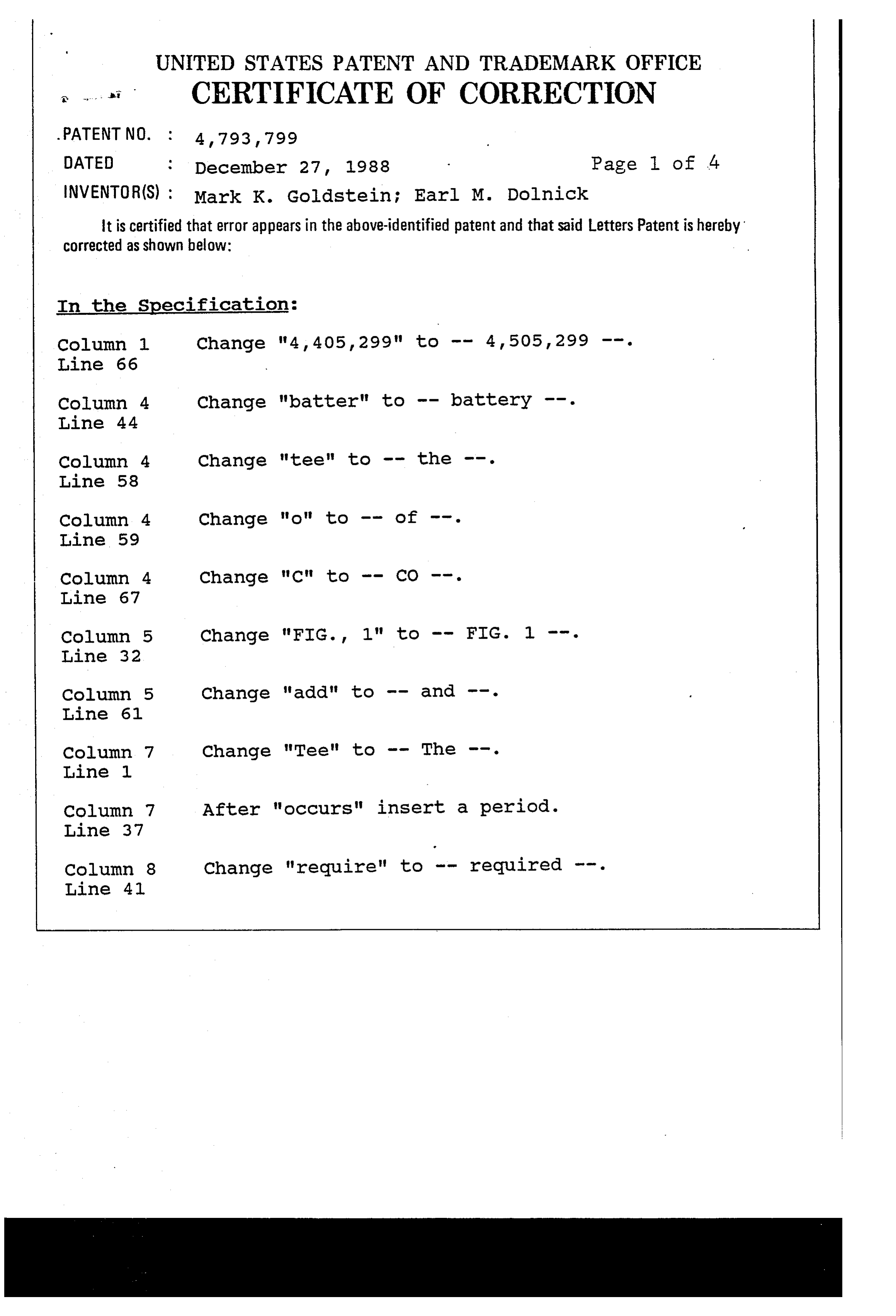
Page 30
UNITED STATES PATENT AND TRADEMARK OFFICE
.. . CERTIFICATE OF CORRECTION
Page 2 of 4
INVENTOR(S) : Mark K. Goldstein; Earl M. Dolnick It is certified that error appears in the above-identified patent and that said Letters Patent is hereby corrected as shown below:
Column 8 After "diselenide" insert a period. Line 58
Column 9 change "element" to -- elements --. Line 3
Line 27
Line 43
Line 3
Line 31
Column 21 change "descried" to -- described --. Line 29
Line 47
Line 65
Line 44
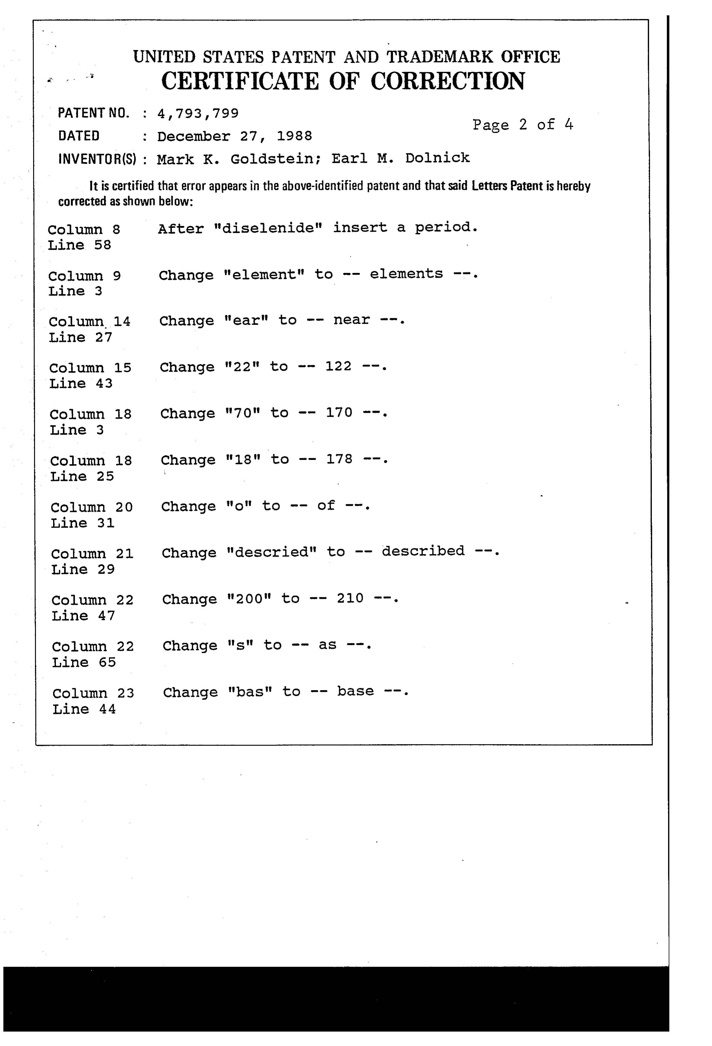
Page 31
UNITED STATES PATENT AND TRADEMARK OFFICE
a CERTIFICATE OF CORRECTION
DATED December 27, 1988 Page 3 of 4. INVENTOR(S) : Mark K. Goldstein; Earl M. Dolnick
It is certified that error appears in the above-identified patent and that said Letters Patent is hereby corrected as shown below:
Column 24 After "volt" insert a period. Line 34
Line 25
Line 36
Column 27 Change "photovoltiic" to
Column 29 change "emission , The" to -- emission. The -- . Line 32
Line 50
Column 29 change "diskshaped" to -- disk-shaped --. Line 54
Line 55
Line 5
Line 5
Line 50
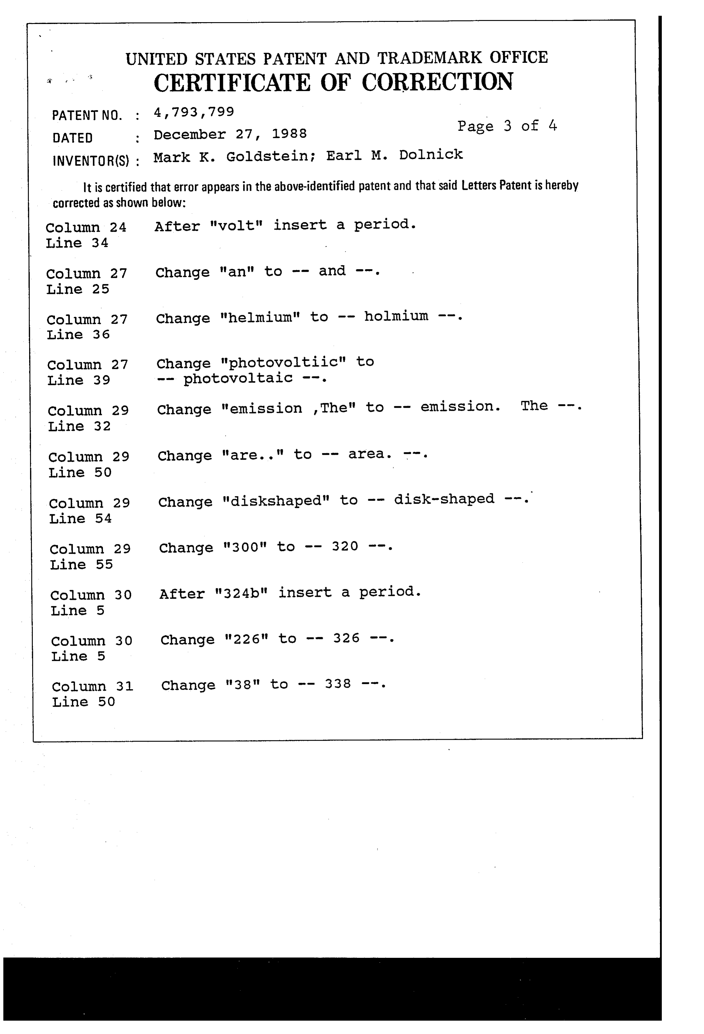
Page 32
UNITED STATES PATENT AND TRADEMARK OFFICE
a CERTIFICATE OF CORRECTION
Page 4 of 4
INVENTOR(S) : Mark K. Goldstein; Earl M. Dolnick It is certified that error appears in the above-identified patent and that said Letters Patent is hereby Corrected as shown below:
Line 12
In the Claims:
Column 34 Change "system" to -- surface --. Line 30
Column 34 Change "hearing" to -- heating --. Line 40
Column 34 After "position" insert -- with no other Line 50 source of electric power -- .
Signed and Sealed this
Twenty-ninth Day of August, 1989
DONALD J. QUIGG
Attesting Officer Commissioner of Patents and Trademarks
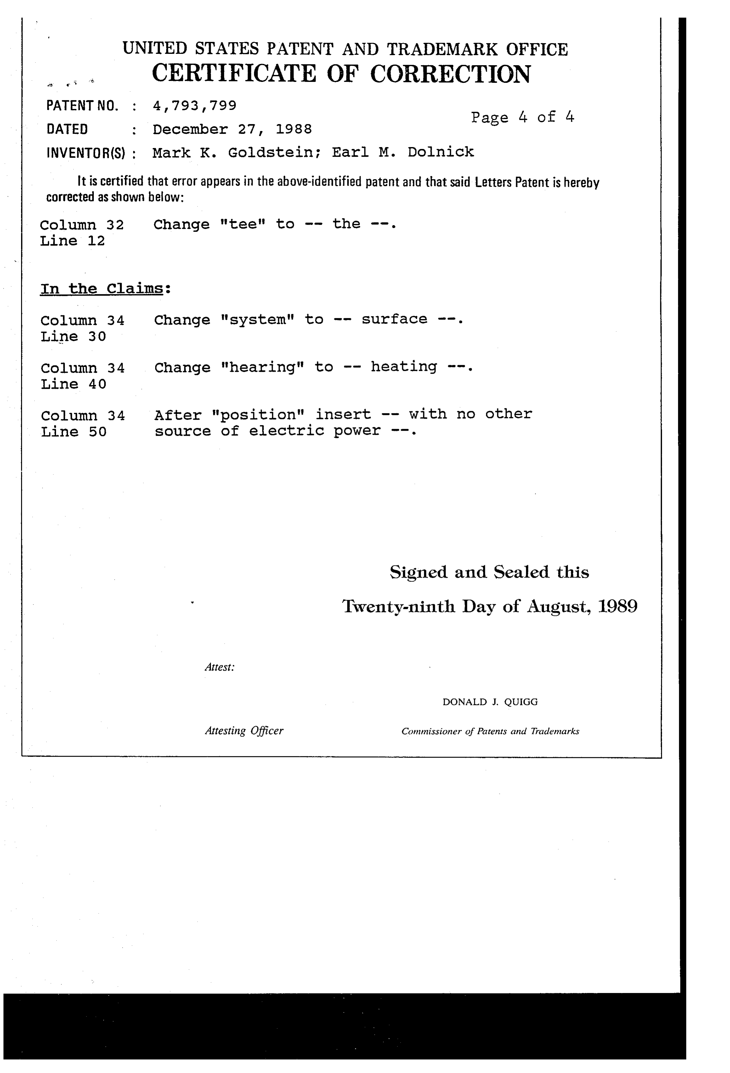
Provenance
- Collection
- Cited prior art
- Original PDF
- patentimages.storage.googleapis.com →
- Filed
- 1987-05-11
- Pages
- 32
- Method
- pdftotext (the PDF's own text layer) + pdftoppm 300dpi page scans
- Source
- Google Patents bibliographic record
- Granted
- 1988-12-27
- Inventors
- Mark K. Goldstein; Earl M. Dolnick; Quantum Group Inc
- Transcribed from
- patentimages.storage.googleapis.com →