patent · US4934927A
Perforated flame deflector
19 June 1990
Page 1 — bibliographic record
United States Patent (19) 11 Patent Number: 4,934,927 Swiatosz 45 Date of Patent: Jun. 19, 1990 54 PERFORATED FLAME DEFLECTOR 4,134,719 1/1979 Velie....... ... 431/171 4,264,298 4/1981 Simeoni. ... 431/347 75 Inventor: Edmund Swiatosz, Maitland, Fla. 4,421,474 12/1983 Meyer ..... ... 431/115 (73) Assignee: The United States of America as 4,439,134 3/1984 Olsson ..................................... 431/1 represented by the Secretary of the 4,480,988 11/1984 Okabayashi et al. ... 431/329 Navy, Washington, D.C. 4,538,530 9/1985 Whitman ............................. 110/260 (21) Appl. No.: 374,205 Primary Examiner-Carl D. Price Attorney, Agent, or Firm-Robert W. Adams 22 Filed: Jun. 22, 1989 57 ABSTRACT (51) Int. Cl. ............................................... F23M 9/06
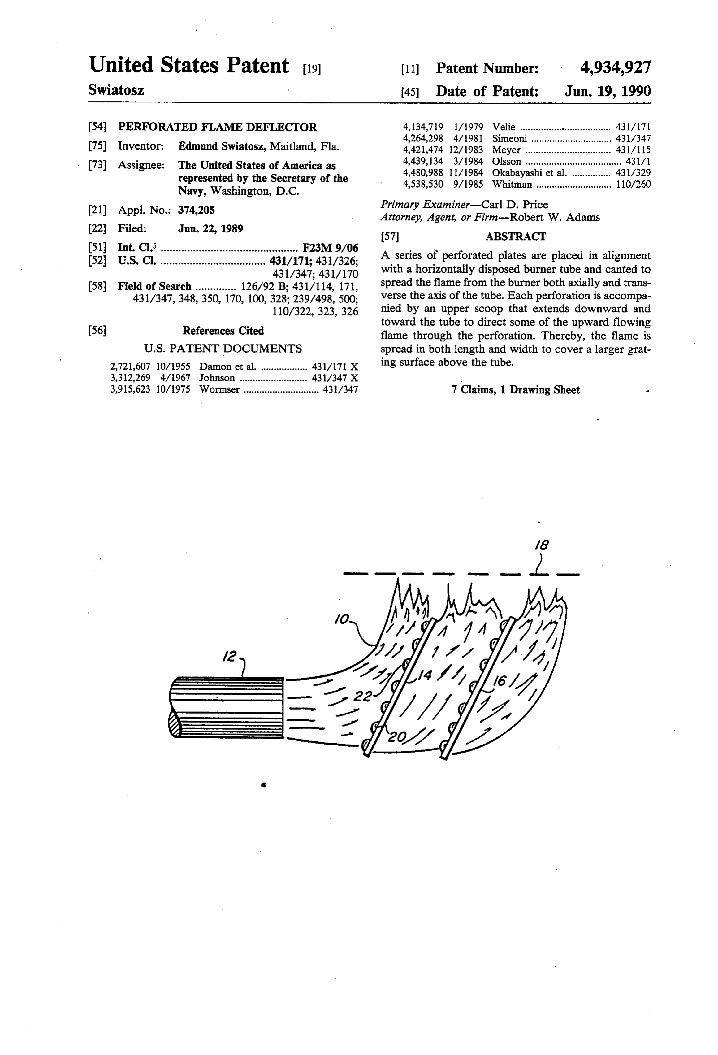
A series of perforated plates are placed in alignment (52) U.S. C. .................................... 431/171; 431/326; with a horizontally disposed burner tube and canted to 431/347; 431/170 spread the flame from the burner both axially and trans
431/347, 348,350, 170, 100, 328; 239/498,500; verse the axis of the tube. Each perforation is accompa 110/322, 323, 326 nied by an upper scoop that extends downward and toward the tube to direct some of the upward flowing (56) References Cited flame through the perforation. Thereby, the flame is
2,721,607 10/1955 Damon et al. .................. 431/171 X ing surface above the tube.
3,312,269 4/1967 Johnson .......................... 431/347 X 3,915,623 10/1975 Wormser ............................. 431/347 7 Claims, 1 Drawing Sheet
Page 2
Drawing sheet — no readable text.
Page 3
plate may reach the succeeding plate whereat the flame
PERFORATED FLAME DEFLECTOR likewise is deflected and passed, preferably with the assistance of at least one baffle/aperture combination.
BACKGROUND OF THE INVENTION The use of multiple plates will be necessary to achieve The invention relates to the field of gas burners, and maximum distribution of the flame, depending on the more specifically, is an accessory for use with such burner's capacity and pressure. burners to distribute the flame over an enhanced surface The baffle protrudes to the near-side of the plate to area. The present invention was originated for use with capture deflected portions of the flame and direct them the propane burners of the Navy's fire fighting trainers, through the aperture, and may be constructed to pro but has application wherever it is desirable to spread the 10 trude to the far-side of the plate in addition or as an flames from a gas burner over a larger area such as a alternative. Where the burner is oriented horizontally, grating surface. the flame may be spread better by employing baffles The flames from gas burners tend to columnate, only on apertures that are not within the column of which tendency reduces the effectiveness of the burners flame as it impacts, the plate, inasmuch as a baffle might for some applications. For example, an increased flame 15 obstruct the direct passage of some of the flame through area is needed if food is to be cooked uniformly on a the aperture, and orienting the baffles where they are large grill, whereas relatively narrow columns of flame used to face radially inward toward the deflected flame will generate hot spots. Accordingly, low pressure gas as a scoop to most effectively direct the captured flame grills that are used for cooking often employ burners through the aperture to the far-side of the plate. Where that are metal conduits running laterally to distribute 20 the burner oriented vertically, the flame may be spread the fuel more evenly under the grill area, and having better by employing baffles on the far-side of the plate upward opening holes whereat the gas and air are ig near the column of flame in order to deflect and spread nited to form the flames for cooking. Therein, the solu the flame after it passes through the aperture, and to tion to more evenly distribute the heat for cooking is to employ baffles on the near-side of the plate with or distribute the fuel and generate more sources of flame. 25 without baffles on the far-side for apertures more re But, in the application for which the invention origi mote from the column of flame that is rising out of the nally was intended, the burners are high volume, high burner.
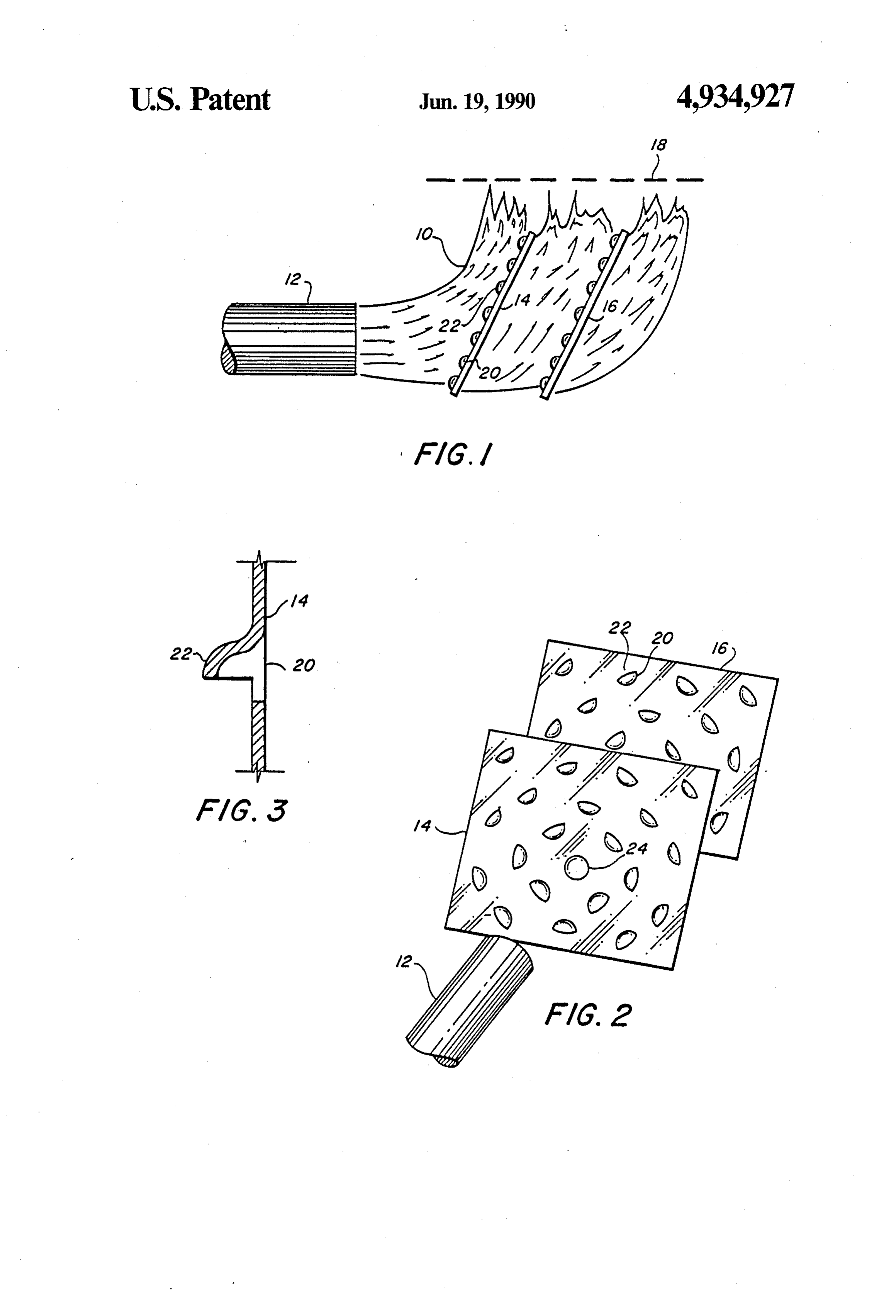
pressure systems. The flames from the burners are in tended to simulate comparatively massive fires on BRIEF DESCRIPTION OF THE DRAWINGS board ship. The flames often are expected to represent a 30 FIG. 1 shows a plan layout of the major components fire that is engulfing substantial floor space and large pieces of equipment and machinery. The advantages of of the invention in an embodiment with a horizontally the present invention as the solution to distribute the oriented burner;
flame are more highly valued where the manifold sys of FIG. 2 shows a perspective view of the embodiment FIG. 1; and, tems available to distribute the fuel for low pressure/- 35 FIG. 3 shows a close-up view of an aperture and its low volume burners, are inappropriate.
U.S. Pat. No. 4,264,298 to Giuseppe Simeoni for Hot associated baffle in the form of a scoop on the near-side plate-Type Gas Burner, is representative of a manifold of the deflection plate for directing a portion of the type, flame dispersive structures that, in addition, in flame through the aperture to the far-side of the plate. cludes a hotplate platter having an underside that is DESCRIPTION OF A PREFERRED sloped upward and away from the burner to further EMBODIMENT elongate the spread of the flame. U.S. Pat. No. 4,134,719 to Wallace W. Velie for Multi-Flame Fuel Burner For FIG. 1 shows the preferred embodiment of the inven Liquid And Gaseous Fuels, is representative of the tion configured in its original design for use with a traditional method employed with a burner to spread its 45 horizontal burner. Flame 10 is provided by tube 12 with flame, wherein a cap is placed in the path of the flame force and volume. Without plates 14 and 16 the flame forcing it to spread to the perimeter of the cap in order would form a vertical column and cover only a rela to proceed upward. Both types of structure fail to tively small surface area of grate 18. However, the achieve a substantially uniform flame over an enhanced surface area of coverage is enhanced by providing aper surface area, and are incompatible with the high pres 50 tures 20 in the plate(s) for communicating some of the sure, high volume burners used in fire fighting trainers flame longitudinally to the far side of the plate. Further, and other devices. a portion of the flame also is directed through the aper A purpose of the present invention is to satisfy a ture(s) by baffle(s) 22.
heretofore unfulfilled need for a means to engulf a large Plates 14 and 16 are resistant to flame damage. They surface area with the flame from a high capacity burner. 55 may be made of any heat resistant material that can be Further, a purpose is to provide a means to enhance the formed, shaped, drilled or otherwise worked to provide spread of a flame from a burner that is an alternative to apertures 20 and baffles 22. Suitable materials might previously available means. include ceramic and selected grades of steel. The num SUMMARY OF THE INVENTION ber of plates to be used and their respective tilt(s) as 60 shown in FIG. 1 is determined through experimentation
The invention is one or more perforated plates posi in the intended environment. Additional plates will tioned in-line with the flame from a burner and oriented provide further longitudinal spread to the flame, up to a both to defect a portion of the flame and to pass a por limit dependent on the characteristics of flame 10 which tion of the flame or deflected flame through the aper in turn is dependent on the characteristics of the burner, ture(s). A baffle accompanies at least one of the aper 65 such as its volume and force. The tilts of the plates to tures to assist in directing the flame to the far side of the the flame may be parallel to one another as shown in plate. If multiple plates are used, they are spaced apart FIG. 1, or may differ, and can be optimized through so that some of the flame that passes through the initial experimentation for the application. Further, the align
Page 4
ment of the plates in the path of the axis of tube 12 may attachment by welding or the like of baffles that have be modified by moving each plate independently up, been prepared separately.
down, and to either side, to vary the flame's surface From the foregoing description, it readily may be coverage at grate 18. The plates may be mounted in any seen that the present invention comprises a new, unique, convenient manner, a simple version of which is to and exceedingly useful flame spreader which consti attach the plates to a rod fixed to the underside of tube tutes a considerable improvement over the known prior 12 and extending forward thereof. art. Obviously, many modifications and variations of FIG. 2 displays a representative pattern of apertures. the present invention are possible in light of the above Note that in the pattern, baffles 22 are oriented to scoop 10 teachings. It is, therefore, to be understood that within flame 10 as it spreads radially and upward from the axis the scope of the appended claims the present invention of tube 12. The flame is diverted by baffles 22 through may be practiced otherwise than as specifically de apertures 20 to the far side of plate 14 and plate 16. With scribed.
What is claimed is:
respect to aperture 24 which is near or in alignment 1. Apparatus for use in conjunction with a burner with the axis of tube 12 and therefore is within the point 15 tube of impact of flame 10 on plate 14; the aperture is shown from totheenhance the spread of the flame that emanates exit end of the tube so as to envelope a larger to be without a baffle. That is to demonstrate that some or all apertures on the plate(s) that are in direct line with surface area with flames, comprising: substantially flat plate means distance from the flame 10 before it is diverted or otherwise deviates from burner, and positioned within the flame down a substantially axial direction with tube 12, may be fully 20 stream the exit end of the tube and angular to the open without a covering baffle or substantially uncov longitudinal axis of the tube, for diverting the di ered by having a relatively small baffle. Only one aper rection of propagation of the flame upwardly off ture and baffle are identified by numbers on the figure the surface of the plate means; and, for simplicity, although the apertures and baffles may be means for enhancing the spread of the flame, includ similar or identical on the plate and on each plate. Ex 25 ing means within said plate means having a plural perimentation may be used to determine the preferred ity of apertures for communicating some of said size(s), shape(s) and pattern(s) of apertures/baffles. The flame longitudinally beyond the plate means, and baffles may be oriented in any manner to achieve the deflection means having baffles protruding from desired effect, which for the present invention is to 30 the surface of the plate means toward the tube in divert a significant portion of the flame to the far side of partial covering relationship to some of the aper the plate. Since flame 10 is naturally deflected some tures for receiving some of said diverted flame and what radially from the point of impact on plate 14, and redirecting it to said aperture means; since the plates are tilted in accordance with the inven such that an area above the burner that is covered by tion to deflect the flame somewhat upward, and since 35 flame consists of the area attributable to the portion the flame tends to rise of its own accord, it may be of the flame that is diverted upward by the plate desirable to observe the flame in conjunction with the means, enhanced by the area attributable to the plates and experiment with the orientation of the baffle portion of the flame communicated beyond the plate means by the aperture means.
for individual apertures in order to achieve the preff 2. The apparatus of claim 1 wherein said tube is ori ered effect. Further, it may be desirable to position the ented horizontally, and said plate means oriented diago point of impact of the flame onto the lower part of the nal to the axis of said tube with an edge of the plate plate, as shown in FIG. 1 and FIG. 2. Thereby, the plate means being more remote from the tube than the lower would be positioned for flame 10 to interact with the edge of the plate means.
greatest number of available apertures 20 as it predomi 3. The apparatus of claim 2 wherein each baffle has a nantly tended to rise and spread. 45 respective aperture and each baffle joins said plate FIG. 3 shows a closeup cutaway view of a represen means near the uppermost portion of its aperture and tative aperture 20 and baffle 22 in plate 14. Baffle 22 angles downwardly and away from said surface to the opens downward in the figure to receive flame rising baffle's lowest point which is most remote from the upward. Also, the baffle is shown to be in substantial, surface, such that the flame is made to spread longitudi but not complete, covering relationship to aperture 20 50 nally.
which indicates that the aperture is not within the point 4. The apparatus of claim 3 wherein said baffle is of contact of the flame eminating from tube 12, and cupped, with its concave side facing downward. probably is not at the extreme edge of the plate whereat 5. The apparatus of claim 2 wherein each baffle has a the baffle would be expected to be in complete covering 55 respective aperture and each baffle joins said plate relationship to its aperture. Baffle 22 is shown in the means near the outermost portion of its aperture and shape of an elongated-S, which is preferred. Alternative angles away from said surface toward said tube whereat shapes may include a lineal slope. Consideration is the proximate part of the baffle is most remote from the given to the shape and size of the aperture when the surface, 6. The such that the flame is made to spread radially.
apparatus of claim 5 wherein said baffle is shape and size for the baffle is being selected. Aperture cupped, with its concave side facing radially inward. 20 is shown to be substantially circular, which is pre 7. The apparatus of claim 2 wherein said plate means ferred. Alternative shapes may include rectangular, such as upright rectangular in conjunction with a long, comprises a plurality of said plates, each spaced apart from the other with the first being nearest said tube and narrow baffle, and slotted rectangular in conjunction the last being most remote from the tube, such that a with a short, wide baffle. For substantially circular 65 portion aperture 20 and elongated-S baffle 22, the baffle may be tures of of the the flame that is deflected through the aper first plate may encounter the next plate, and cut and pressed from the plate. Other shapes such as a so on through the last plate. flat, lineally sloped scoop with solid sides, may require k k st k s
Provenance
- Collection
- Patents citing this work
- Original assignee
- US Department of Navy
- Pages
- 4
- Method
- pdftotext (the PDF's own text layer) + pdftoppm 300dpi page scans
- Patent office record
- patents.google.com →
- Source
- Google Patents citing-documents table
- Inventors
- Edmund Swiatosz; US Department of Navy
- Published
- 1990-06-19
- Transcribed from
- patentimages.storage.googleapis.com →