patent · US4480988
Surface combustion type burner with air supply entirely as primary air
6 November 1984
Page 1 — bibliographic record
United States Patent (19) 11 Patent Number: 4,480,988 Okabayashi et al. (45) Date of Patent: Nov. 6, 1984
54 SURFACE COMBUST ON TYPE BURNER
WITH AIR SUPPLY ENTRELY AS U.S. PATENT DOCUMENTS PRIMARY AIR 3, 169,572 2/1965 Constance et al.................. 43/329
(75) Inventors: Makoto Okabayashi, Nabari; Yasuo 3,847,534 1 1/1974 Nomaguchi et al. ............... 43/329 Takeishi, Osaka; Yoichi Higuchi, 4,340,028 7/982 Hatta et al. ....................... 126/92 R Katano; Kazuto Taguchi, Sakai, all of FOREIGN PATENT DOCUMENTS
Japan 625599 8/1927 France ................................ 431/347
73) Assignee: Osaka Gas Company, Limited, Osaka,
Japan Primary Examiner-Randall L. Green
Attorney, Agent, or Firm-Edwin E. Greigg 21 Appl. No.: 378,977 57 ABSTRACT A surface combustion type burner with air supply en 22 Filed: May 17, 1982 tirely as primary air has metallic netting defining a com bustion surface, and is characterized in that in close 51 Int. Cl. .............................................. F23D 13/14 supporting contact behind the metallic netting, substan tially all over the entire rear surface of the metallic 52 U.S. C. .................................... 431/329; 431/347;
26/92 R netting, there is disposed a punched or perforated metal (58) Field of Search ....................... 431/329, 100, 347;
base which has an open or void perforation ratio smaller 126/92 R, 92 AC, 10 D, 110 C, 110 B, 110 R; than that of the metallic netting.
239/145,418, 423,590.3, DIG. 23; 60/738,749, 2 Claims, 8 Drawing Figures
Page 2
Drawing sheet — no readable text.
Page 3
Drawing sheet — no readable text.
Page 4
Drawing sheet — no readable text.
Page 5
Drawing sheet — no readable text.
Page 6
through each perforation thereof, which will effec
SURFACE COMBUSTION TYPE BURNER WITH tively prevent the backfire phonomenon. The generally AIR SUPPLY ENTRELY AS PRIMARY AIR uniformly supplied combustible gas air mixture then undergoes abrupt flow speed retardation and laterally
BACKGROUND OF THE INVENTION 5 spreading dispersion, while passing through the metalic This invention relates to improvement of surface netting, therefore causing stable flame, even on the solid combustion type burners with single-stage air supply non-perforated area of the perforated metal base, a thus entirely as primary air, equipped with metallic small amount of combustion per unit area and therefore netting defining the combustion surface, particularly to 10 small in height, to thus substantially retain the advanta such burners suited for high combustion load. geous feature generally of the surface combustion type As conventional burners of the surface combustion burners, namely of providing generally uniform heating type there are various different ones as to the way how to provide the combustion surface, thus utilizing there all over the combustion area. Furthermore, since the for a formed ceramic product, metallic netting and so 15 ally spreadinggasdispersion combustible air mixture undergoes sufficient later and provides the flame, all forth, each of them having the respective advantages and disadvantages. It is apparent, however, that those over the burner area, small in height as mentioned utilizing the metallic netting are practically more favor above, which results in providing sufficient flame-sus able than those utilizing the formed ceramic product, in taining effect for the high-speed jet of the combustible view of lower material cost and of better productivity gas air mixture immediately upon coming out of each of owing to easy forming operation. As included in such 20 the perforations of the perforated metal base; lift of the conventional burners utilizing the metallic netting, flame is hardly to occur, even when the burner is used there indeed are different structures as using the netting under high combustion load with excessive mixing ratio in a single layer and in two or more overlapping layers, of primary air in the intention of thereby abating the but they have all been the burners for rather low com 25 noxious exhaust NOx content, to thus result in also abat bustion load. The reason for such restriction in using ing another noxious exhaust CO content as effectively such type of burners is that the higher the combustion as possible. Still further, since the perforated metal base load the more eminent becomes the problems of the higher noxious exhaust NOx content and the higher is excellent in thermal conductivity and has a larger tendency of causing backfire owing to excessive burner 30 heat capacity than that of the metal netting, any possible heating, while that the more excessively supplied the tendency of temporary and localized abnormal heating primary air in the intention of thereby solving such of the metal netting is effectively suppressed as such problems the higher becomes the tendency of causing thermal non-uniformity in the metal netting is rapidly lift of the flame to thus result in the higher noxious conducted to the perforated metal base and is there exhaust CO content. Consequently, it has convention rapidly made uniformly constant, thus to surely prevent ally been compelled to use such burners in low combus 35 the phenomenon of backfire owing to such spotwise or tion load range with restricted supply of the air. localized abnormal high temperature and therefore to SUMMARY OF THE INVENTION guarantee quite stable combustion. While this burner This invention has as its object to provide a surface provides, as above, ideal combustion as is almost opti combustion type burner without the drawbacks of the 40 mal as a surface combustion type burner, all over the conventional structures as mentioned hereinabove, as is practical range from low to high combustion load; it is particularly suited for high combustion load, thus to quite simple in structure with addition only of the perfo eliminate the drawbacks while affecting as little as pos rated metal base to a conventional burner using the sible the advantages of the surface combustion type metal netting, and high productivity can therefore be burners using metallic netting for providing the com 45 realized in its manufacture, without ruining the advan bustion surface. tage of such conventional burner using only the metal To attain the object, the surface combustion type netting, namely the low material cost and simple and burner with single-stage air supply thus entirely as pri easy manufacture.
mary air, equipped with metallic netting having a front In this respect, it may be suspected that the favorable and a rear surfaces, with the front surface defining the 50 result as above is effected simply by the perforated combustion surface, is characterized according to this metal base without any substantial synergistic effect of invention in that in close supporting contact behind the metallic netting, substantially all over the entire rear the metal netting and the perforated metal base as used surface thereof, there is disposed a punched or perfo in combination. However, various experiments done by rated metal base which has an open or void perforation 55 the inventors of this invention have attested that the ratio smaller than that of the said metallic netting. burner according to this invention is indeed far more Since the perforated metal base having the void per favorable than the burner which has no metal netting foration ratio smaller than that of the metallic netting is and has the combustion surface provided directly by the disposed in close supporting contact behind the netting, perforated metal base, with respect to backfire and suitable pressure of the combustible gas air mixture in a 60 exhaust CO content, to thus clearly show that the said mixture chamber behind the perforated metal base can result is actually realized by the synergistic effect of the thereby be sustained thus enabling to widely spread out metal netting and the perforated metal base. Detailed the combustible gas air mixture within the mixture results of such experiments are shown later in this speci chamber and ultimately to supply the gas generally fication.
uniformly all over the combustion surface composed of 65 Still other objects and advantages of this invention metal netting. Also advantageous is the fact that the perforated metal base of rather small void perforation will become apparent from the detailed description to ratio causes quite high a flow speed of the mixture follow hereunder;
Page 7
BRIEF DESCRIPTION OF THE DRAWINGS
Thus, when the fan (9) is arbitrarily operated to sup ply the burner primary air into the space or chamber
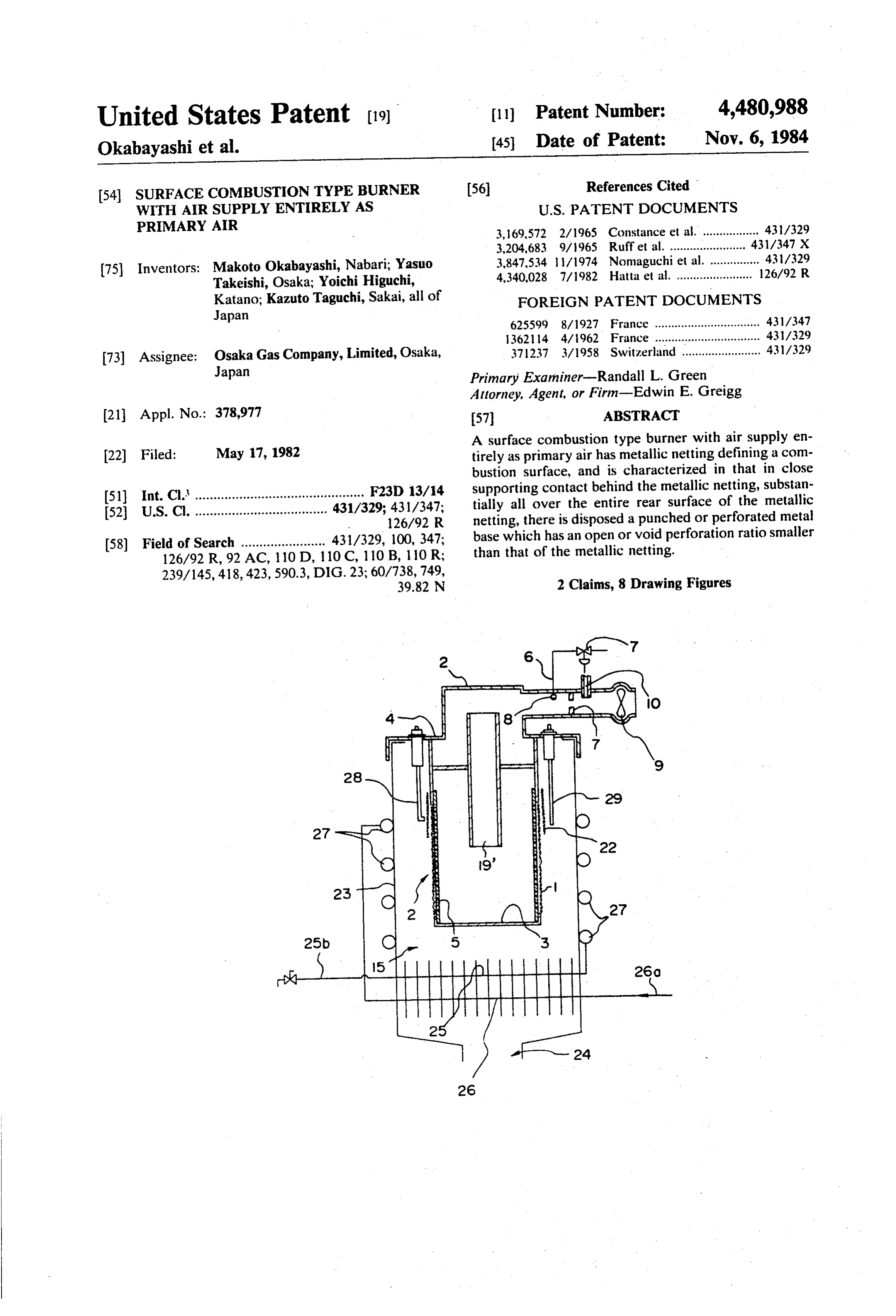
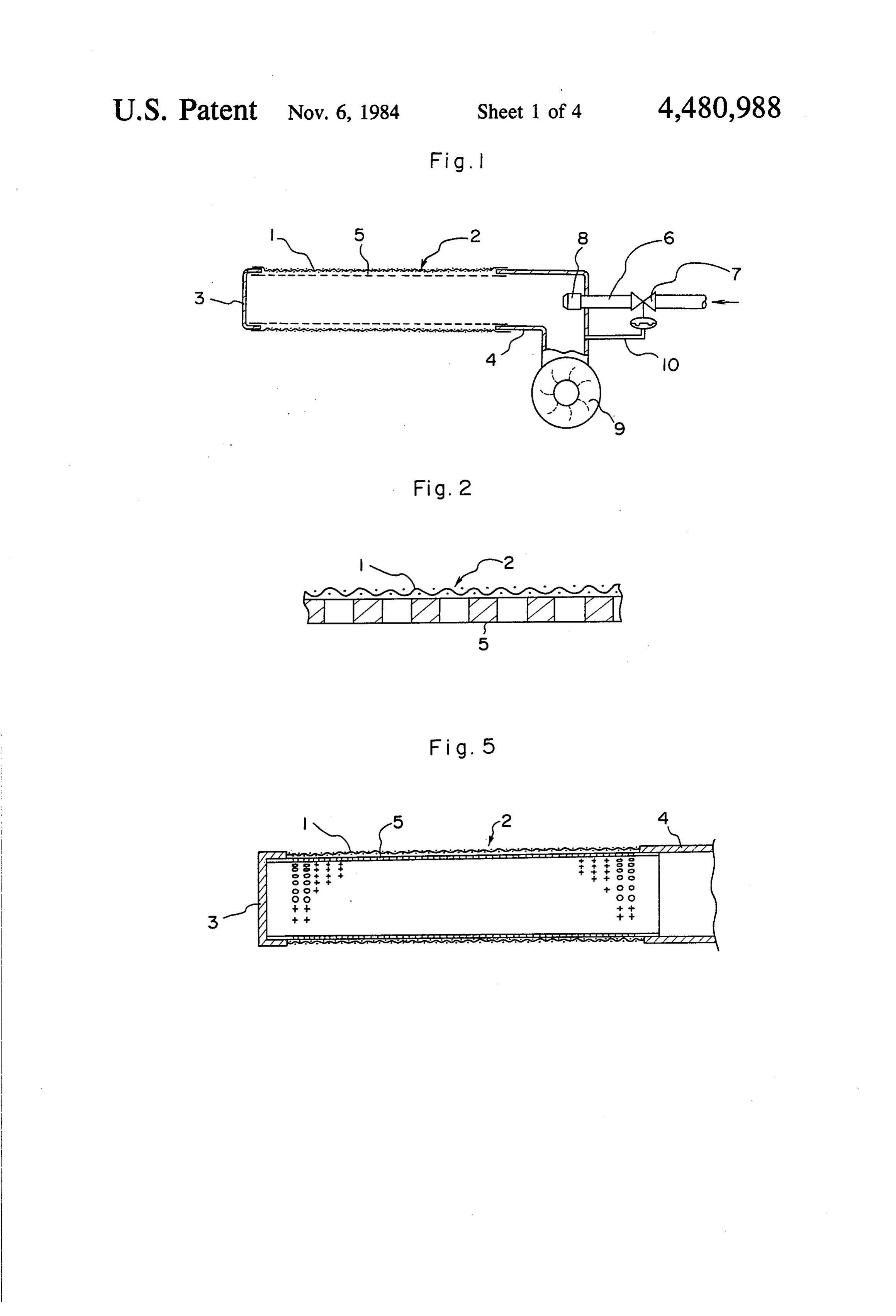
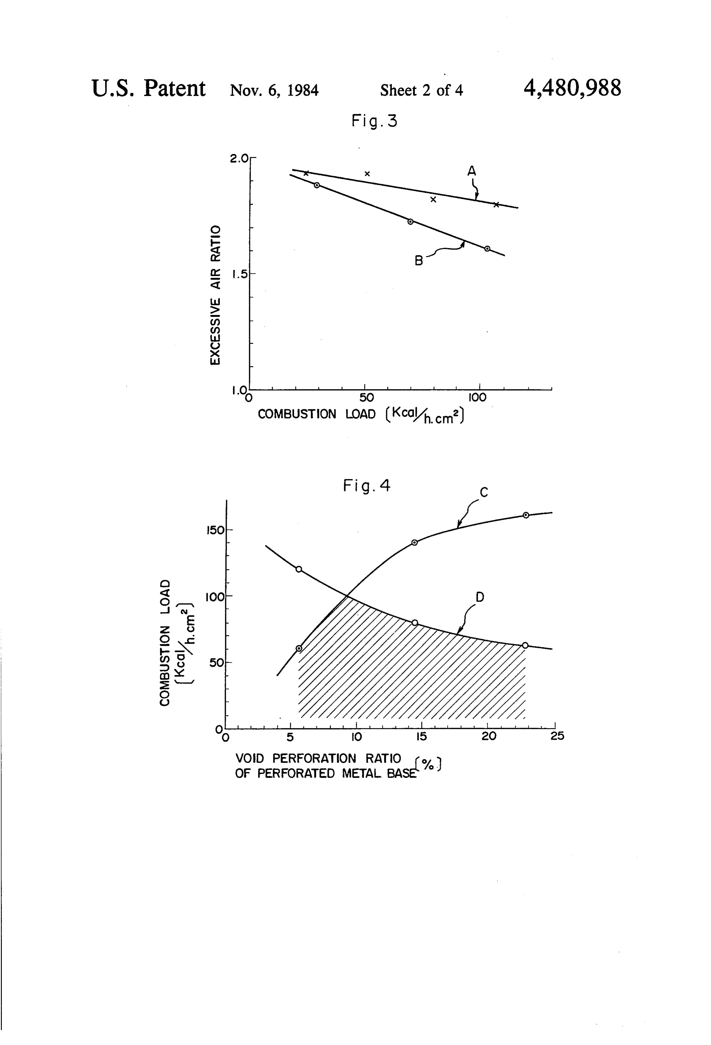
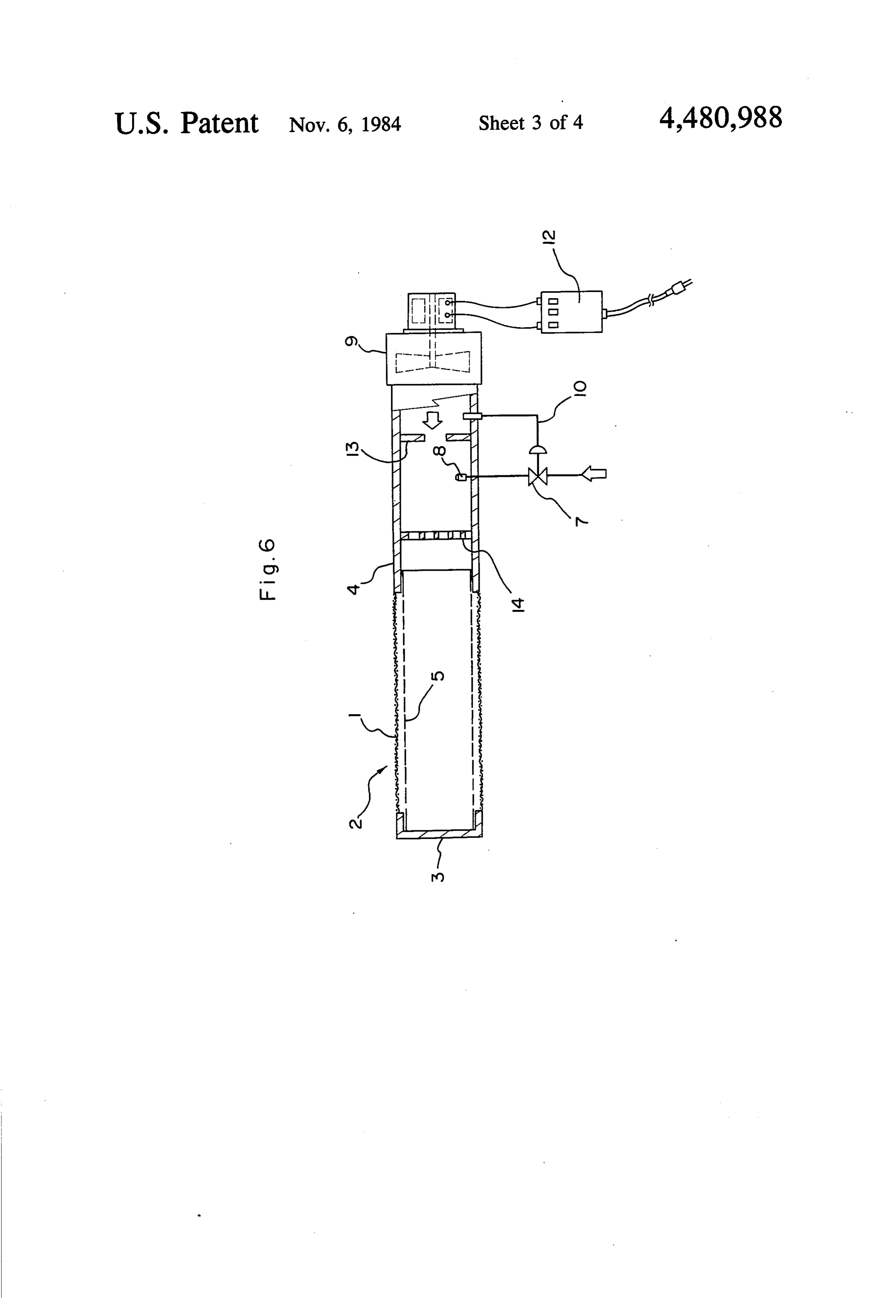
The drawings show, by way of example, some em within the burner body structural portion (4), then the bodiments of the surface combustion type burner ac fuel gas is supplied in the amount always substantially in cording to this invention, wherein: 5 proper proportion to the amount of such air as actually FIG. 1 is a schematic longitudinal sectional view of supplied, and the resultant gas air mixture is caused to an embodiment; spout through the metalic netting (1) and thereupon to FIG. 2 is an enlarged view of a portion shown in burn at the combustion surface (2). In this meanwhile, FIG. 1, as is essential to this invention; since the perforated metal base (5) of rather small void FIG. 3 is a graphical representation of test results 10 perforation ratio is provided in supporting contact be showing practically permissible upper limit of excessive hind or beneath the metalic netting (1), the gas air mix mixing ratio of primary air for a range of combustion ture is properly held within such tubular metal base (5) load, with respect to the burner according to this inven under an appropriately sustained pressure and is accord tion and a burner without metal netting; ingly spread out or dispersed therein effectively wide FIG. 4 is a graphical representation of test results 15 enough, to thus be ultimately supplied generally uni showing practically permissible maximum combustion formly all over the netting (1) area. Such gas air mixture load, without respect to the burner of this invention undergoes, while passing through the metalic netting having the perforated metal base of the respectively (1), abrupt flow speed retardation and laterally spread selected various void perforation ratios; ing dispersion along the netting (1), therefore causing FIG. 5 is a fractional sectional view similar to the 20 stable flame, even on the solid non-perforated area of lefthand end portion of FIG. 1, but showing here a the perforated metal base (5), a small amount of com modified embodiment; bustion per unit area and therefore small in height, to FIG. 6 is a sectional view similar in general to FIG. thus provide generally uniform heating all over the 1, but showing here another modified embodiment; and combustion surface area. Furthermore, since such FIGS. 7 and 8 are similar sectional views of the re- 25 widely spread flame in small height provides sufficient spective further embodiments, both adapted for applica flame-sustaining effect for the high-speed jet of the gas tion as incorporated in instantaneous water heating air mixture immediately upon coming out of each of the assembly. perforation of the perforated metal base (5); lift of the
DETAILED DESCRIPTION OF THE
flame is hardly to occur, even when the burner is used
PREFERRED EMBODIMENTS
under high combustion load with such excessive mixing ratio of primary air in the intention of thereby abating
Referring first to an embodiment of the surface com the noxious exhaust NOx content, as would inevitably bustion type burner of this invention shown in FIGS. 1 cause considerable lift of the flame in the case of the and 2, designated at (1) is a tubular metallic netting conventional burners, to thus result in also abating an having a front and a rear surfaces, with the front surface 35 other noxious exhaust CO content as effectively as pos defining the combustion surface (2). One longitudinal sible. Still further, since the perforated metal base (5) is end of the tubular metalic netting (1) is closed up by a excellent in thermal conductivity and has a larger heat solidly bottomed tubular cap (3), while the other end is capacity than that of the metalic netting (1), any possi connected, in fully open free communication, to a ble tendency of temporary or localized abnormal heat burner body structural portion (4) serving as a supply 40 ing of the metalic netting (1) is effectively suppressed as duct for a gaseous fuel as well as the air. In close sup such irregular heat is rapidly conducted to the perfo porting contact behind the metalic netting (1), substan rated metal base (5) and is there rapidly made uniformly tially all over the entire rear surface thereof, there is constant, thus to surely prevent the phenomenon of disposed a punched or perforated metal base (5), corre backfire owing to such spotwise or localized abnormal spondingly tubular in shape, which has an open or void 45 high temperature.
perforation ratio smaller than that of the same metallic In attestation of the merit of this invention, descrip netting (1) and whose longitudinal ends are securely tion is now given hereunder on the results of the experi fixed respectively to the said cap (3) and the said burner ments done by the inventors of this invention, referring body structural portion (4), both ends being fitted in to FIG. 3 wherein upper limiting lines, as actually per such mating parts. Designated at (6) is a pipe securely 50 scribed by occurrence of substantial lift of the flame, for fixed to the burner body structural portion (4) for sup keeping up the exhaust content condition of CO/- plying therethrough the fuel gas into the space within CO2s 0.01 when natural gas was used as the fuel, are the burner body structure portion (4). A zero-ballance shown as the curves in accordance with the given co type pressure regulator (7) is incorporated in this pipe ordinates which indicate the combustion load on a (6), and at a tip end of the pipe (6) there is provided a 55 given abscissa and excessive air ratio, with respect to fuel nozzle (8). To the burner body structural portion the stoicheometric air volume, on a given ordinate, thus (4) there is securely fixed a fan (9), in free communica the region immediately above the curves is the region tion with the space therewithin so as to forcibly supply off the said condition, with the value of CO/CO2 there the burner primary air thereinto. A regulator-actuating fore being slightly over 0.01 there. Curve (A) represents pressure-conducting tube (10) is provided in communi- 60 the results obtained with the burner equipped according cation with the space within the burner body structural to this invention with the perforated metal base (5) in portion (4) in a position downstream of the fan (9), for close supporting contact behind the metalic netting (1), leading the pressure to the zero-ballance type pressure and curve (B) with a reference burner equipped only regulator (7) so that the same may automatically regu with the perforated metal base (5) without combined late, in response to the pressure, the fuel supply always 65 use of any metalic netting (1). From these results of the to vary substantially in good proportion to the burner experiments, it is apparent that of the said two burners primary air regardless of any possible variation by ma the one according to this invention gives less exhaust neuvering the fan (9). CO content when supplied with excessive air in the
Page 8
intention of thereby abating exhaust-NO content, the over 15% in view of proper operation without phenom more eminent becomes the difference as the higher goes enon of backfire. All in all, it is thus known that the said up the combustion load. It is hereby demonstrated that ratio in the range of 5-15% provides the most prefera such favorable function as above is brought forth by ble results. . . . . .. . .. . . .. . . . . synergistic effect of the metallic netting (1) and the 5 The surface combustion type burner according to this perforated metal base (5) as used in combination and is invention may find, main field of its application for in thus the peculier merit of this invention. stance in instantaneous water heating assemblies, warm By the way, the shape of the combustion surface (2) air blowers and various boilers as for baths and the like, may arbitrarily be selected from the various possibilities but there is no limitation whatsoever in the field of such for instance as cylindrical, prismatic, planar and so 10 application. ... - '.
forth, and further modifications in the structure are also Further description is now given hereunder on the possible for instance as providing either one or both of modified embodiments of this invention with reference the perforated metallic base (5) and the metallic netting to FIGS. 5-8, wherein the parts identical with those in (1) in multiple overlapping layers. In either case, it the embodiment already described with reference to should be noted that if and when a gap is caused be 15 FIGS. 1 and 2 are designated, by the same reference tween the metallic netting (1) and the perforated metal numerals, and repeating the description of such parts base (5) as they are heated, owing to larger thermal are omitted as of no need. - . . .' extension of the outer netting (1) than that of the inner An embodiment shown in FIG. 5 differs from that of base (5), then harmful flaming combustion may occur in FIG. 1 only in that both ends of the metalic netting (1) such gap, and it is therefore highly desirable, for pre 20 are not fitted on outer rims of the cap (3) and the burner vention thereof, to provide the metallic netting (1) and 'body structural portion (4), respectively, as seen in FIG. the perforated metal base (5) in such manner as to al 1, but are securely fixed in longitudinal end-to-end abut ways retain their mutual close contact even when they ment against the cap (3) and the burner body structural are heated to quite high temperature range. More par portion (4), respectively. This modification is based on ticularly, it is therefore preferable to construct the per 25 the face that providing the metalic netting (1) as fitted forated metal base (5) with a material having larger on outer rims of such cap (3) and the like as in FIG. 1 thermal extension coefficient than that of the material tends to let the gas air mixture at such fitted ends flow metal of the netting (1), and to construct the metallic out along the overall facial surface of the netting (1) netting (1) and the perforated metal base (5) in cylindri : thus to build there long flames as may lead to increasing cal or tubular shape, of course both of them. By way of 30 exhaust CO: content, but that the flame generally uni example, a typical and practical combination of the form; all over the combustion surface. (2) may be ex specific materials, in terminology as prescribed in JIS, pected by providing the netting (1) as fixed in longitudi namely Japanese Industrial Standard, is the ferro snal:end-to-end abutment against the cap (3) and the like, chrome heat-resisting steel of FCH2 or the like for the thus to enable to further effectively abate exhaust CO netting (1) and the nickel-chrome heat-resisting steel of 35 content.' . . ; ; . . . . . . ‘. . ". . . . . . . SUS304 or the like for the nating perforated metal base . . Another embodiment is shown in FIG. 6, wherein in (5). a power, source circuit for the fan (9) there is provided The inventors of this invention also made various a maneuvering mechanism (12), for adjustably setting further experiments to investigate how the exhaust CO : the fan (9) rotation speed, to thereby make it possible to and NO contents are affected by the shapes of the 40, arbitrarily adjust or regulate the output. heating rate of metallic netting (1) and the perforated metal base (5). this burner and to reasonably save the power for driving Revealed from the results as favorable were those-using : the fan (9). In the burner body structural portion (4) the metallic netting (1) made of wires of 0.25-0.5 mm ... downstream: of the fan (9), there are disposed an orifice diameter in 20-40 mesh, most preferably of 0.3-0.4 mm ... (13) and a plate: (14), with multiple perforations, and diameter in 25-35 mesh, and the perforated metal base 45 longitudinally; intermediately therebetween there is (5) with 1-2 mm diameter perforations of 3-20% void disposed the fuel nozzle. (8), so that the burner air, as perforation ratio, most preferably of 5-15% that ratio. , supplied from the fan (9) and the fuel from the nozzle (8) Optimal range of the excessive mixing ratio of primary may be mixed sufficiently enough by the cooperative air in the gas air mixture was then revealed as 1.2-1.7 function; of the orifice (13) and the perforated plate (14), for the natural gas and 1.6-2.1 for the manufactured gas. 50 Theto then be supplied towards the combustion surface (2). Shown in FIG. 4 are the results of a partial series among regulator-actuating pressure-conducting, tube (10) such experiments, made under the condition of the ex is here: provided in communication with the space cessive primary air mixing ratio 1.5, using a natural gas within the burner body structural portion (4) in between as the fuel and the metalic netting (1) of 0.35 mm diame ... the orifice (13) and the fan (9), so that the mixing ratio ter wires in 32 mesh as well as the perforated metal base 55. s of the fuel gas and the burner primary air may always be (5) of 1.0-2.0 mm diameter perforations, in graphical retained within a set range, regardless of any inadver representation with the combustion load on the ordinate tent plugging of the metallic netting (1), perforated and with the void perforation ratio of the, perforated metal base. (5) and perforated plate (14) as well as any metal base (5) on the abscissa, where curve. (C), is an alteration of the fan (9) rotation; preferably in the range upper limiting line, as actually prescribed by occurrence 60. corresponding to that mentioned hereinabove as is opti of substantial lift of the flame, for the exhaust content mal for abating exhaust CO and NOx contents, namely condition of CO/CO2=0.01 and curve (D) is another the excessive primary air mixing ratio range of 1.2-1.7 entirely different limiting line for. 10 mm flame length. It for the natural gas and 1.6-2.1 for the manufactured gas. is apparent from the results shown here that the void It is thus possible with this burner of FIG. 6, thanks to perforation ratio of the perforated metal base (5) should 65 the flow-path, restricting function of the orifice (13) and preferably be not less than 5%. In addition hereto, it is the regulating-function of the zero-balance type pres further revealed from another partial series among the sure regulator:(7), to securely retain in a set range the experiments, that the said ratio should preferably be not mixing ratio of the fuel and air as supplied towards, the
Page 9
combustion surface (2), without regard that any inad and to effectively restrain any serious burning damage vertent plugging of the metalic netting (1) defining the of the combustion-surface-building material owing to combustion surface (2) and of other parts may occur or spotwise or localized heating to abnormal high temper that alteration may be caused in the amount of the ature thereof. Furthermore, what is needed to make up burner air as supplied by the fan (9), therefore to se this burner embodiment is no more than quite simply a curely provide the optimal surface combustion, for modification of particularly incorporating a tube of quite a long while, without causing any substantial lift perforated solid material or permeable porous material, of the flame, backfire or incomplete combustion. Fur and this is thus a burner quite favorable in view also of thermore, the orifice (13) causes substantial turbulance the material and manufacturing costs. Still further, con in the gas air mixture flow to thereby serve for realizing 10 structing the burner body structural portion (4) in box through mixing, this contributing to further enhance like shape, with the interior space serving as the com and gurantee the stable combustion. Still further, the bustion chamber (15), has the advantage also of effec maneuvering mechanism (12) provides quite convenient tively utilizing the heat in the combustion chamber (15) means for easily maneuvering the fan (9) rotation speed to preheat the burner primary air as supplied from the at any time to thereby adjust the heating output of the 5 fan (9) through the burner body structural portion (4). burner securely and exactly as desired, in reasonably By the way, there further is a possibility of still enhanc simple structure, and provides economy in operation ing the uniformity of the gas supply, than in the case of from saving the power for driving the fan (9). using the flow distributor tube (19) of simple uniform Still another embodiment is shown in FIG. 7, which void perforation ratio or permeable porosity all over the has a burner body structure portion (4) constructed as 20 entire surface, by particularly modifying the spacial a double-wall unit in an open-top box-like shape, and distribution of such void perforation ratio or permeable the fan (9) is connected to the space within the double porosity such for instance as making same the smaller at wall, in free communication therewith. The open-top progressive points apart the farther from the gas inlet, in interior space provided by the box-like shape portion due accordance with the flowing condition of the com (4) serves here as a combustion chamber (15). The 25 bustible gas air mixture.
metalic netting (1) and the perforated metal base (5) are Yet another embodiment is shown in FIG. 8, wherein securely bolted to the burner body structural portion use of the flow distributor tube (19) of FIG. 7, having (4) to thus fixedly lie in the combustion chamber (15). the gas-permeable wall, is replaced by use of an open Designated here at (16) is an orifice for the airflow, and end flow distributor tube (19) made of normal solid provided in association therewith as designated at (17) is 30 material, thus having the gas-impermeable wall, dis a sleeve which receives the fuel nozzle (8) in communi posed as clearly seen from FIG.8. However, as is self cation hereto. This sleeve (17) is securely bolted to the evident to those skilled in the art, this burner of FIG. 8 burner body structural portion (4) with intermediary of may possibly use the flow distributor tube (19) of gas a lid (18), in such a manner that a tip end of the sleeve permeable material. As an eminent feature, this embodi (17) is located close to the orifice (16). The orifice (16) 35 ment has a flame-sustainer metallic netting (22), dis itself is securely fixed to an open-end flow distributor posed as wrapped around as a ring of about 20 mm tube (19) made of a perforated solid material or a perme width along and radially outwardly of the combustion able porous material in cylindrical shape, and this flow surface(2)-defining tubular netting (1) near an end por distributor tube (19) is in turn securely supported to lie tion thereof of the supporting connection to the burner within the metalic netting (1) and the perforated metal 40 body structural portion (4), as made coarser than this base (5) substantially coaxially therewith, with its outer latter-mentioned netting (1), more particularly of pref peripheral surface (20) spaced a suitable distance apart erably 15-20 mesh as made of 0.35 mm diameter wires. therefrom. Thus, some portion of the combustible gas Designated in this schematic illustration at (23) is a air mixture as is supplied to one end of this flow distrib casing to define the combustion chamber (15) therein, utor tube (19) flows permeatingly through the perfora 45 with a burnt gas exhaust discharge outlet (24) formed in tions or pores to the outer peripheral surface (20) radi a bottom portion of the casing (23). Designated at (25) ally outwardly of the tube (19) while the remaining and (26) are finned water pipes disposed in the lower portion of the gas air mixture flows directly to the other portion of the combustion chamber (15). More particu end of the tube (19) longitudinally thereofas may then larly, an outlet end water pipe portion (25) is disposed flow radially outwardly and flow back in a reverse 50 upstream of an inlet end water pipe portion (26), with longitudinal direction, as illustrated by arrows, to any respect to the flow of the burnt gas, with an intermedi portion of the outer peripheral surface (20). By the way, ate water pipe portion (27) interconnecting the inlet and illustrated at (21) is a finned water pipe disposed imme outlet end portions (25), (26) being helically wrapped diately above the combustion chamber (15) so that the around the wall of the casing (23) in close contact cold water as supplied from the water pipe inlet side 55 thereto at the portion thereof corresponding to the (21a) may herein be heated up to the hot water as can effective combustion chamber (15). In this way, this thus be taken out from the water pipe outlet side (21b). whole entirety is made up as an instantaneous water It is thus possible with this burner of FIG. 7, thanks to heating assembly for heating up the water as supplied the function of the flow distrubutor tube (19), to intro from the water pipe inlet side (26a) as may then be taken duce the gas air mixture to the outer peripheral surface out thusly as hot water from the water pipe outlet side (20) of the flow distributor tube (19) through the two (25b). Designated further at (28) is an ignition plug and different paths, of such radially outward passing at (29) a flame detector, as provided for easy ignition of through the wall perforations or pores and longitudi the combustible gas air mixture and for immediate auto nally reversing detour flowing with radially outward . matic cutoff of the fuel supply in response to flame overriding at the tip end, to thus make the gas air mix 65 failure, respectively.
ture supply to the outer peripheral portion (20) uniform Provision of the flame-sustainer metallic netting (22) enough and therefore ultimately to provide quite uni as illustrated in this burner of FIG. 8 further contributes form a temperature all over the combustion surface (2) to effective prevention of the lift of flame even with
Page 10
quite excessive supply of air, to thus enable by such the other hand by radiant heat from the portion of the excessive air supply ultimately to effectively abate ex metallic netting (1) by nature of stable-flame combus haust CO and NO contents, on the basis as is now tion, and is thus stably maintained in sufficiently high described hereunder: Namely, the inventors of this in the gas. enough to sustain spontaneous ignition of temperature vention noted that when burners having no such flame We claim:
sustainer metalic netting (22) are used under consider 1. A surface combustion type burner with a single able combustion load and high excessive primary air stage ratio there is then a tendency of lift of the flame to occur prisingairasupply tubular of primary air and a fuel supply, con body portion, an elongated, perfo in a portion of the combustion surface (2) near its end of 10 rated, metal base extending from and secured to said the supporting connection to the burner body structural body portion to receive a mixture of primary air and portion (4), and made investigation to reveal the cause fuel therein, said perforated metal base having a 5-15 that the temperature of the said connection end portion percent perforation ratio, a 25-35 mesh metallic netting is so low in such case, owing to heat conduction from overlying said perforated metal base in close contact the metalic netting (1) to the burner body structural portion (4), as to fail to sustain there stable ignition of 15 therewith, ration ratio said metallic netting having a greater perfo than said metal base, and a flame-sustainer the gas. Various experiments were then made to find metallic netting out how to prevent such failure, to result in confirming metallic nettingwrapped around an end portion of said that provision of the flame-sustainer metallic netting around an end portion of saidsaid juxtaposed body portion and body portion adjacent (22) as described hereinabove serves effectively to pre 20 said metallic netting to avoid flame vent such lift of the flame, on account apparently that surface being defined by that portionlift,ofasaid combustion metallic heat conduction from the flame-sustainer metallic net ting (22) to the burner body structural portion (4) is ting. netting exposed from said flame-sustainer metallic net hindered by the presence of the metallic netting (1) 2. The burner of claim 1 wherein said flame-sustainer interposed therebetween, while that the flame-sustainer 25 metallic metallic netting (22) is intensively heated, on the one than saidnetting is 15-20 mesh, and has a coarser mesh metallic netting.
hand directly by the high-temperature tip-end portion ck k k < xk of the flame built through the metallic netting (1) and on
Provenance
- Collection
- Cited prior art
- Original PDF
- patentimages.storage.googleapis.com →
- Filed
- 1982-05-17
- Pages
- 10
- Method
- pdftotext (the PDF's own text layer) + pdftoppm 300dpi page scans
- Source
- Google Patents bibliographic record
- Granted
- 1984-11-06
- Inventors
- Makoto Okabayashi; Yasuo Takeishi; Yoichi Higuchi; Kazuto Taguchi; Osaka Gas Co Ltd
- Transcribed from
- patentimages.storage.googleapis.com →