patent · US4439134
Combustion chamber for pulsating combustion
27 March 1984
Page 1 — bibliographic record
United States Patent (19)
Olsson
(54) COMBUSTION CHAMBER FOR PULSATING (56) References Cited
COMBUSTON
75) Inventor: Karl B. Olsson, Kivik, Sweden 2,402,971 7/1946. McCollum ...................... 431/114 X 2,460,086 1/1949 Hess ............... ... 431/348 X 73 Assignee: Mareck B.V., Amsterdam, 2,585,221 2/1952 Briskin ....... ... 431/347 Netherlands 2,671,507 3/1954 Morck, Jr. . ... 431/348 3,684,424 8/1972 Zink et al. .. a sea 431/114 3,853,453 12/1974 Olsson ..................................... 431/1 21 Appl. No.: 369,018 4,045,160 8/1977 Michels ............................... 43/348
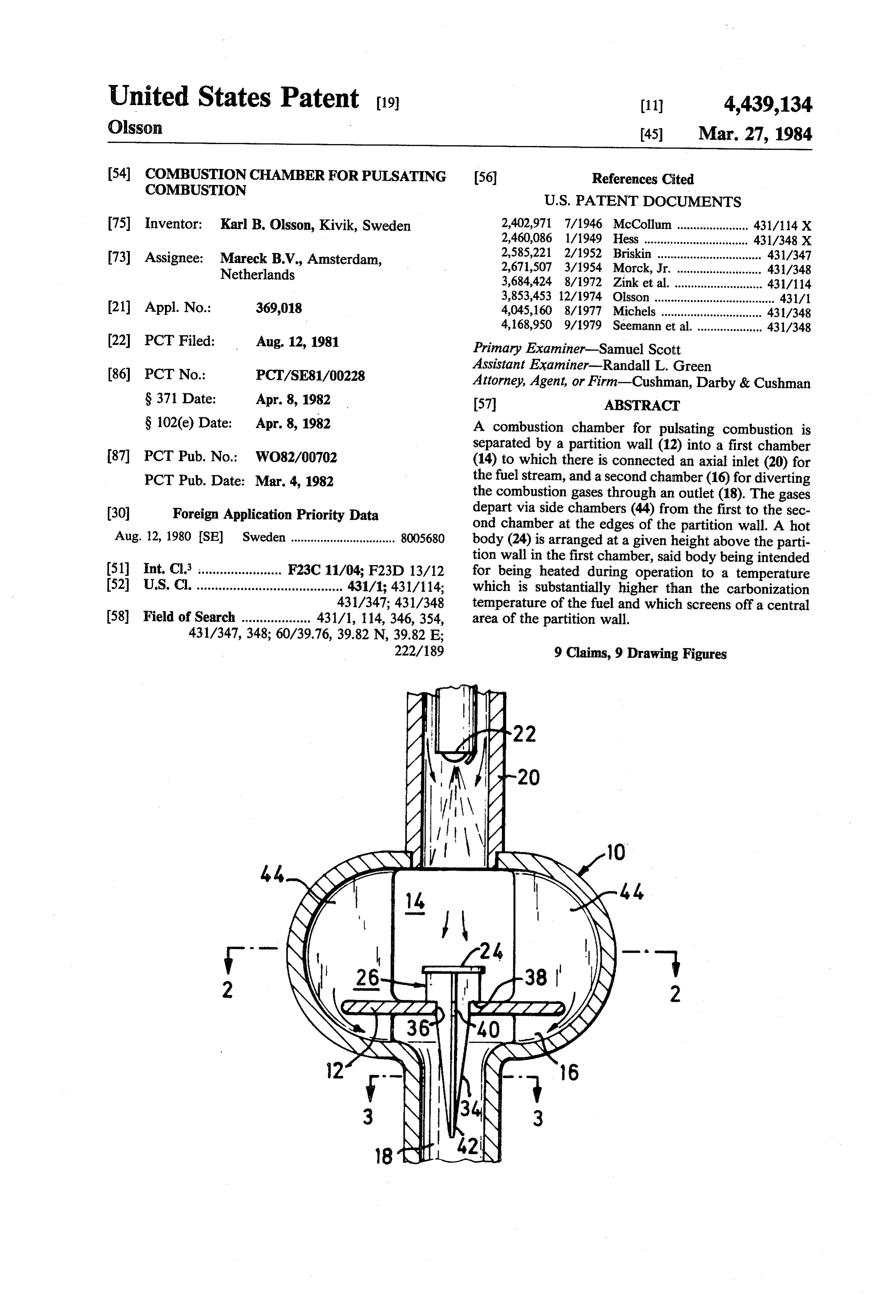
22 PCT Filed: Aug. 12, 1981 Primary Examiner-Samuel Scott Assistant Examiner-Randall L. Green (86 PCT No.: PCT/SE81/00228 Attorney, Agent, or Firm-Cushman, Darby & Cushman S371 Date: Apr. 8, 1982 57 ABSTRACT S 102(e) Date: Apr. 8, 1982 A combustion chamber for pulsating combustion is separated by a partition wall (12) into a first chamber 87 PCT Pub. No.: WO82/00702 (14) to which there is connected an axial inlet (20) for PCT Pub. Date: Mar. 4, 1982 the fuel stream, and a second chamber (16) for diverting the combustion gases through an outlet (18). The gases 30 Foreign Application Priority Data depart via side chambers (44) from the first to the sec ond chamber at the edges of the partition wall. A hot
Aug. 12, 1980 SE Sweden ................................ 8005680 body (24) is arranged at a given height above the parti tion wall in the first chamber, said body being intended 51 int. Cl. ....................... F23C 11/04; F23D 13/12 for being heated during operation to a temperature 52 U.S. C. ........................................ 431/1; 431/114; which is substantially higher than the carbonization 431/347; 431/348 temperature of the fuel and which screens off a central 58 Field of Search ................... 431/1, 114, 346, 354, area of the partition wall.
Page 2
Drawing sheet — no readable text.
Page 3
Drawing sheet — no readable text.
Page 4
Drawing sheet — no readable text.
Page 5
Drawing sheet — no readable text.
Page 6
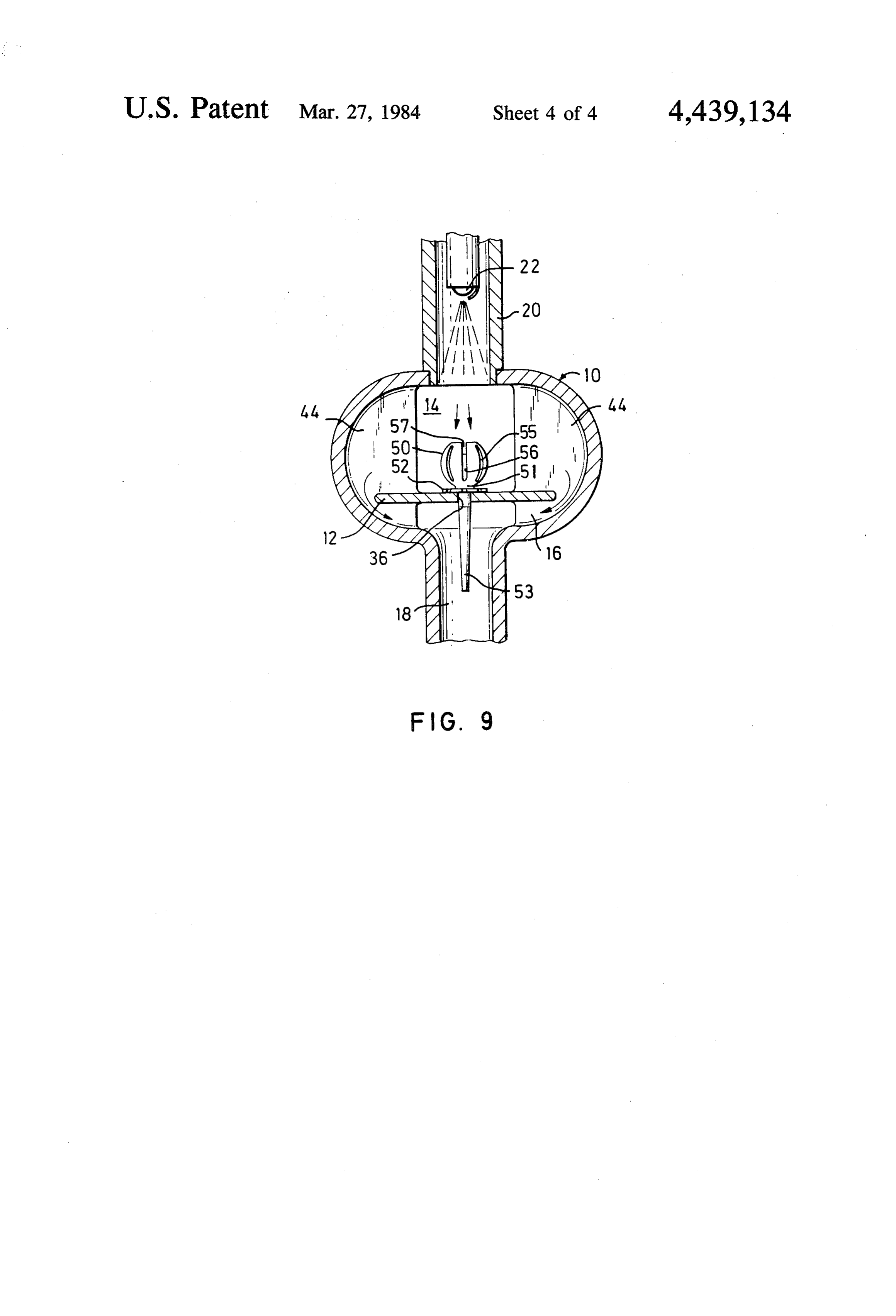
FIG. 9 shows the spherical hot body mounted in the
COMBUSTION CHAMBER FOR PULSATING combustion chamber.
COMBUSTION
DETALED DESCRIPTION
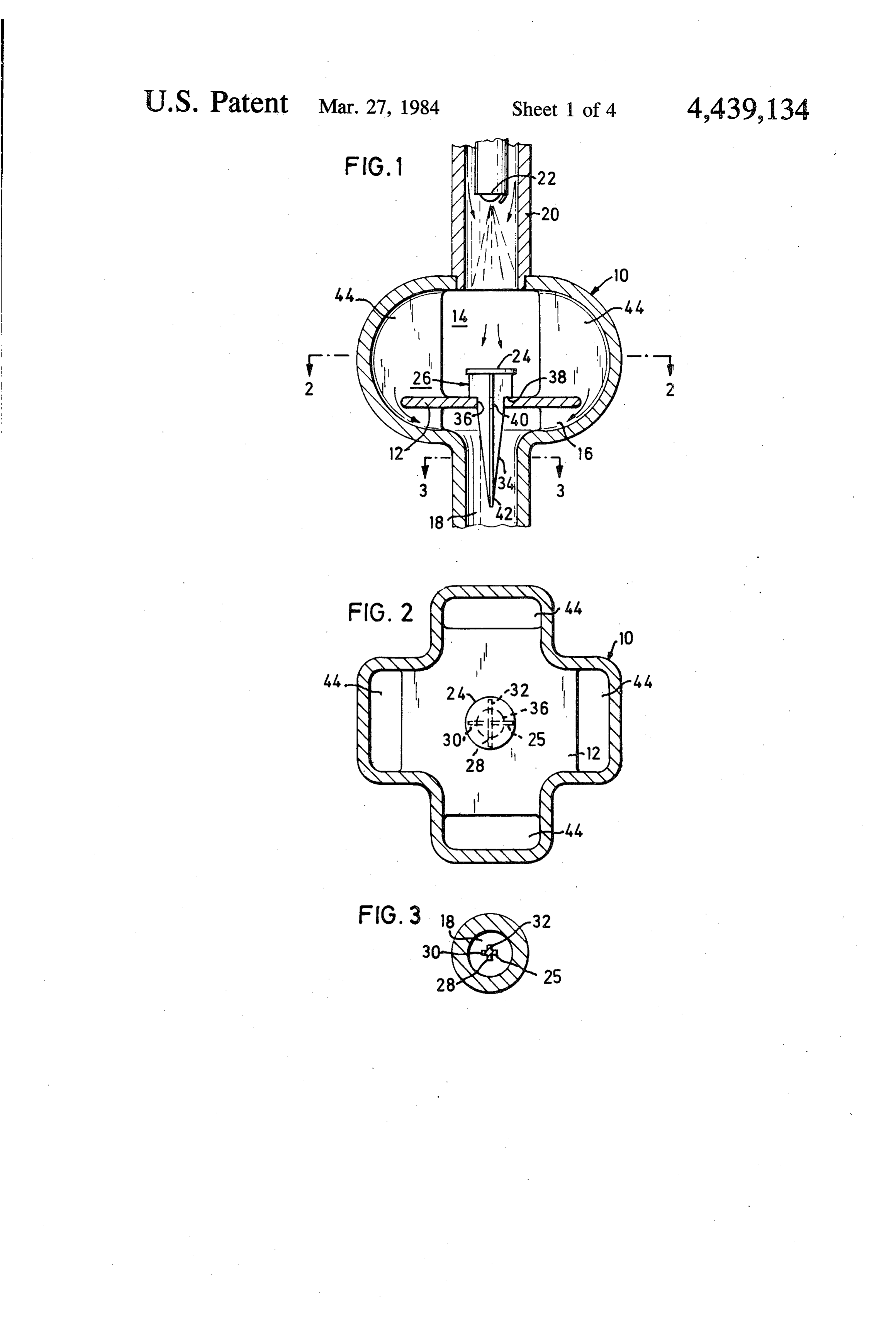
The present invention relates to a combustion cham 5 The combustion chamber 10 in FIG. 1 is of known ber of the kind having axially aligned first and second form and is divided by a partition wall 12 into a first chambers, a plurality of side chambers and a partition chamber 14 and a second chamber 16, the latter merg wall between the first and second chambers for guiding ing into an outlet 18. Combustion air is inducted via an a stream of gases over the edges of the partition wall inlet 20, in which a nozzle 22 is arranged for spraying in from the first chamber, through the side chambers and 10 fuel such as oil for admixture with the combustion air. It into the second chamber. will be seen from FIG. 1 that the spread angle of the BACKGROUND AND SUMMARY OF THE nozzle is comparatively small, resulting in that the fuel INVENTION is directed in a relatively concentrated jet into the first chamber 14.
In pulsating burners of the kind in question, there is a 15 To avoid fuel particles impinging on the partition fuel nozzle at the inlet to direct the stream of fuel axially wall 12 in its central area, and thereby cooling this area into the first chamber in a direction towards a central to an undesirably low temperature which can cause the area of the pertinent partition wall in the combustion formation of soot, a flat-shaped hot body 24 is arranged chamber. In the case where a liquid fuel such as oil is 20 at a predetermined height above the partition wall. In used, vaporization is already obtained in the inlet, but a the example shown, the hot body 24 is substantially portion of the fuel will impinge on the partition wall in circular, to give a uniform spread to the fuel irrespec the form of vapour or fuel drops. For all conditions, tive of the width of the fuel jet.
some cooling of the partition wall is obtained, and this The body 24 is carried by a foot or a support 26 in the cooling can be so heavy in some cases that the fuel 25 form of four radial flanges 25,28,30,32 arranged in a carbonizes, to be deposited as soot, which results in COSS.
operational disturbances, especially when starting. The foot 26 has an upper part situated above the wall The object of the invention is to avoid this problem, 12, and an extension portion 34 extending through a and this is achieved in accordance with the invention. central hole 36 in the wall 12, down into the second The hot body in accordance with the invention spreads 30 chamber 16 and further down into the outlet 18. out the fuel while coming up to a temperature high Each flange has a shoulder 38 resting on the wall 12. enough to be substantially above the carbonization tem After this shoulder, the width of the flanges is constant perature of the fuel by a large margin. The desired along a portion 40 for location in the hole 36 of the wall intense heating of the hot body is done with the aid of 12. Below the partition wall 12, the flanges taper off in the hot gases in the first chamber in the combustion 35 a direction towards an end portion 42. chamber, and by heat transmission from the partition The fuel-air mixture and hot gases stream out conven wall to the hot body via the foot of the latter. tionally from the central portion of the first chamber The hot body in accordance with the invention into a number of side chambers 44, over the edges of the spreads the fuel and screens off the central area of the partition wall 12 into its side chambers, down into the partition wall, which thus cannot be struck by cooling second chamber 16 and out through the outlet 18. fuel. The hot body simultaneously contributes, as is During operation, the hot body 24 is kept heated to a known in the art, to stabilizing the combustion in the high temperature which is sufficient for the body 24 combustion chamber. always to have a temperature substantially greater than To further increase heating of the hot body, its foot the carbonization temperature of the fuel. The central can to advantage be formed as a pillar extending 45 area of the wall 12 will therefore lie in a protected through an opening in the partition wall to be situated in position under the shielding hot body 24, so that the the hot gases in the outlet. central area of the wall 12 will also retain a temperature BRIEF DESCRIPTION OF THE DRAWINGS which is so high that it is substantially above the car bonization temperature of the fuel.
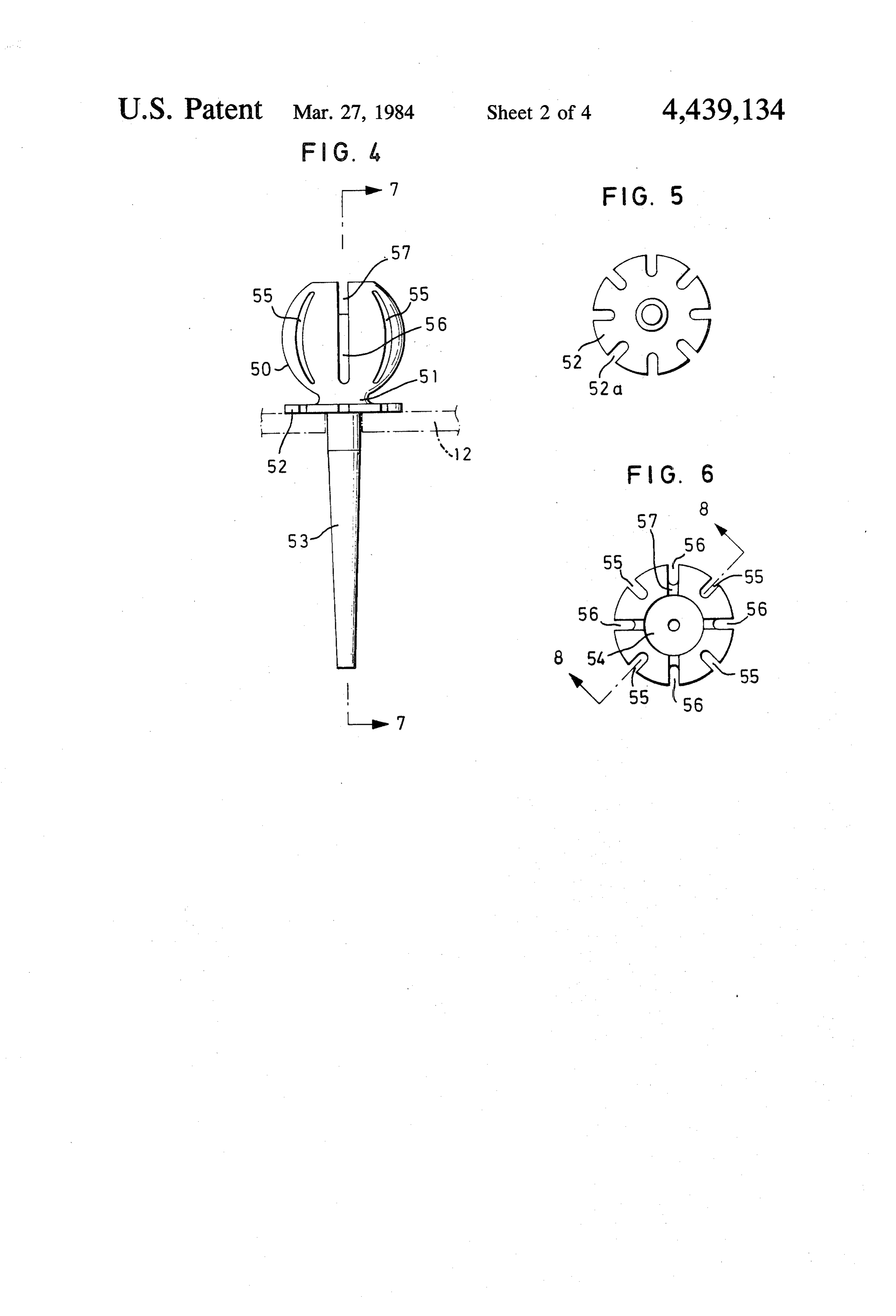
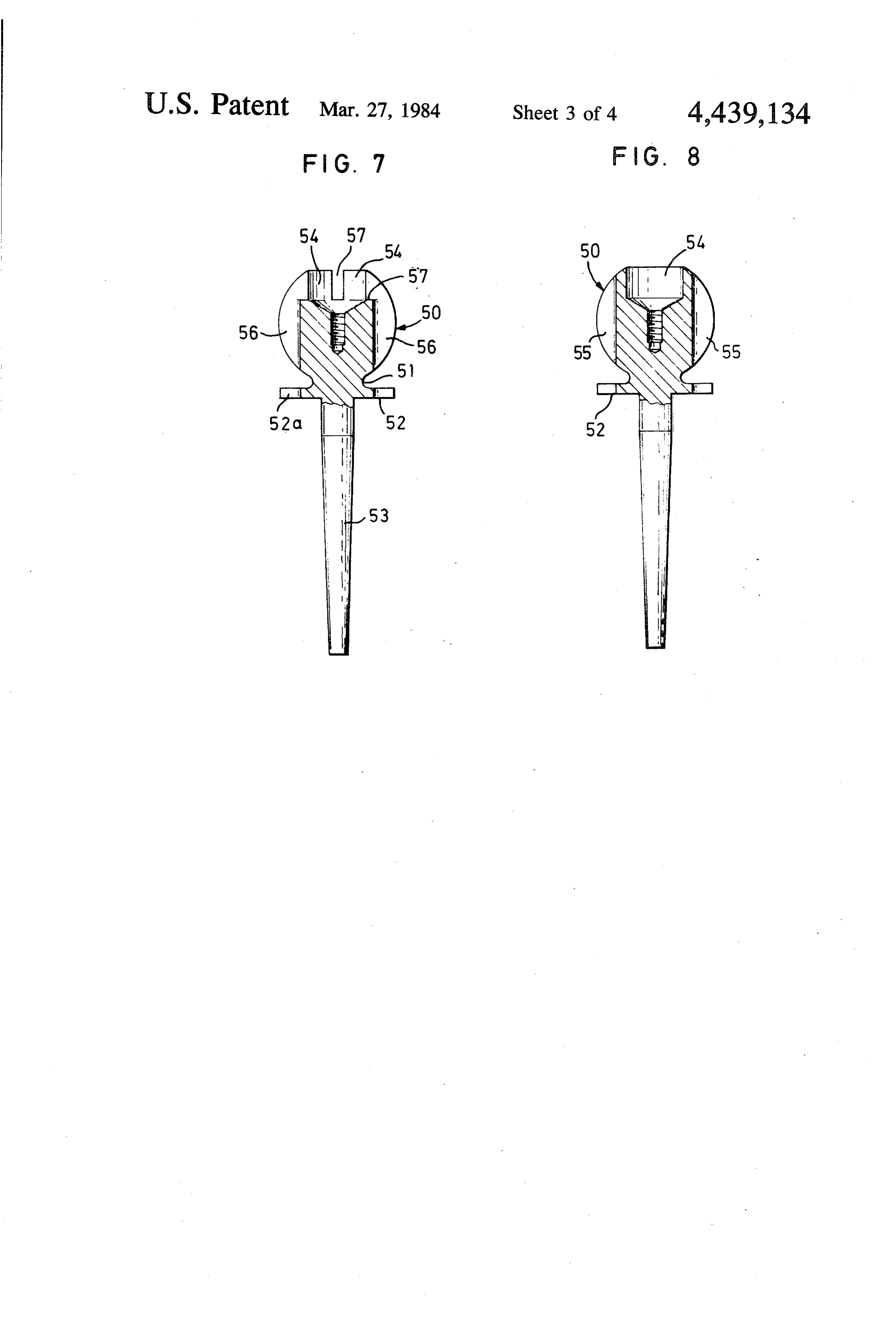
Two suitable embodiments of the invention are 50 The body 24 is heated by the hot gases in the first shown as examples on the appended drawings. chamber. Furthermore, the extended portion 34 of the FIG. 1 is a schematic section through a combustion foot or support 26 will be heated by the hot gases in the chamber for pulsating combustion, the partition wall in second chamber and in the outlet. The heat spreads the combustion chamber supporting a disc-shaped hot upwards in the foot and results in there being supple body in accordance with the invention, 55 mentary heat to keep the body 24 hot. Heat is also trans FIG. 2 is a cross section along the line 2-2 in FIG. mitted from the wall 12 to the foot 26 and further to the 1, body 24. With its foot 26the body 24 is loosely inserted FIG. 3 is a cross section along the line 3-3 in FIG. in the hope 36 in the wall 12 and therefore it can be 1, easily lifted out and up through the inlet 20 for possible FIG. 4 is a side view of the second embodiment, exchange. It is thus extremely easy to fit or remove the comprising a spherically shaped hot body with a pillar body 24.
mounted in the opening in the partition wall according The embodiment according to FIGS. 4 to 9, which to FIG. 1, has been developed further, has a substantially spherical FIG. 5 is a view seen from below of the hot body in hot body 50 carried by a short neck 51 with a flange 52 FIG. 4, 65 having slots 52a, said flange abutting the upper side of FIG. 6 is a view from above, the wall 12.
FIG. 7 is a section along the line 7-7 in FIG. 4, Below the flange 52, the neck is extended by a pillar FIG. 8 is a section along the line 8-8 in FIG. 6, and 53 which is located in the hole 36 in the wall 12 in the
Page 7
same way as the portion 34 is located in the hole 36 in 3. A combustion chamber as claimed in claim 1, char FIG. 1. acterized in that the hot body is substantially spherically The pillar 53 extends through the second chamber 16 shaped.
and down into the outlet 18 to be heated by the exhaust 4. A combustion chamber as claimed in claim 3, char gases. 5 acterized in that the upper end of the spherically shaped The hot body 50 is formed at its upper end with a hot body is provided with at least one recess for the recess having a diameter of the same order of magnitude reception of fuel drops.
as the radius of the body 50. The depth of the recess is 5. A combustion chamber as claimed in claim 4, char approximately the same as its radius. acterized in that the diameter of the recess is of the same Around its spherical surface, the body 50 has a num 10 order of magnitude as the radius of the spherical body, ber of uniformly distributed slits 55,56, the alternate slits and in that the depth of the recess is approximately 56 being in communication with the bowl-shaped recess equal to its radius.
54 via radially transverse grooves 57. 6. A combustion chamber as claimed in claim 4 or 5, For predetermined and comparatively constant oper 15 characterized in that a plurality of uniformly distrib ating conditions, the flat-shaped hot body 24 according uted, axial slits are made in the spherical surface of the to FIGS. 1 to 3 functions completely satisfactory for body. - providing a reliable start and stable operation, and for 7. A combustion chamber as claimed in claim 6, char avoiding soot formation in the first chamber on the acterized in that at least some of the slits communicate partition wall 12. .. . ... . with the recess via radial grooves. On the other hand, if the operating conditions vary, 20 of8.a fuel-air
In a combustion chamber for pulsating combustion mixture of the type including an inlet and an interalia with different types of fuels and varying loads, the spherically shaped hot body 50 in FIG. 4 affords outlet having a common axis, a first chamber in commu greater flexibility and security. nication with said inlet and of larger cross-section than I claim: - 2 said inlet, a second chamber in communication with said 1. A combustion chamber for pulsating combustion of outlet and of larger cross-section than said inlet, a plu
rality a fuel-air mixture, the combustion chamber having a substantially of side chambers, and a partition wall lying in first chamber, a second chamber and a plurality of side rating said first a radial plane relative to said axis and sepa chambers and including an inlet and an outlet having a having edges over and second chambers, said partition wall common axis and providing substantially axial inflow of 30 chamber through saidwhich side gases flow from said first chambers into said second the fuel-air mixture to the first chamber and substan chamber, the improvement comprising means for pre tially axial outflow for the second chamber, as well as a venting impingement of fuel particles on said partition partition wall situated substantially in a radial plane wall and adapted to be heated by hot gases, said means relative to said axis and separating the inlet and outlet including a fuel-spreader portion disposed in said first chambers to guide the stream of gases over the edges of 35 chamber between said inlet and said partition wall for the partition wall from the first chamber via the plural absorbing heat from said first chamber to be heated to a ity of side chambers to the second chamber, character temperature greater than the carbonization temperature ized in that an elongated member extends axially of the fuel and a foot portion extending from said fuel through a central opening in the partition wall and spreader portion through said second chamber and into through the second chamber and into the outlet so as to said outlet for absorbing heat from said second chamber be heated by the gases, the member having an end dis and for transmitting such heat to said fuel-spreader posed between said partition wall and the inlet, said end portion. . having associated therewith a hot body located in the 9. A combustion chamber as in claim 8 wherein said first chamber to serve as a hot fuel spreader. means is an elongated member extending through a 2. A combustion chamber as claimed in claim 1, char- 45 central opening in said partition wall and removably acterized in that the hot body has a concave striking supported by said partition wall.
surface facing towards the inlet for the fuel drops. k k k k s
Provenance
- Collection
- Cited prior art
- Original PDF
- patentimages.storage.googleapis.com →
- Filed
- 1981-08-12
- Pages
- 7
- Method
- pdftotext (the PDF's own text layer) + pdftoppm 300dpi page scans
- Source
- Google Patents bibliographic record
- Granted
- 1984-03-27
- Inventors
- Karl B. Olsson; Mareck BV
- Transcribed from
- patentimages.storage.googleapis.com →