patent · US4264298
Hotplate-type gas burner
28 April 1981
Page 1 — bibliographic record
United States Patent (19) 11 4,264,298 Simeoni 45 Apr. 28, 1981 (54) HOTPLATE-TYPE GAS BURNER 1,598,996 9/1926. Wheelock ............................ 239/559 2,499,707 3/1950 Warren ...... ... 126/39.11 76 Inventor: Giuseppe Simeoni, Monte Riondo 3, 2,847,988 8/1958 Hess ....... ... 126/39 H. Santa Maria di Negrar, Italy 2,870,828 1/1959 Hess ........... ... 126/39 H. 21 Appl. No.: 877,349 2,870,829 1/1959 Williams ................ ... 126/39 H. 3,754,853 8/1973 Braucksiek et al. ................. 431/347 22 Filed: Feb. 13, 1978 3,799,142 3/1974 Jensen ................................. 126/39 J (30) Foreign Application Priority Data Primary Examiner-Samuel Scott
Feb. 17, 1977 IT Italy ............................... 6734.8 A/77 Assistant Examiner-Wesley S. Ratliff, Jr. Jan. 30, 1978 IT Italy ............................... 19763 A/78 Attorney, Agent, or Firm-Michael J. Striker 5 Int. Cl....................... F23D 13/12; F02M 39/00; 57 ABSTRACT
F24C3/00 A gas burner for cookers the essential feature of which 52 U.S.C. ................................. 431/347; 239/553.3; is the enlargement of the body of the burner to form a 126/39 J flat plate equivalent to a real hotplate the inside of 58 Field of Search ................. 126/39 J, 39 K, 39 H; which is heated by the flame in such a way that the 431/347; 239/559, 553.3, 520 flame heats the plate by conduction, and further, the (56) References Cited heat reaches this hotplate from the central area of the
103,222 5/1970 Meiggs .............................. 239/553.3 9 Claims, 3 Drawing Figures
'N . ge W s 23
Page 2
Drawing sheet — no readable text.
Page 3
Drawing sheet — no readable text.
Page 4
4,264,298 - 2 . .. . . . . . . . .. .
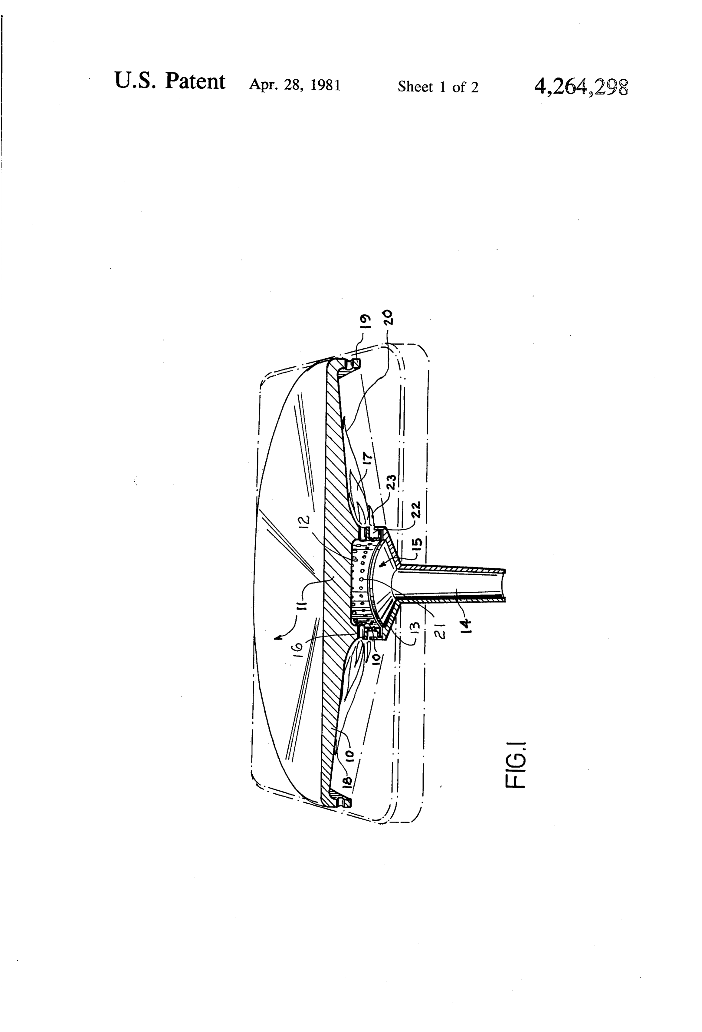
The body (10) appears as a flat top (11) like an ordi
HOTPLATE-TYPE GAS BURNER nary hotplate the lower part of which consists of the "neck" (12) which, resting in the cup-shaped end (13) of
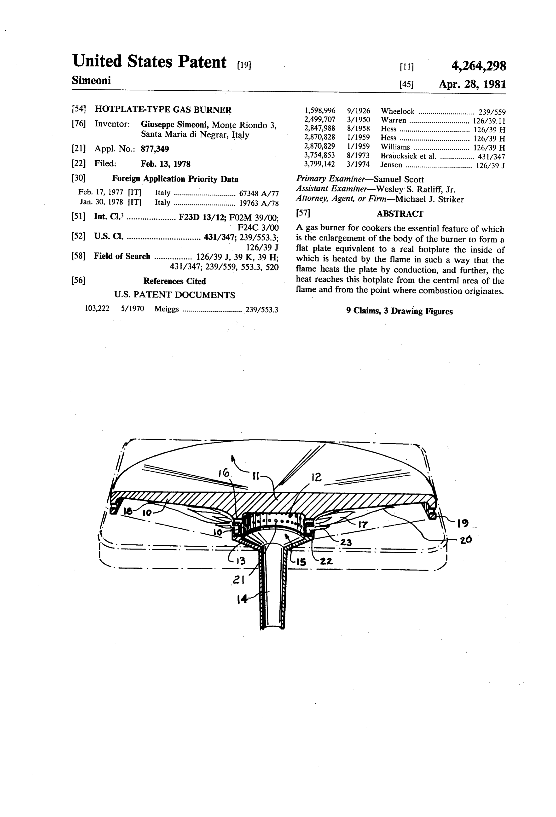
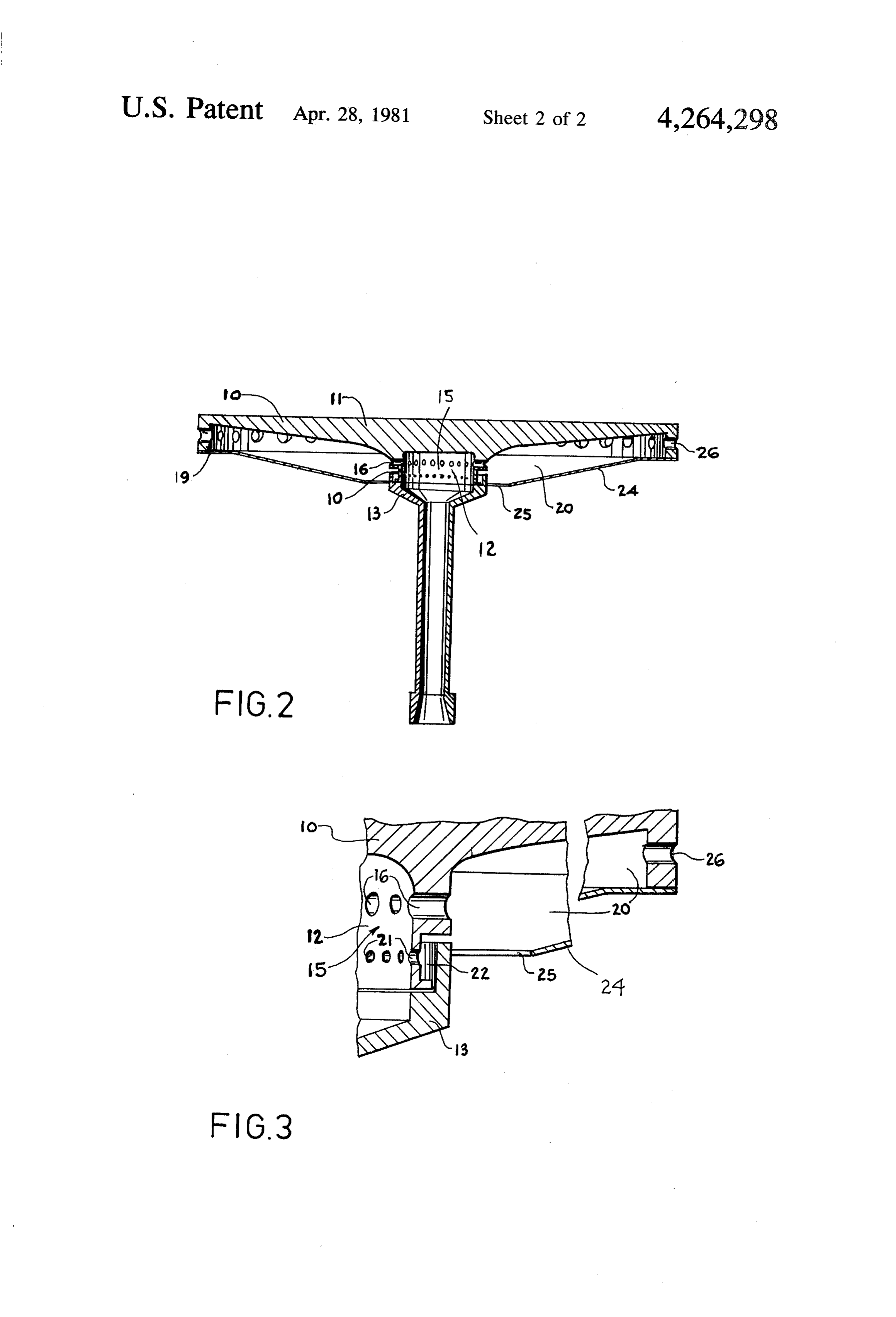
In the case of the ordinary burner for gas cookers, the the central, hollow column (14), forms a real burner. pans, or metal plates if used, are placed above the The gas flows through the central column, the lower burner and receive heat from the tips of the flame thus end of which is shaped to fit into an ordinary nozzle remaining at some distance from the central zone where (not shown) connected to the gas main, and enters the combustion takes place. chamber (15) while from the apertures placed ringwise As the body of the burner is not adequately in (16) the flame (17) touches the lower surface (18) of the contact, either structurally or in any other way, with 10 plate (11). - the cooking pan or with an intermediate metal plate if The perimeter edge (19) encloses a kind of combus used, the heat from the central zone where combustion tion chamber (20) within which the full length of the originates becomes to a considerable extent lost in the flame is contained. The apertures (21) open onto the surrounding atmosphere and thus little used. pre-combustion chamber (22) which creates the stabiliz The above invention exploits not only the heat from 5 ing flame (23). - the tip of the flame but also that from the hottest com FIG. 2 a vertical section through the middle, and bustion point, thus greatly increasing the thermal yield FIG.3 a detail of FIG. 2, show the burner-hotplate with as will be explained below. the same numbering for common or similar parts as that This invention envisages a burner the body of which 20 given to FIG. 1.
takes the form of a cooking plate or, expressing it differ The insulating shield (24) underneath the plate is ently but without altering the concept, a burner is joined to the perimeter edge (19) and has ring-shaped formed within the cooking plate. air intakes (25). The presence of this shield further re A particular feature consists in the fact that the body duces dispersion of heat into the room. of the burner, comprising the gas, or air-gas mixture, 25 The apertures (26) cut into the perimeter edge allow chamber, from which the flame orignates, is extended to burnt gas to escape and act as a flue. form a kind of flat head placed above the circular flame, As the description clearly explains, being structurally this head actually being equivalent to a hotplate. a part of the whole, the "body" (10) acts simultaneously The actual burner therefore appears as a "neck" in as a hotplate and as a burner transmitting heat, by con one with the plate; the flame issues from above the neck 30 duction, from the hottest parts of the burner and from and directly heats the underneath of the plate. the hottest parts of combustion to the hotplate and from Around the edge of this hotplate there is a raised edge there to the pans, or whatever stands on top of it, reduc projecting inwards so that a kind of combustion cham ing to a minimum the dispersion of heat into the sur ber, enclosing the full length of the flame, is formed rounding air and thus considerably increasing thermal between the projecting edge, the inside of the plate and 35 the neck. As executional forms of the invention are here de The foregoing description shows that the external scribed merely as examples, without thereby limiting it surface of the hotplate receives heat from the hottest to these, a request for industrial exclusivity must include combustion area of the actual burner by conduction, all equivalent applications of the concept described, and heat direct from the flames touching the underside of 40 all equivalent products created and/or in operation the plate, and heat collected inside the combustion according to one or more of the characteristics indi chamber. cated in the following claims. Even if, for practical reasons, this "cooking body” I claim:
which is simultaneously a hotplate and a burner, is con 1. A heating device, comprising a plate-shaped wall structed in two or three pieces, the fit, contact surfaces 45 having an inside surface and an outside surface so that and heat transmissions is such as to maintain the amount an article to be heated can be supported on said outside of heat, transmitted by conduction to the hotplate, prac surface and said plate-shaped wall can serve as a hot tically unaltered. plate, said inside surface of said plate-shaped wall hav The shape given to the hotplate may vary as desired, ing a central portion; a ring-shaped wall of one-piece and may be circular, rectangular or many-sided, while 50 with said plate-shaped wall, said ring-shaped wall ex the gas may issue either from a central nozzle, as in the tending transversely from said inner surface of said case of the "neck' described above, or from two or plate-shaped wall in the region of said central portion so more distributors suitably placed barycentrically to the as to bound a central space communicable with a source hotplate, and the same applies to the flame issuing from of combustible material and being provided with a plu a single nozzle or from more than one. 55 rality of passages through which flame resulting from On its inside, at the point where the flame originates, combustion of the combustible material can leave said the plate is arc-shaped so as to convey the flame and the central space so that said ring-shaped wall forms a heat waves radially and cause them to reach the whole burner which is of one piece with said hotplate and surface area of the plate. thereby the heat is transmitted to said hotplate not only One execution of the invention envisages application from the tips of the flame but also from the point to the lower part of the hotplate of an insulating screen wherein the flame leaves said passages; and a bottom which starts from the bottom of the downward and wall bounding said central space from below and hav inwardly projecting edge, enclosing the above-men ing an inlet operative to receive therethrough said com tioned combustion chamber except for a circular air bustible material.
intake ring around the "neck' of the burner-hotplate. 65 2. A heating device as defined in claim 1, wherein said The attached sketches further illustrate the invention outside supporting surface has a flat cross-section. and show two types of execution. 3. A heating device as defined in claim 1, wherein said FIG. 1 is a partially cut perspective view. passages are circumferentially spaced from each other
Page 5
and located adjacently to the inside surface of said 7. A heating device as defined in claim 6, wherein said plate-shaped wall. outlet means comprises a plurality of through-going 4. A heating device as defined in claim 3; and further openings provided in said peripheral wall portion, each comprising a further wall closing said combustion of said openings having a first end open into said com chamber, thereby preventing loss of heat therefrom. bustion chamber and a second end open into the exte 5. A heating device as defined in claim 1, wherein said rior of the latter.
plate-shaped wall has a peripheral wall portion extend 8. A heating device, comprising a plate-shaped wall ing transversely to the remainder portion of the same having an inside surface and an outside surface so that and being of one piece with said remainder portion, said 10 an article to be heated can be supported on said outside surface and said plate-shaped wall can serve as a hot peripheral portion together with said remainder portion plate, said inside surface of said plate-shaped wall hav of said plate-shaped wall forming a combustion cham ing a central ber communicating with said central space through said peripheral wallportion, portion said plate-shaped wall having a extending transversely to the passages.
remainder portion of 6. A heating device, comprising a plate-shaped wall 15 with said remainder portion, the same and being of one piece having an inside surface and an outside surface so that together with said remainder said peripheral portion portion of said plate an article to be heated can be supported on said outside shaped wall forming a combustion chamber; surface and said plate-shaped wall can serve as a hot shaped wall of one-piece with said plate-shapeda wall, ring plate, said inside surface of said plate-shaped wall hav said ring-shaped wall extending transversely from said ing a central portion, said plate shaped wall having a 20 inner surface of said plate-shaped wall in the region of peripheral wall portion extending transversely to the said central portion so as to bound a central space com remainder portion of the same and being of one piece municable with a source of combustible material and with said remainder portion, said peripheral portion being provided with a plurality of passages which com together with said remainder portion of said plate municate said central space with said combustion cham shaped wall forming a combustion chamber; a ring 25 ber and through which flame resulting from combustion shaped wall of one-piece with said plate-shaped wall, of the combustible material can leave said central space said ring-shaped wall extending transversely from said so that said ring-shaped wall forms a burner which is of inner surface of said plate-shaped wall in the region of one piece with said hotplate and thereby the heat is said central portion so as to bound a central space com transmitted to said hotplate not only from the tips of the municable with a source of combustible material and 30 flame but also from the point wherein the flame leaves being provided with a plurality of passages which com said passages, said passages being circumferentially municate said central space with said combustion cham spaced from each other and located adjacently to the ber and through which flame resulting from combustion inside surface of said plate-shaped wall; a further wall of the combustible material can leave said central space closing said combustion chamber thereby preventing so that said ring-shaped wall forms a burner which is of 35 loss of heat therefrom; and a further inlet operative for one piece with said hotplate and thereby the heat is permitting air from exterior of said combustion cham transmitted to said hotplate not only from the tips of the ber to enter the latter.
flame but also from the point wherein the flame leaves 9. A heating device as defined in claim 8, wherein said said passages; and outlet means for evacuating gases further inlet is provided in said. further
wall.
from said combustion chamber.
Provenance
- Collection
- Cited prior art
- Original PDF
- patentimages.storage.googleapis.com →
- Filed
- 1978-02-13
- Pages
- 5
- Method
- pdftotext (the PDF's own text layer) + pdftoppm 300dpi page scans
- Source
- Google Patents bibliographic record
- Granted
- 1981-04-28
- Inventors
- Giuseppe Simeoni
- Transcribed from
- patentimages.storage.googleapis.com →