patent · US3312269
Infra-red radiant heater and grid therefor
4 April 1967
Page 1
Drawing sheet — no readable text.
Page 2
April 4, 1967 A. C. W. JOHNSON 3,312,269
INFRA-RED RADANT HEATER AND GRID THEREFOR
Original Filed May 28, 1964 6 Sheets-Sheet 2
sessetts
2 : EEEEEE ife
6. GEOSE). E; N
Sega
(OIE)in re. Giri)\92 \
SSill. O Iss t W SI Fo o N
were2 N
6 NE O -2
Nkre i. N., o 9 0 d c
N so so s o 8 s
N soo o o oa N
No. 3. s d 9 N N.' o . . . .
s N
8 d 0
.N FIG. I.
N 8 N No t 3. Ng o o 2O . . to. . . . . ob
E. NVENTOR
ARTHUR C.W. JOHNSON
AITORNEY
Page 3
Drawing sheet — no readable text.
Page 4
April 4, 1967 A. C. W. JOHNSON 3,312,269
INFRA-RED RADIANT HEATER AND GRID THEREFOR
Original Filled May 28, 1964 6 Sheets-Sheet 4
(EEEEE
CEFFF. O
INVENTOR
le. RTHUR C. W. JOHNSON
jaw (G.
ATTORNEY
Page 5
Drawing sheet — no readable text.
Page 6
April 4, 1967 A. C. W. JOHNSON 3,312,269 -
INFRA-RED RADIANT HEATER AND GRID THEREFOR
Original Filed May 28, 1964 6 Sheets-Sheet, 6
EPEEEEEE
EEE
NVENTOR
ARTHUR C. W. JOHNSON
is ago.
ATTORNEY
Page 7
United States Patent Office Patented Apr. 4, 1967
all normal to the surface of the grid body, thus pro 3,312,269 viding the maximum internal surface of the grid ex
INFRA-RED RADIANT HEATER AND GRD
THEREFOR posed to the combustion heat and maximum external
Arthur C. W. Johnson, Troy, Mich., assignor to Com 5 surface for radiation of infra-red energy, while pro bustion Research Corporation, Troy, Mich., a corpora viding for maximum scrubbing action of the combustion tion of Michigan gases over the grid surfaces as they pass through the Continuation of abandoned application Ser. No. 370,795, lateral openings that are perpendicular to the inner and May 28, 1964. This application Apr. 6, 1966, Ser. No. outer surfaces of the radiant. These gases heat the grid 540,561 to incandescence and convert a maximum portion of 16 Claims. (C. 158-99) O their total heat to infra-red radiation.
This application is a continuation of application Ser. Such efficient utilization of the heat is not possible No. 370,795, filed May 28, 1964, which was a continua in structures where the gases exit directly (i.e., normal) tion-in-part application of my earlier filed application, through woven or pierced screens or panels, or exit No. 287,101, filed June 11, 1963, both of which are through ports pierced normal to the body of the radiator, now abandoned. 15 or where they impinge upon the inside surface of a This invention pertains to an infra-red radiant heater solid radiator and not the outside surface or impinge and grid therefor and more particularly to an improved upon the outer surface of a relatively solid radiator. heater embodying a grid radiator having integrally Where there are such openings pierced normal through formed shields over flame and combustion gas openings the radiant grid body the area of these openings reduces in the body thereof whereby the hot gases are passed 20 the internal heat absorbing surface and the external laterally over and scrub the shields and the grid body radiating surface. In prior structures of this type the laterally and thereby discharge a maximum of their heat loss of surface varies from 30% to 60% of the total by convection and gas radiation into the grid radiator area of the radiant, due to the area of the holes. Further, or the re-radiator. the heated gases passing through the center portions of This invention involves a fluid fuel burner which in 25 such openings cannot scrub the surfaces of the grid. corporates means for delivering a combustible mixture In addition, the radiant grid of this invention functions such as a mixture of gas and air or oil and air to a com as a re-radiator, radiating and reflecting heat back and bustion space where the mixture burns, heating a radiant forth between grid surface, thus amplifying and intensi grid to incandescence. fying the temperature of the combusted gases. Yet an The burner may be of any desired or suitable con 30 other advantageous result of such disposition of the figuration, and the fuel may be natural gas, propane, openings is that the flame is almost impervious to ex manufactured gas, or a vaporized or atomized liquid, or ternal air current or wind conditions, it being extremely even a finely dispersed solid fuel. difficult to quench or blow out the flame at the burner A radiant grid having integrally formed shields ad 35 surface, ports or jets.
jacent lateral openings therein is disposed adjacent to While the burner may be of any suitable configuration, the combustion space so as to be heated by radiation it must be so designed that combustion will occur only from the flames and/or by contact with the combustion in the combustion space so that premature combustion gases, which pass through the lateral openings and around or back firing into the burner tube or distribution cham the material from which the grid is formed. ber will not occur. Hence, the invention provides in The radiant grid is preferably formed of a sheet metal 40 combination with the radiant grid, orifices through material. For operation at elevated temperatures of the wall of the burner tube or distribution chamber to the order of 1000–2700 F., a high temperature oxida carry the combustible mixture to the combustion space. tion-resistant metal is preferred. Or, another material Such orifices may be incorporated into a corrugated rib such as ceramic grids or fibers can be used. However, bon orifice grid, the spaces between the ribbons forming the material should preferably have a good thermal con orifices through which gas passes from the distribution ductivity which permits it to attain a uniform high chamber to the combustion space. While other means temperature, such as a sintered carbide. These metals for providing suitable orifices may be used the inven and ceramic materials have high oxidation-resistance tion provides a structure of ribbon orifices which are properties at the operating temperatures specified and 50 especially suitable for the characteristics of the heater. give substantially longer useful lives as radiant grids. Since the radiant grid totally encloses the flame, and Materials which can also be utilized include 80/20(330) the hot combustion products are discharging through all Nickel-Chrome alloy, 20/15(310) Nickel-Chrome alloy, the radiant grid openings, in a number of forms of the Hoskins No. 875 alloy, Driver Harris No. 245 alloy, invention the air for combustion is mixed with the fuel Kanthal A-1 and Super Kanthal alloys. as primary air before the fuel enters the burner, and The radiant grid of this invention is provided with 55 there. is no supply of secondary air to the flame. Thus openings formed by shearing the sheet metal at inter the ports or orifice grid in the burner tube must handle vals and pressing the portions adjacent the shear lines a substantially greater volume of air than is the case outwardly and/or inwardly so as to form laterally shield where the burner is supplied with a secondary at ed openings in the body of the metal, i.e., no transverse mospheric air at the flame. Also, since in a number perforations or pierced openings are formed, the shear 60 of forms of the invention the fuel is premixed with lines providing a means whereby the metal adjacent the enough air for its complete combustion, the ports in shear lines can be pushed laterally outwardly, or lateral the burner orifice grid must be constructed to prevent ly outwardly and inwardly, or laterally inwardly, and backfire into the burner tube in spite of handling the form shields adjacent the openings that appear at the 65 large volume of mixture.
shear lines. Thus, the plane of each of the openings is The tendency to backfire is further increased by the substantially normal to the plane of the body of the very high temperature which exists within the com radiant grid. The gases exit laterally over the body bustion space between the radiant grid and the outside surface instead of normal through the body. By this of the orifice grid and the close proximity of the high construction, optimum utilization is made of the heat 70 temperature radiant grid to the orifice grid. energy in the flame. A maximum of heat transfer to The tendency to backfire is further increased where the grid and radiation from the grid is obtained since these burners are incorporated into ovens and furnaces there are no openings in the grid body, except in planes where the mixture tube may be located in a space having
Page 8
a very high temperature, and by operation of the burner individual small units, the cost of a complete installation with the radiant grid below the mixture or burner tube is comparatively low, since less piping and wiring and so that the tube is heated by rising products of combus fewer controls are necessary, supporting structure is tion as well as by radiation. simpler and erection is easier. It is particularly adapted In order to prevent flashback under these severe oper to use in space heaters, ovens, furnaces and for operation ating conditions, while still permitting the flow of a large on piped supply of premixed gas and air. It operates volume of mixture to provide the high output which must equally well on gases of different compositions, such as be delivered by the burner, the ports in the orifice grid methane and propane.
must be very narrow in relation to their depth to prevent The efficiency of the heater depends on a number of flame from passing through, the number of ports must O factors, such as gas mixture, reflector arrangement, mani be great enough to supply the required amount of mixture fold pressure, and radiant grid temperatures. The effi and the velocity through the tube must be high enough ciency is highest at moderate temperatures of the radiant to cool the mixture tube and keep it well below. the igni grid and decreases with increased temperatures, that is, tion temperature of the mixture. the increased output at higher temperatures is obtained The novel combination of radiant grid and burner by burning proportionally more gas. produces a heater having greater amount of infra-red A radiant grid construction in accordance with my in radiation and which can attain higher temperatures than vention also lends itself to use with a porous or per heaters of the prior art. Actually the limit of the tem forated ceramic type of burner, wherein the mixture of air perature attained is determined by the material of the and fuel is forced through the ceramic and burns at the radanit grid. The heater provided by this structure is of 20 surface. In this case the radiant grid is held against the particular advantage in specific applications. surface of the ceramic by suitable means. Certain applications require equipment which will pro The radiant grid is also useful as a re-radiator in heaters vide a high output of infra-red radiation in minimum of the type where the flame itself is directed onto the sur space. An example is a heater for insertion in the nozzle face of the object being heated, such as a moving metal of a die casting machine. sheet or a rotating drum. In such environments the radi The heater of this invention, operating with radiation ant grid does not enclose the flame but is located on grid at 2000 F., while only about 12' long, 1%' wide either side of a row of burner orifices to trap and absorb and 3' high, will have an output of about 40,000 B.t.u. and then re-radiate the heat from the flame and com per hour and will provide both radiant heat and convec bustion gases as they spread out against the surface of tion heat within the nozzle of the die casting machine. 30 the object being heated.
Certain other applications such as ground thawing It is an object of the invention to provide a gas-fired or require large heaters providing millions of B.t.u.'s as con oil-fired infra-red radiant heater having a burner and centrated radiant energy. Temperatures above 2200 F. radiant grid combination in which the radiant grid is pro are feasible with the instant heater the practical limit 35 vided with shielded openings therethrough. Another ob depending on the material used and its life under such ject is to provide shielded openings in such grid by cutting operating conditions. shear lines through the body of the grid and pressing the While Inconel is most commonly used for the radiant metal body portions adjacent the shear lines laterally out grid, providing long life for operation at temperatures up wardly, or outwardly and inwardly, or laterally inwardly to 1900. F., coatings are available which allow it to be 40 so as to form lateral shields and ports at such shear lines. used at higher temperatures, and various more expensive A further object is to provide shielded openings in the materials, such as Kanthal or even platinum may be em radiant grid so that the flame gases are directed laterally ployed where higher temperatures are needed and cost along the surfaces of the grid body, so as to wash over or of the burner is relatively unimportant. scrub the radiant grid body surfaces, both inside and out In other cases, periodic replacement of the radiant grids side, and thus utilize more fully and efficiently the heat operating at high temperatures would not be objection discharged by the flame and gases as they impinge upon able. In this connection it should be noted that they are the grid. Still another object is to provide shielded easily replaced. openings disposed in planes substantially normal to the The fuel input to the heater may be adjusted to provide body of the radiant grid whereby the flame is protected any desired radiant grid temperatures from 1000 F. up against blasts of air directed substantially normal to the to its maximum. 50 grid body surface and that would tend to snuff-out or One of the outstanding advantages of the heater of the quench the flame. A further object is to provide a radiant present invention is its ability to operate satisfactorily in heat grid with shielded openings having a re-radiating winds of considerable velocity. Heaters installed out of function to reinforce, amplify and intensify the heat gen doors in windy locations, and those tested with air mov erated by the burner. Yet another object is to provide an ing at up to 1700 f.p.m., have performed well. 55 infra-red radiant heater and grid having improved effi Other types of infra-red generators are adversely af ciency (due to closer approach of the grid temperature fected by such outdoor exposure and wind velocities, to the gas temperature) and utility at lower cost for its unless provided with expensive protective measures. construction and operation.
Since there are no fragile ceramics, fine mesh screens These and additional objects of the invention and fea or other delicate components, the heater of the present 60 tures of construction will become more clearly understood invention is rugged and sturdy and is not likely to be from the description given below, in which the terms em damaged by rough handling in transit or during instal ployed are used for purposes of description and not of lation.
When used in ovens and furnaces the temperature sur limitation. Reference is made to the drawing annexed rounding the heater may be very high, up to 1500 F., hereto forming an integral part of this specification and in which:
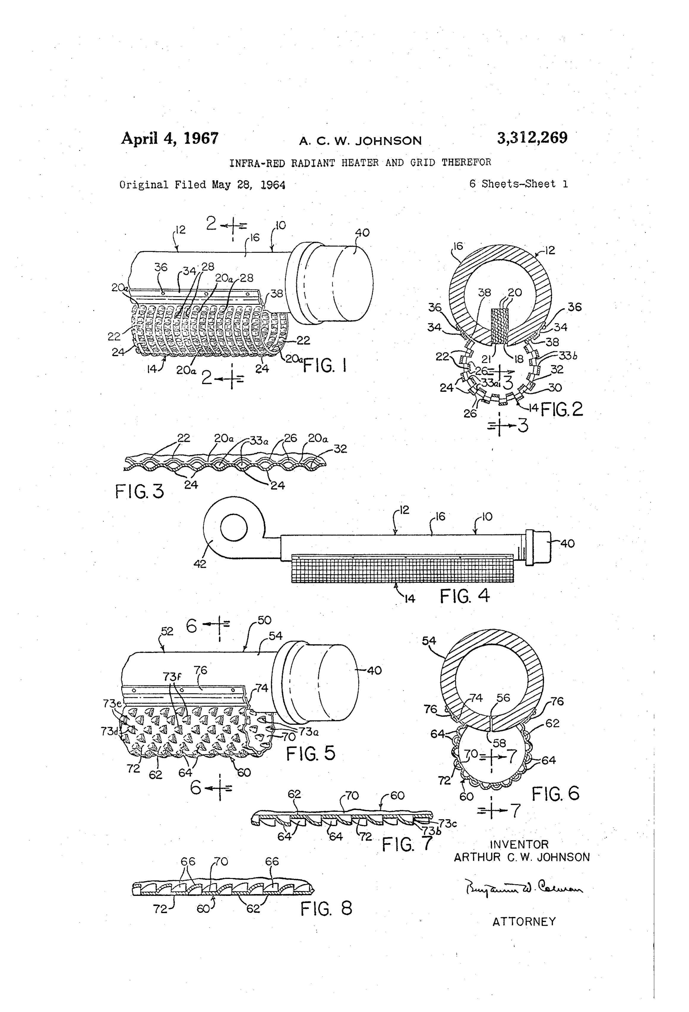
the heater operating successfully under such conditions FIGURE 1 is a perspective view of a portion of a gas without flashback or other difficulty due to the specific combination of burner and radiant grid design encom fired infra-red heater embodying the inventive con passed in the present invention. struction; - Where there is re-radiation onto the radiant grid or 0. FIGURE 2 is a vertical transverse sectional view where the heater is operating in a high temperature at taken substantially on the line 2-2 of FIGURE 1; mosphere, the fuel input necessary to provide a given FIGURE 3 is a vertical longitudinal sectional view radiant grid temperature is reduced. taken through the grid radiator substantially on the line The heater is not only simple and relatively inexpensive 3-3 of FIGURE 2;
to build, but because high output can be obtained from 75 FIGURE 4 is a side elevational view of the burner of
Page 9
FIGURE 1 coupled to a blower unit for feeding fuel gases enough air for its complete combustion, various commer to the burner at an elevated pressure; cial gas-air mixers being available to provide such a mix FIGURE 5 is a perspective view of a heater similar to ture.
that shown in FIGURE 1 showing a grid radiator having The burner 12 consists essentially of a conduit or dis opening shields of a slightly different form. 5 tribution tube for the fuel-air mixture and ports or orifices FIGURE 6 is a vertical transverse sectional view taken through which the combustible mixture passes to be substantially on the line 6-6 of FIGURE 5. burned. This conduit can be in the form of a cylindrical FIGURE 7 is a vertical longitudinal sectional view tube 16 as shown, or it can be fashioned in any other taken through the grid radiator substantially on the line Suitable form which will conduct or provide a passage way 7-7 of FIGURE 6. for the fuel from a source to the ports or orifices through
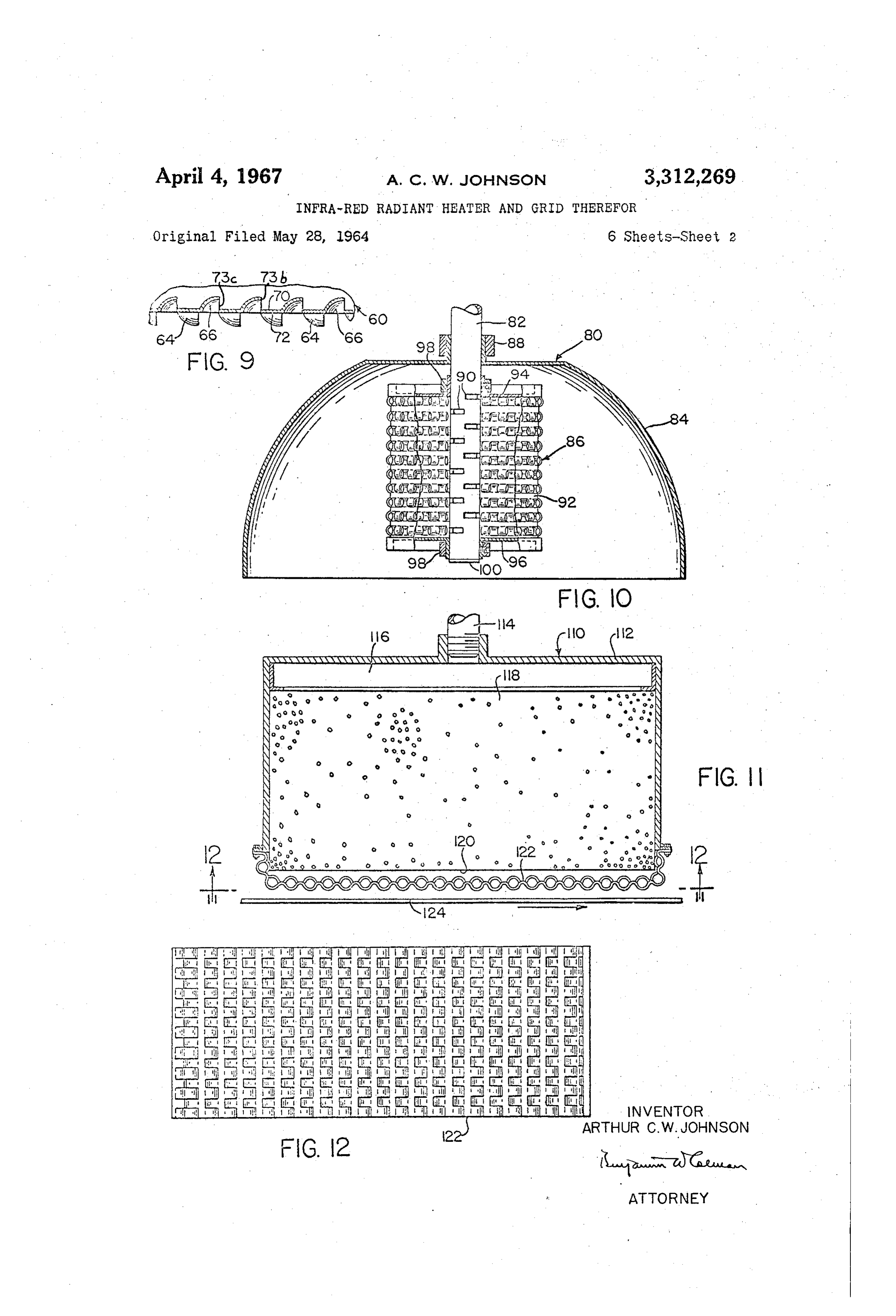
FIGURE 8 is a fragmentary sectional view of a grid the burner wall where it will be ignited and burn as a radiator having opening shields that are the inverse of flame, thus making available the latent heat contained those shown in FIGURES 5, 6 and 7. within such fuel. Upon combustion and generation of FIGURE 9 is a view similar to FIGURES 7 and 8 illus a flame, the heat generated is transferred by the flame trating a combination of outwardly and inwardly directed 5 radiation and movement of the hot combustion products opening shields in a grid radiator. to the body of the grid 14 upon which they impinge, the FIGURE 10 is a vertical sectional view, partially in flame gases passing over the inner and outer surfaces of elevation of a radiant heater and grid assembly arranged the radiant grid 14, heating these surfaces. in circular form. Several forms of a burner are illustrated in the draw FIGURE 11 is a vertical sectional view of another form 20 ings. It will be understood however that such forms are of the radiant heater and grid utilizing a porous ceramic merely indicative of some burners that can be utilized burner and the grid of this invention. in the invention, and that a number of other burner forms FIGURE 12 is a bottom plan view showing the grid sur can also be used. Basically a burner is a conduit for fuel face taken substantially on the line 12-12 of FIGURE 11. gases or other fuel forms that can be ignited at or adjacent FIGURE 13 is a perspective view showing a portion of 25 an outer surface of the conduit. Gases or other fuel can yet another form of the radiant heater utilizing the in be discharged from the conduit for combustion through ventive concept. small or large orifices, jets, porous ceramic, elongated FIGURE 14 is a vertical sectional view, partially in slots or slits, fine mesh screens of metal, glass cloth, glass elevation, of a battery of radiant burner and grid assem mat material, aluminum oxide woven fabrics, porous sin blies arranged for use in heating a continuously moving 30 tered metals and numerous other materials. Combustion planar sheet material. and flame generation takes place at the outer surface of FIGURE 15 is a top plan view taken substantially on these burners adjacent the fuel exists. the line 15-5 of FIGURE 14. In the form of the heater illustrated in FIGURES 1 and FIGURE 16 is a side elevational view, partially in verti 2, the conduit 16 is provided with a longitudinally extend cal section, of a battery of radiant burner and grid assem ing slot 18 that is filled with a laminate 20 of fine wire blies arranged for heating a cylindrical roll. screens relatively closely packed so as to form a tight FIGURE 17 is a slightly enlarged elevational view of mesh through which fuel gases pass to the outer surface the structure shown in FIGURE 16. 21 of the burner. The openings through which the gases FIGURE 18 is a view in side elevation of a section of emerge at the outer surface of the laminate 20 are very heater using another form of radiant grid and burner 40 small, much smaller than might be obtained by drilling orifice construction. or piercing the wall of the conduit 16. This wall as ilus FIGURE 19 is a view in end elevation of the heater of trated in the drawing is merely a pictorial representation FIGURE 18 but with the end covers of the burner tube and should not be construed as the preferred thickness and radiant grid omitted. of a conduit 16, whose wall may be much thinner or FIGURE 20 is a top plan view of a section of radiant 45 thicker depending upon the particular application for grid after it has been sheared and stamped but before which the heater 10 is designed. being bent into the form shown in FIGURES 18 and 19. The infra-red radiant grid 14 comprises a metallic body FIGURE 21 is a sectional view of the grid taken along 20a having alternating inwardly directed ribs or loops 22 the line 21-21 of FIGURE 20. and outwardly directed ribs or loops 24 formed by pushing FIGURE 22 is a side view of the grid shown in FIG 50 the metal of the body in opposite directions laterally of the URE 20. plane of the body and into ribs whose longitudinal ends are FIGURE 23 is a sectional view of the grid material integrally connected to the body 20 and whose lateral edges of FIGURE 20 but bent around another axis and taken 26 are raised above or depressed below the plane of the along the line 23-23 of FIGURE 24. body 20a So as to provide openings 28 through the body FIGURE 24 is a side view of a portion of the grid shown 55 of the grid which are formed by shearing of the metal in Section in FIGURE 23. when the ribs or loops 22 and 24 are formed so that no FIGURE 25 is a top plan view of a portion of the metal is removed from the grid to make the openings 28. burner grid of FIGURE 19. These openings pass the hot gases of the burner 12 through FIGURE 26 is a top plan view of one of the corrugated the body and laterally across the outer surface 30 of the elements of the grid of FIGURE 25. 60 inwardly directed ribs 22 and across the inner surface FIGURE 27 is a side view of the element of FIGURE 32 of the outwardly directed ribs 24, the gases also 26. passing through portions 33a and 33b which are defined FIGURE 28 is a view in side elevation of an aspirating by portions of the lateral edges 26 of ribs 22 and 24, re type heater with two inlets. spectively and co-operate with openings 28 to form FIGURE 29 is a vertical transverse sectional view 65 tortuous paths for the gases as they flow through the grid. through another embodiment of the invention. The hot gases also course over and across the inner sur FIGURE 30 is a vertical transverse sectional view face of the ribs 22 and the outer surface of the ribs. through another embodiment wherein fuel and combus 24 as they flow within and without the body 20a of the tion air are admitted through separate conduits and ports. grid 14. The ribs 22 and 24 at the same time provide flame shields at the openings 28, which they cover so that
As shown in the several views of the drawing, and with 70 there particular reference to FIGURES 1, 2, 3 and 4, the heater are no openings normal to the radiating surfaces or infra-red radiant burner and grid assembly 10 com of the grid and, so that a direct blast of air normal to the prises a burner 12 and a radiant grid 14 served with a surface of the grid is deflected by the ribs and caused to supply of gaseous-fuel. flow longitudinally of the grid, thus preventing flame snuff The gaseous or other fuel is ordinarily premixed with 75 out or quenching. The ribs 22 and 24 also have emitting
Page 10
surfaces at least equal in area to the openings 28 through of heat to them; and the emitting surface of the grid will the grid, and the projections of the portions 33a and 33b be substantially equal in radiant area to the projected area. defined by the lateral edges 26 of ribs 22 and 24 in a direc of the grid, maximizing the infra-red radiation emitting tion normal to the radiant surface of the grid do not area of the grid.
subtract from the emitting area. Therefore, the radiant 5 As shown in FIGURES 5 and 8, for example, the ribs grid has an emitting surface which is at least substan 64 and 66 may be arranged in parallel rows 73d with the tially equal in radiant area to the projected area of the ribs in each row opposite the spaces 73e in the adjacent grid. This maximizes the area emitting infra-red radia rows. The axes of elongation of the ribs (coincident with tion from the burner. The radiant grid operates to re lines 73f) all extend in the same direction in this particular radiate heat acquired from the burner back to the burner O grid, and all of the ribs are displaced to the same side of surface 21 and the surface of tube 16 within the compass the grid.
of the grid, where it is retransferred to incoming mixtures As in the case of grid 4, the grid 60 is provided with of gas and air and in so doing reinforces the heat generated lateral flanges 74. for engagement by conduit attached by the gas flame and intensifies combustion. The curved flanges 76 so that the grid radiator is fixed in place. The radiant grid also radiates heat inwardly, serving to further material for the grid 60 is the same as that for the grid heat adjoining and opposite walls thereof. 4. Although the ribs 64 and 66 are shown to be stag It will be understood that the grid can also be utilized in gered, they can also be arranged in alignment longi planar form as well as in circular form, and can be em tudinally and transversely if preferred or required. ployed in rectangular arrangements, or in a combination The radiant heater of this invention lends itself advan of straight and curved configurations, the illustrated forms 20 tageously to applications for unit heaters in single units being merely representative to certain particular embodi or in multiples. A representative embodiment of a com ments of the inventive construction. The grid 4 is pact unit heater is that illustrated in FIGURE 10, in secured to the burner in any suitable manner and by any which a radiant heater 80 comprises a burner conduit 82 suitable means, the embodiments in FIGURES 1, 2 and 4 supporting a heat reflector 84 and a radiant grid assembly illustrating longitudinally extending flanges 34 secured to 86. The reflector 84 is secured upon the conduit 82 by the conduit 6 by rivets 36, or screws, clips, or other suit any suitable means, a ferrule 88 being shown. The con able fasteners, one edge of the flange over-lying a lateral duit is provided with ports or slits 90 for discharge of edge 38 of the radiant grid or radiator at each side thereof. fuel gases, ignition taking place at the outer areas of the A suitable structure for securing the radiant grid is shown slits, the hot gases being directed radially from the burner in FIGURES 18 and 19, this structure permitting free 30 for impingement upon the inner surface of the grid 92. expansion and contraction of the lengthwise dimension The radiant grid assembly 85 comprises the grid 92, end of the grid. plates 94, 96 closing off the open ends of grid 92 which The burner 16 is normally provided with a cap 40 over is in substantially circular form, and ferrules or collars its end so as to prevent free escape of the fuel gases passed 98 that secure the end plates to the burner conduit 82. through it and the radiant grid is normally provided with A conduit cap or plug 100 closes the burner against free closures (not shown) at its ends to prevent the escape of escape of fuel gases except through the slits 90. The grid hot combustion gases. construction is substantially the same as that of grid 14 In FIGURE 4 there is illustrated a radiant burner 10 above described.
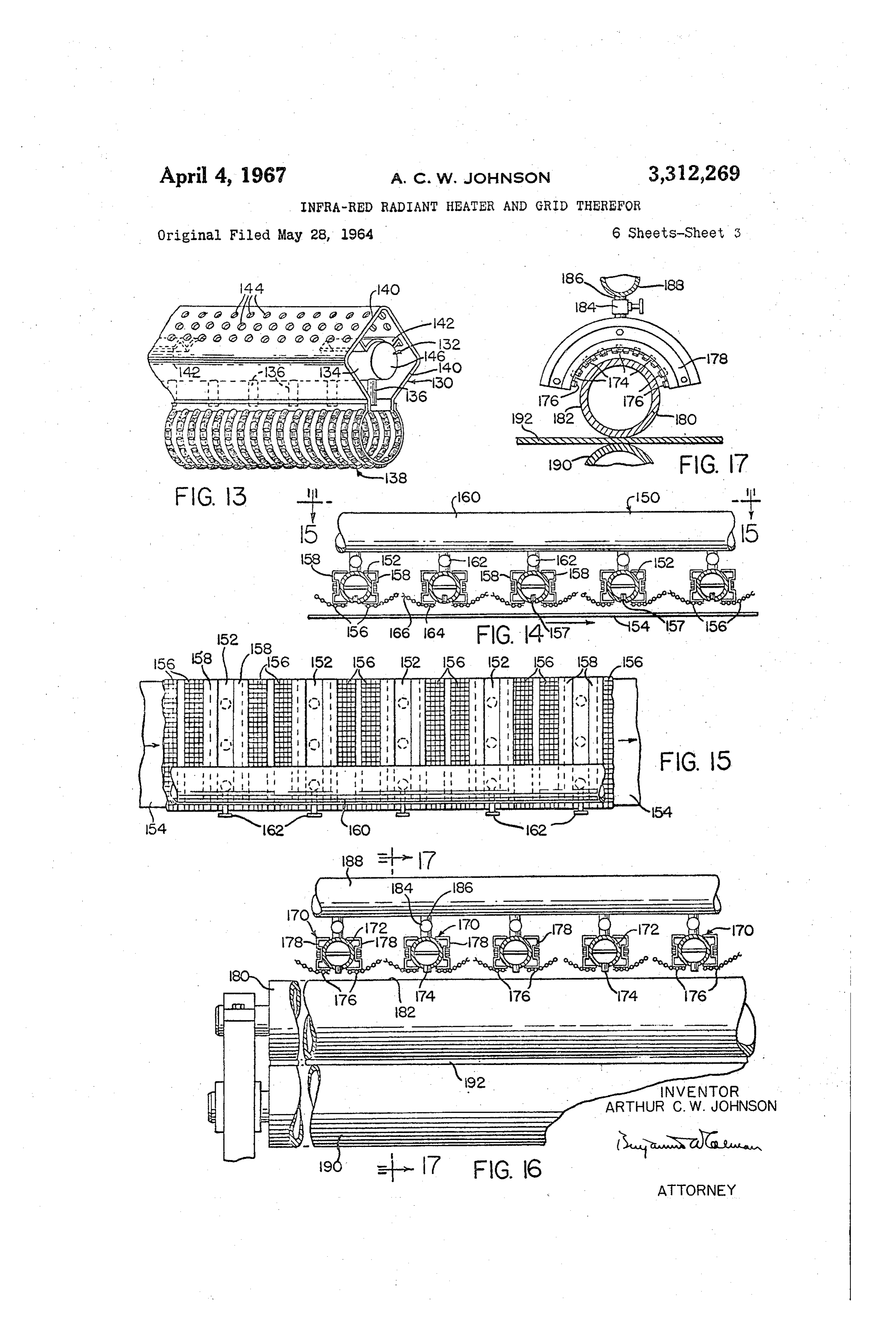
charged with fuel gases by a blower unit 42 connected An illustration of a representative example of a radiant to the burner 12 at its inlet end. This structure permits of 40 heater employing a porous ceramic burner is that shown pre-mixing fuel gases and air and of discharge of such in FIGURE 11, in which the heater 110 comprises an premixes at higher than normal pressures so as to increase outer housing 112, a conduit 14 passing fuel gases to the the volume of gases ignited at the burner surface and housing chamber 16, a porous ceramic block 18 through thus elevate the operating temperature of the heater. which the fuel gases are passed to the flame surface 20 A slightly modified radiant heater 50 is illustrated in where these gases are ignited and burn, and a grid 22 FIGURES 5, 6, 7, 8 and 9. In this structure, the burner 45 of substantially the same construction as grids 14 and 92 52 is substantially the same as the burner 12 except that although arranged in planar instead of circular form. instead of the closely packed screens 20, the conduit 54 The grid 122 is mounted so as to lie flat against the sur is provided with small orifices 56 through which the fuel face 20 of the block 118 or slightly spaced therefrom gases are discharged for ignition and combustion at the 50 as in FIGURE 11. The radiant heater 10 can be utilized conduit surface 58. The radiator grid 60 is composed as a single unit or in a battery of such units. The radiant of a sheet metal body 62 and outwardly projecting ribs 64 heater 110 is adapted to heat stationary planar surfaces (FIGURES 5, 6 and 7), or inwardly projecting ribs 66 or continuously moving planar sheet material 424. (FIGURE 8), or a combination of inwardly directed ribs The radiant heater 130, FIGURE 13, utilizes a burner 66 and outwardly directed ribs 64 (FIGURE 9) which 55 132 having a fuel gas conduit 134 and jets 136 projecting define channels through which the hot combustion gases from the conduit at spaced intervals and from which will emerge after impingement upon the inner surface 70 issue flames and gases that impinge upon the grid 138, of of the radiator or radiant grid 60. The hot combustion Substantially the same construction as that of grids 14 and gases wash the inner and outer surfaces 70 and 72 of the 92, Secured at its lateral edges to the opposing side walls sheet metal body 62 as well as the inner and outer surfaces 60 140 by spaced members 142 secured by welding or other of the ribs 64 or 66, as the case may be. Thus, heat is suitable means to the conduit body and to the side walls. transmitted to substantially the entire surface on both An air supply filter screen can be made of screen wire or sides of the radiator grid 60 effecting re-radiation to the other conventional screening, or it can be made in the burner 52 and amplification of heat generation as well as side walls 140 by perforating the walls with openings 144 radiation outwardly to bodies or surfaces to be heated by through which air can be drawn to serve and provide the unit 50. As in the case of grid 4, displacement of some or all of the air for the combustion of fuel at the jets ribs 64 and/or 66 forms openings 73a in the grid; and the 136. A closure or cap 146 is applied to the end of the lateral edges 73b of the ribs define ports 73c which com burner 132. Although grid 138 is shown open at its ends, municate with openings 73a and co-operate with them to in some instances it may be desirable to close the ends in form tortuous paths through the grid for the combustion which case a solid plate or a closure formed of the grid products. The ribs overlie openings 73a, and the projec material 138 can be attached in any suitable manner. tions of ports 73c normal to the radiant surface lie in Another arrangement embodying the inventive con teriorly of the lateral edges 73b of the ribs so there are no openings through the grid normal to its radiant struction for heating continuously moving or flowing sheet surface. Therefore the hot gases will course over the material is illustrated in FIGURES 14 and 15, in which - ribs as they exit through the grid, maximizing the transfer each radiant heater unit 150 comprises a burner 152, sub
Page 11
9 O stantially the same as burner 12 of FIGURE 2 or the its inner surface. The roll 180 and its complementary burner of FIGURE 19 so that the flame and combustion roll 190, roll the material 192 therebetween under heat gases are directed toward the sheet material 154 to be and pressure.
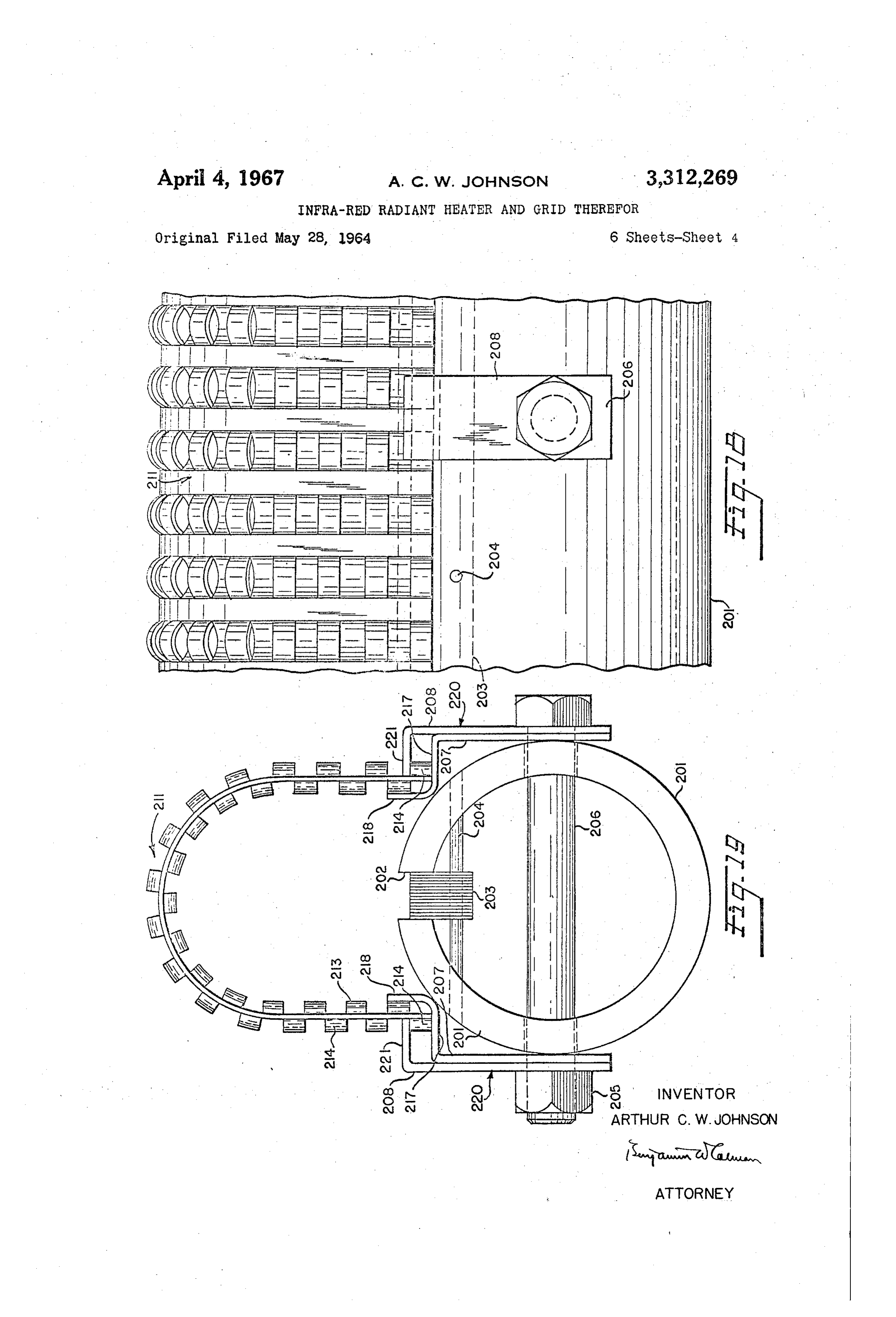
heated, grid radiator sheets 156 projecting laterally adja In the embodiment of FIGURES 18 and 19 a burner cent the jets 157 and secured to bracket members 158 5 tube 20 is provided with a longitudinal slot 202 which by fasteners supported by the burners 52, and a conduit receives an elongated orifice grid 203, shown in detail in 160 supplying fuel gases to the burners 152, the supply FIGURES 25 to 27. A series of pins 204 passing through to each burner being controlled by a valve 162. the tube 201 and the grid 203 holds the grid in place in In the radiant heater illustrated in FIGURES 14 and the slot. The grid is also secured by the clamping action 15, the grid sheets 156 have a first planar portion 164 ar 0 of the sides of the slot 202 in the burner tube 201 when ranged parallel to the plane of sheet material 154 and a a nut 205 is tightened on a bolt 206 passing diametrically second planar portion 66 directed upwardly at an angle through the tube below the slot 202. A series of such to the plane of portion 164. Convective impingement of bolts 206 along the length of the burner tube 201 also the flame gases issuing from burners 152 upon the con clamp pairs of inner and outer mounting brackets 207 tinuously moving sheet material 154 is directed back to 15 and 208 which removably secure a radiant grid 211 in grid portions 164 from which they are re-radiated to the place over the longitudinal orifice grid 203 in a manner sheet material and then to and through the grid portion to be described.
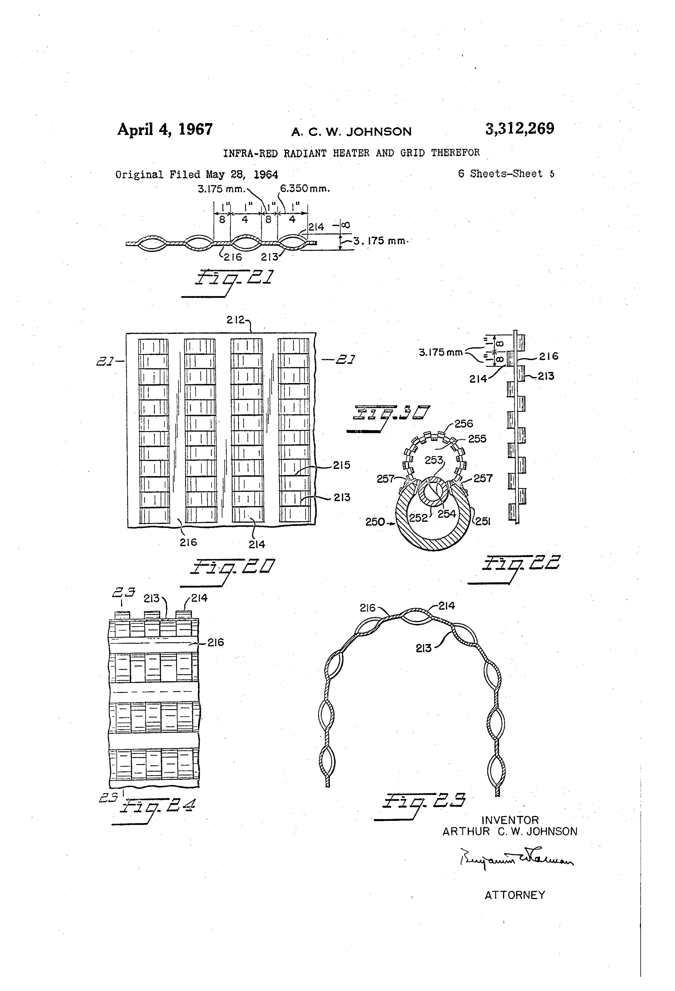
166 operating as a secondary radiator or reflector, passing The radiant grid 211 is formed from a sheet of metal away as waste gases between the grids of the heater units 212 shown in FIGURES 20 to 22. The sheet of metal 150. 20 212 has spaced rows of alternately downwardly depressed A most difficult heating problem is one which involves and upwardly extending rounded projections or corru or requires the heating of industrial rolls or strip having gated ribs 213 and 214 on opposite sides of shear lines a highly polished and reflective surface. Such rolls are 215 formed in the sheet 212 when the projections 213 and used for polishing and rolling of metals, paper, plastics 214 are formed. The metal forming the projections or or other sheet material passed in a continuous flowing 25 ribs is slightly stretched and consequently a little thinner fashion through and between a pair of such rolls. Direct than the remaining flat portions 216 between the rows of radiation alone limits the ability to efficiently heat such projections.
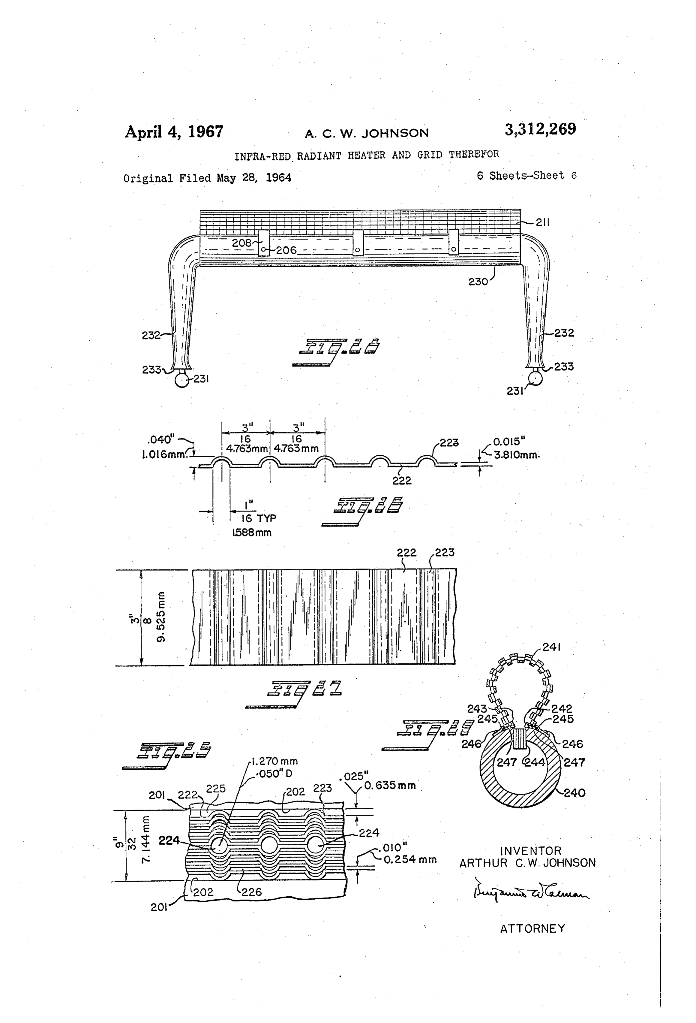
rolls or sheets. It is very desirable in such a situation to The grid may be bent along one axis of a U-shape such apply and obtain a maximum convective effect. This can 30 as shown in FIGURES 23 and 24 or it may be bent along be accomplished by placing the work between primary a second axis to the shape shown in FIGURE 19. When and secondary grids, thus obtaining maximum convective bent as in FIGURE 19 the radiant grid securing means action prior to secondary radiation. In FIGURES 16 and shown in FIGURES 18 and 19 may be used. As shown 17 is illustrated a radiant heater construction which can in FIGURE 19 each inner mounting bracket 207 has an more efficiently heat the highly polished surface of a 35 inwardly extending portion 217 which terminates in an roll by utilizing a burner and the grid structure of this upwardly extending portion 218. At least the bottom invention. row of depressed ribs rests against the outer side of the The radiant heater unit 170 comprises a burner conduit bracket portion 218. The outer mounting bracket 208 172 having flame jets 174 issuing from the conduit, and terminates at its upper end in an inwardly directed leg a pair of grids 176 disposed on either side of the jets and 40 220 that engages the upper edges of the lowermost row secured to the burner conduit 172 by members 178. The of raised ribs 214. Each edge of the radiant grid 211 is burner conduit 172 encircles a portion of the circumfer thus gripped by a pair of inner and outer mounting brack ets 207 and 208 at suitably spaced points along the length ence of the roll 180 and the flame and flame gases from of the grid. The grip is sufficiently loose to permit the jets 74 impinge directly upon the surface 182 of the roll, from which surface they are reflected or deflected lengthwise expansion and contraction of the grid, yet se to the grid structures 176 which radiate heat back to the 45 cures the grid against transverse displacement. Removal and replacement of the radiant grid is by loosening the roll surface 182, the gases finally passing through and be nuts 205 on the bolts 206 until all the mounting brackets tween adjacent grid structures. In this arrangement pri 208 are loose and can be disengaged from the grid. The mary radiation is initially generated within and by the old grid is removed and a new one inserted. To prevent flame gases which strike directly upon the roll surface, while simultaneously imparting heat energy by convec 50 gas leaks where the bolts 206 pass through the burner tion, then bouncing off the roll surface to the adjacent tube 201 suitable gaskets, not shown, surround the bolts radiant grids 176 forming the secondary radiators. In 267. 206 between the tube 201 and the inner mounting brackets order to avoid the cutting and piecing which would be Alternatively, the radiant grid may be removed and necessary to bend the grids 176 from a flat grid to one replaced by sliding it lengthwise through the mounting having the double curvature of FIGURES 16 and 17, the 55 to brackets, the grips of the brackets being sufficiently loose grid could be bent with only a single curvature to encircle permit this. In such case of course the nut 205 and the roll 180, in which case the grid sections of FIGURE bolt 206 need not be loosened. Also, each pair of mount 16 appear straight rather than bent upwardly at their outer ing brackets 207 and 208 may be spot welded together. portions. A battery or multiples of the heater unit 170 One form of an elongated orifice grid which has been found satisfactory is that referred to by reference numeral are arranged substantially in parallel relation longitudi 60 203, nally of and peripherally about a portion of the roll 180. a portion being shown in enlarged detail in FIG To control the flow of fuel to the burner conduit 172 a. URES.25, 26 and 27. It is composed of a series of sheets valve 184 is disposed in conduit 186 leading from the of metal having spaced corrugations. Each sheet 222 fuel supply conduit 188 that serves all of the heater units has a series of parallel spaced corrugations 223 projecting 170. 65 upwardly (in FIGURE 26) in the same direction. The Although the circular heater units 170 are disposed grid is formed by placing a number of sheets 222 against transversely of the roll, it will be understood that straight each other with the corrugations 223 nested in each other heater units can be disposed longitudinally and radially as shown in FIGURE 25. This makes the individual of the roll to perform the same function of heating the sheets closer together than if the corrugations were not roll surface 182. The structure illustrated in FIGURES 70 so nested. For example in the grid of FIGURE 25 the 16 and 17 discloses a heater unit designed to heat the outer sheets 222 are spaced 0.01 inch (0.254 mm.) apart where surface 182 of the roll 180. The heater unit, when as if the corrugations were not nested the spacing would inverted so that the jets are disposed radially outwardly be 0.025 inch (0.625 mm.).
and the grids 176 are outwardly adjacent the jets, can Also, in the orifice grid of FIGURE 25 half of the also be used internally of the roll to heat the roll from 75 sheets 222 face in one direction, then at the centerline of
Page 12
the grid the sheets are reversed and the remaining ones burner tube is supplied with a premixture of air and fuel face in the other direction. The two central sheets 222 under a blower or other pressure as in FIGURE 4, etc. both have their corrugations facing outwardly. Thus Consequently wider longitudinal slots and orifice grids their flat portions are in full contact and the paired out along the length of the burner tube 236 are required than wardly facing corrugations form a series of spaced Sub 5 is the case for example for the heater of FIGURES 18 stantially circular orifices. and 19. The wider width of the orifice grids is attained As described in FIGURE 19 the corrugated sheets 222 by increasing the number of corrugated sheets 222 of forming the orifice grid 203 are clamped between the Walls FIGURE 26 to fill the wider slot. of the slot 202 in the burner tube 201. The entire as Because of the relatively low pressure of the mixture sembly results in groups of orifices of different sizes. For 0. of fuel and aspirated air in the burner tube 230 two ven example, in the grid of FIGURE 25 wherein the sheets turi tubes 232 are used to feed the burner tube at its two 222 are 0.015 inch (0.381 mm.) thick the substantially ends, to reduce the effect of pressure drop of the mixture circular orifices 224 along the centerline are 0.050 inch within the burner tube at points spaced away from the (1.270 mm.) in diameter. The elongated orifices 225 venturi tubes 232. Where the burner tube 230 is suffi between the outermost sheets 222 and the edge of the ciently long from end to end, it is within the province of slot are 0.025 inch (0.635 mm.) wide and about three the invention to add aspirating venturi tubes 232 along sixteenths of an inch (4.763 mm.) long. The narrowest its length so that the fuel air mixture is supplied at a orifices 226 between adjoining nested sheets 222 are 0.010 substantially equal pressure along the length of the burner inch (0.254 mm.) wide and three sixteenths of an inch orifice grid.
(4.763 mm.) wide. All the orifices are three eighths of 20 Also, in an aspirated air heater as illustrated in FIG an inch (9.525 mm.) deep, this being the width of the URE 28 the downwardly depressed and raised projections sheets 222. 213 and 214 of the radiant grid 21 shown in FIGURES In the grid illustrated these dimensions result in a large 18 to 22 are larger than the example shown in these FIG total orifice area but with a high ratio of individual orifice URES 18 to 22 in order to provide larger openings at length (or depth) to individual orifice cross-sectional area the shear lines 215 to reduce internal pressure of the hot to permit the flow of a large volume of fuel and combus combustion gases between the radiant grid and the orifice tion air mixture to provide the high output that must be grid and consequently reduce the pressure required to delivered by the burner grid and still prevent flashback force the mixture of fuel and combustion air through into the burner tube 281. As mentioned before, the ten the burner orifice grid. The radiant grid 211 of FIGURE dency to backfire is enhanced because the mixture passing 30 28 is preferably secured to the burner tube 230 by the through the orifice grid is much more combustible than structure shown in FIGURES 18 and 19, including the if only fuel were passing through the grid, and it is also bolts 205 and inner and outer mounting brackets 207 and much greater in volume. The backfire tendency is also 208 of FIGURES 18 and 19, only the outer mounting increased because of the very high temperature in the brackets 208, being visible in FIGURE 28. combustion space between the orifice grid 203 and the In FIGURE 29 is shown a construction wherein the radiant grid 211 which is in close proximity to the orifice exposure of the burner tube 240 to the heat of the hot grid. While they are narrow or of small cross-sectional flame and combustion products within the radiant grid area with respect to their depth to prevent backfire of the 241 is reduced by mounting the longitudinal edges 242 combustible mixture, the orifices are of sufficient number and 243 of the radiant grid closely adjacent the sides of to supply the required amount of combustible mixture an orifice grid 244, which in the embodiment shown is and permit a velocity through the burner tube 20A high the ribbon type orifice grid shown in FIGURES 19 and enough to keep it cool and well below the ignition tem 25, although it is to be understood that this embodiment perature of the mixture. The aforementioned dimensions is applicable to any burner construction where the burner of the orifice grid 203 are substantially pertinent to one orifices are in one longitudinal area or zone of the burner where the radiant grid 211 of FIGURE 19 has a curvature tube 249.
with a radius of approximately 0.75 inch (19.05 mm.) 45 In FIGURE 29 the radiant grid 241 which is otherwise and a total height from the inwardly extending portions similar to that shown in FIGURES 1, 2, 18 and 19 is shown of inner mounting brackets 207 to the top of the grid of secured to the burner tube 240 by longitudinally extend approximately 1.50 inches (38.10 mm.). The width of ing flanges 245 affixed to the burner tube as by rivets the orifice grid 203 as determined by the width of the slot 246, one edge of each flange 245 overlying a projecting 202 is nine thirty-seconds of an inch (7.144 mm.). Greater 50 lateral edge 247 of the radiant grid 24 at each side volumetric capacity of the orifice grid 203 for the same thereof, in the manner shown in FEGURES 1, 2, 5 and internal pressure within burner tube 20 is attained by 6. As in those figures, the flanges 245 permit longitudinal increasing the width of the burner tube slot 202 and in expansion and contraction of the radiant grid. creasing the number of corrugated sheets 222 to fill the The reduction of the exposure of the surface of the slot. The sheets 222 forming the burner grid orifices are 55 burner tube 240 to the hot flame and hot combustion preferably made of high temperature and corrosion re products within the radiant grid 241 as compared to the sistant steel. exposure in FIGURES 1, 2, 5, 6, 18 and 19 etc. results Dimensions of the projections and depressions of the in a substantial increase in the efficiency of the infra-red radiant grid sheet 212, before being curved as in FIG radiant heater and reduces the possibility of backfire URE 19 to form the radiant grid 211, are shown in FIG 60 through the orifice grid 244 into the burner tube 249. URES 21 and 22. It is formed of 26 gauge (0.45 mm. This is particularly important in heater installations which thick) Inconel. result in high ambient temperatures around the radiant While the preceding description, with the exception of grid and burner tube.
that of FIGURE 13, has pertained to a construction where in a mixture of fuel and combustion air is fed under 65 in Another FIGURE embodiment of my invention is illustrated 30, wherein the fuel and combustion air are pressure to a burner tube such as 201 of FIGURES 1, 4 not premixed before admission into the combustion space and 19, it is equally pertinent to a construction as illus within the radiant grid that encloses the combustion space, trated in FIGURE 28 where the burner tube 230 is fed with a mixture of fuel from fuel supply lines 231 which but are admitted separately under pressure into the com discharge fuel under pressure into a number of spaced bustion space from the burner tube which includes sep venturi tubes 232 which aspirate all required combustion arate conduits for the fuel and for the combustion air, dis air through adjustable aspirating openings 233 of well charging combustion air through one set of orifices, and known type at the entrances of the venturi tubes. In fuel, such as gas or any of the previously mentioned fuels Such constructions the internal pressure of the air and through another set of orifices. In this embodiment the fuel within the burner tube 230 is less than when the 75 possibility of backfire into the burner tube is completely
Page 13
13 E4.
avoided, because there is not a combustible mixture either area and number of grid openings be such that the hot in the fuel conduit or the air conduit. combustion gases flow freely therethrough, while main As shown in FIGURE 30 the burner tube generally taining an effective distribution of such gases throughout designated by the reference number 250 comprises an the operating and functioning area of the burner orifice external combustion air pipe 251 having a co-aligned grid and the radiant grid.
fuel pipe 252 arranged longitudinal along the external Although not deemed essential, it is preferred that the combustion air pipe 251 at a peripheral portion thereof, radiant grid openings be substantially of the same size in and affixed at this peripheral portion as by welding or order that the heat of the hot combustion products be the like. The combustion air pipe 251 has a longitudinal relatively uniformly distributed across the surface of the radiant grid body which will then produce a relatively slot to receive the fuel pipe 252, or as is obvious, the fuel O uniform pipe 252 may be U or otherwise shaped and welded to temperature heating surface. Where hot spots the pipe 25 with its common wall 253 perforated as by of higher temperature occur, decomposition and over orifices 254 for the admission of gaseous or other fuel heating of such localized area hasten and accelerate the into the combustion space 255 within the radiant grid destruction of the radiant grid. 256. Adjacent and alongside the outsides of the junc Recognizing these factors, persons skilled in the art tures of the fuel pipe 252 and the combustion air pipe to which the invention pertains will understand that the 251, the combustion air pipe 251 has a longitudinal series radiant grid openings are variable depending upon the of orifices 257 for admission of combustion air from the particular application for which the heater is required. combustion air pipe 251 to the combustion space 255 The volume and flow rate of fuel gases to maintain within the radiant grid 256. These orifices 257 may be, 20 required temperatures will play a leading role in the but are not necessarily in the same transverse planes as determination of radiant grid opening areas. Such re the orifices 254 for the fuel from the fuel pipe 252. quired areas may be provided by increasing or decreasing In FIGURE 30 the radiant grid 256 is shown attached to the number of openings through the grid body, with the the burner tube 251 in the same manner as the embod understanding that a fewer number of openings of sub iments of FIGURES 1, 2, 5 and 6 and the description 25. stantially excessive area can result in a material loss of heat and energy through too rapid dissipation of the hot
In the embodiment of FIGURE 30, not only is the combustion gases, and that an insufficient number of possibility of backfire into the burner tube eliminated grid openings may result in inefficient operation of the because there is no combustible mixture of air and fuel heater.
in the burner tube 250, but also the temperature of the 30. Another feature of the radiant grid structures of this fuel pipe 252 is reduced by the cooling effect of the com invention is that in the forms illustrated the laterally bustion air in the combustion air pipe 251 which almost deformed projections or shields, whether inwardly and/or surrounds the fuel pipe 252. outwardly directed, are formed from the grid body with The temperatures for which the radiant heater has 35 out loss of metal. That is, no metal is removed in the been designed, when natural gas is used without forced production of the grid structure and in fact the surface air, is in the range of from about 1000 F. to about area is increased. The laterally deformed opening shields 2100 F. For heaters with forced air-gas premixes the or projections may be arranged in staggered patterns or radiant heaters are designed to operate in the range of in aligned patterns, as described and illustrated, or in from about 1000 F. to about 2700 F. other preferred or required patterns depending upon the The heaters herein disclosed can be used without re 40 application for which the heater is designed. The planes flectors; but, as is well known in the art, reflectors are of the radiant grid openings, formed along the shear often desirable to focus the heat radiated from the radiant lines defining the ends of the shields or projections are grids, reducing the heat dissipation to bodies or surfaces substantially normal to the plane of the grid body. which it is not desired or required to heat and confining It will further be recognized that the radiant grid the heat to surfaces and bodies for which the installation 45 structures of this invention forms a combustion cham was designed. ber with the burner tube whereby the flame and hot The radiant grids herein disclosed can take any of the gases of combustion flow in various paths and courses several forms shown and described although the form between the burner orifice grid and the radiant grid struc shown in FIGURES 20 to 22 wherein the depressed and ture. The flow of hot combustion gases and the radiant raised projections 213 and 214 are substantially circular 50 heat from the flame are the means by which the radiant in cross-section is preferred. These grid structures in each grid is heated.
instance embody a grid body having openings therethrough The invention may be embodied in other specific defined by shear lines which in turn define shields for the forms without departing from the spirit or essential openings formed laterally outwardly and/or inwardly characteristics thereof. The present embodiments are of the grid body, the opening being disposed in planes sub 55 therefore to be considered in all respects as illustrative stantially normal to the plane of the grid body. They and not restrictive, the scope of the invention being indi each contain a relatively large number of shielded open cated by the appended claims rather than by the fore ings, and these openings are of a total area that will pass going description, and all changes which come within the a relatively large volume of hot gases therethrough di meaning and range of equivalency of the claims are there recting them along the surface of the radiant grid in a 60 fore intended to be embraced therein. direction parallel to the axes of the curved projections I claim:
and/or depressions. Where the grid is curved as in FIG 1. In an infra-red radiant heater of the combustion URES 6 and 23 the hot gases are discharged parallel to type:
the axis of the radiant grid as well as to the axes of the (a) means forming a walled fuel-air mixture distri projections. If the area of the grid openings is reduced 65 bution chamber for a combustible mixture of fuel individually and/or collectively to a degree or magni and air;
tude such that the flow of gases of combustion, which (b) said distribution chamber having means for dis carry the heat, is substantially impeded in their passage tributing the fuel-air mixture to a combustion zone through the radiant grid body, then in such event the flow adjacent said distribution chamber so as to main of combustion gases will be choked off due to insufficient 70 tain the region of said wall adjacent said com port area, causing low gas combustion and a drop in bustion zone at a non-incandescent temperature; temperature output. In a constant pressure system such (c) a deterioration resistant, apertured radiant grid as is here described for the radiant heater of this inven tion, the radiant grid port area is related directly to the which is the primary burner component adapted to efficiency of the heater. If is therefore essential that the 75 be heated to incandescence by the combustion of
Page 14
the fuel-air mixture in the combustion. Zone ad (a) and the wall of said supply chamber having a slot jacent said distribution chamber; therethrough snugly gripping said laminate. (d) said grid overlying the region of the distribution 5. The radiant heater of claim , wherein the ribs of chamber in which said combustible mixture distri the radiant grid have a uniform and arcuate cross-section buting means are provided and the combustion Zone 5 at configuration, whereby there are generally normal ports for the mixture issuing from said means; defined by said ribs at both lateral edges of each of said (e) said grid further surmounting said combustion Zone ribs, and wherein the ribs are arranged in parallel spaced so that said combustion zone lies substantially within apart rows, successive ribs in each of said rows being dis the compass of said grid and said grid provides out placed on opposite sides of the grid and the ribs being So lets for combustion products generated in said com 10 oriented that the axes of elongation of all said ribs lie in bustion zone; parallel planes.
(f) the region of said grid through which said com 6. The heater of claim 1, together with means for bustion production products pass from said combus Supplying the combustible fuel-air mixture to the distri tion zone being substantially coextensive in length bution tube, which comprise:
with said combustion zone so that said radiant grid 5 (a) plural venturi tubes spaced along and communicat is heated by combustion of the fuel-air mixture in ing with said distribution tube at their outlet ends; said combustion zone and the radiant energy and (b) a fuel supply line communicating with the inlet sensible heat in the combustion gases formed in ends of said venturi tubes for supplying a fluid fuel said combustion zone are substantially uniformly thereto, and imparted to said radiant grid; 20 (c) means forming atmospheric air aspirating openings (g) said radiant grid being fabricated of heat re at the inlet ends of said venturi tubes; sistant material having imperforate ribs displaced (d) whereby the fuel supplied to each said venturi tube therefrom to provide openings through the grid, will induce air therein and become mixed with said the outer surfaces of said ribs extending generally air as it flows through the venturi tube to form the parallel with the plane of the grid and serving to 25 combustible fuel-air mixture for the burner. defect laterally and away therefrom any air cur 7. In an infra-red radiant heater of the combustion rents moving substantially normal to said plane, said type:
ribs being so located that there are no openings (a) means forming a walled fuel-air mixture distribu through the grid normal to the radiant surface where tion chamber for a combustible mixture of fuel and by Said radiant grid has an emitting Surface which is 30 alr;
Substantially equal in radiant area to the projected (b) said distribution chamber having means for dis area of the grid so as to maximize the area ennitting tributing the fuel-air mixture to a combustion Zone infra-red radiation from the burner; adjacent said distribution chamber so as to maintain (h) the lateral edges of said ribs defining ports which the region of said wall adjacent said combustion Zone communicate with the aforementioned openings at a non-incandescent temperature; through the grid to form tortuous paths for the flow (c) a deterioration resistant, apertured radiant grid of combustion products through said grid, the edges which is the primary burner component adapted to of said ribs being so located that the projected areas be heated to incandescence by the combustion of of said ports normal to the radiant surface are in the fuel-air mixture in the combustion zone adjacent teriorly of said ribs; 40 said distribution chamber;
(i) whereby the hot combustion gases formed in said (d) said grid being bent around an axis parallel to the combustion Zone will course over the ribs of said grid major dimension of the distribution chamber and as they are exhausted from said combustion Zone overlying the region of the distribution chamber in through said grid to maximize the transfer of heat which said combustible mixture distributing means from said gases to said grid. are provided and the combustion zone for the mix 2. The infra-red radiant heater structure of claim 1 ture issuing from said means; wherein said combustible mixture distribution means com (e) said grid further surmounting said combustion Zone prises a series of elongated sheets having spaced parallel so that said combustion zone lies substantially with corrugations, in the compass of said grid and said grid provides (a) the corrugations of at least some adjoining sheets 50 outlets for combustion products generated in said being nested in each other, combustion Zone;
(b) and the wall of said supply chamber having a slot (f) the region of said grid through which said com therethrough to snugly receive a group of said cor bustion products pass from said combustion Zone be rugated sheets. ing substantially coextensive in length with said com 3. The infra-red radiant heater structure of claim 1 bustion zone so that said radiant grid is heated by wherein said combustible mixture distribution means com combustion of the fuel-air mixture in said combus prises a series of at least four elongated sheets having tion zone and the radiant energy and sensible heat spaced parallel substantially semi-circular corrugations, in the combustion gases formed in said combustion (a) the corrugations of the central pair of sheets fac Zone are substantially uniformly imparted to said ing outwardly in opposite directions in the same 60 radiant grid;
transverse planes whereby the flat portions of the (g) said radiant grid being fabricated of heat resistant sheets abut each other and the paired corrugations material having imperforate ribs displaced therefrom form substantially circular passageways, to provide openings through the grid, the outer Sur (b) the corrugations of the remaining sheets on either faces of said ribs extending generally parallel with side of the central pair being nested in each other 65 the plane of the grid and serving to deflect laterally to provide narrow substantially rectangular passage and away therefrom any air currents moving Sub Ways, stantially normal to said plane, said ribs being SO (c) and the wall of said supply chamber having a located that there are no openings through the grid slot to snugly receive a group of said corrulated 70 normal to the radiant surface whereby said radiant grid has an emitting surface which is substantially sheets. equal in radiant area to the projected area of the 4. The infra-red radiant heater of claim wherein said grid so as to maximize the area emitting infra-red combustible mixture distribution means comprises a lami radiation from the burner; nate of closely packed fine wire screens all perpendicular (h) the lateral edges of said ribs defining ports which to the wall of said supply chamber, 75 gommunicate with the aforementioned openings
Page 15
through the grid to form tortuous paths for the flow through the grid to from tortuous paths for the flow of combustion products through said grid, the edges of combustion products through said grid, the edges of said ribs being so located that the projected areas of said ribs being so located that the projected areas of said ports normal to the radiant surface are inter- of said ports normal to the radiant surface are in iorly of said ribs; 5 teriorly of said ribs;
(i) whereby the hot combustion gases formed in said (i) whereby the hot combustion gases formed in said combustion zone will course over the ribs of said grid combustion zone will course cover the ribs of said as they are exhausted from said combustion zone grid as they are exhausted from said combustion through said grid to maximize the transfer of heat zone through said grid to maximize the transfer of from said gases to said grid. IO heat from said gases to said grid; 8. The infra-red radiant heater of claim 7 wherein the (j) a series of bolts passing substantially diametrically ribs of the radiant grid are all parallel to the axis around through said distribution tube wall and perpendicular which the radiant grid is bent, whereby the combustion to said burner orifice grid to compress said burner gases issuing from the ports defined by the lateral edges orifice grid between the edges of the slot in the dis of the ribs flow axially over the adjoining surfaces of 15 tribution tube wall; and the grid. (k) fastening means carried by said series of bolts 9. The infra-red radiant heater of claim 7, wherein the securing the radiant grid to the distribution tube sub ribs of the radiant grid are all perpendicular to the axis stantially at the edges of the radiant grid. around which the radiant grid is bent, whereby the com- 11. In an infra-red radiant heater of the combustion bustion gases issuing from the ports defined by the lateral 20 type:
edges of the ribs flow tangentially over adjoining surfaces (a) means forming a walled fuel-air mixture distribu of the grid. tion chamber for a combustible mixture of fuel and 10. In an infra-red radiant heater of the combustion air;
type: (b) said distribution chamber having means for dis (a) means forming a walled fuel-air mixture distribu- 25 tributing the fuel-air mixture to a combustion Zone tion chamber for a combustible mixture of fuel adjacent said distribution chamber so as to maintain and air; the region of said wall adjacent said combustion Zone (b) said distribution chamber having means for dis- at a non-incandescent temperature, said distributing tributing the fuel-air mixture to a combustion zone means comprising a porous ceramic block forming adjacent said distribution chamber so as to maintain 30 the region of the distribution tube wall adjacent the the region of said wall adjacent said combustion zone combustion zone;
at a non-incandescent temperature, said distributing (c) a deterioration resistant apertured, radiant grid means including a burner orifice grid comprising a which is the primary burner component adapted to laminate of ribbons having spaced parallel corruga- be heated to incandescence by the combustion of the tions seated in a slot in said distribution tube wall 35 fuel-air mixture in the combustion Zone adjacent with the corrugations in said ribbons perpendicular said distribution chamber;
to the axis of said distribution tube; (d) said grid overlying the region of the distribution (c) a deterioration resistant, apertured radiant grid chamber in which said combustible mixture distri which is the primary burner component adapted to buting means are provided and the combustion Zone be heated to incandescence by the combustion of 40 for the mixture issuing from said means, the fuel-air mixture in the combustion zone adjacent (e) said grid further surmounting said combustion zone said distribution chamber; so that said combustion zone lies substantially with (d) said grid overlying the region of the distribution in the compass of said grid and said grid provides chamber in which said combustible mixture distri- outlets for combustion products generated in said buting means are provided and the combustion zone 45 combustion Zone;
for the mixture issuing from said means; (f) the region of said radiant grid through which said (e) said grid further surmounting said combustion zone combustion products pass from said combustion zone so that said combustion zone lies substantially with- being substantially coextensive in length with said in the compass of said grid and said grid provides combustion zone so that said radiant grid is heated outlets for combustion products generated in said 50 by combustion of the fuel-air mixture in said com combustion Zone; bustion zone and the radiant energy and sensible (f) the region of said grid through which said combus- heat in the combustion gases formed in said com tion products pass from said combustion zone be- bustion zone are substantially uniformly imparted to ing Substantially coextensive in length with said said radiant grid;
combustion zone so that said radiant grid is heated by 55 (g) said radiant grid being fabricated of heat resistant combustion of the fuel-air mixture in said combus- material having imperforate ribs displaced therefrom tion zone and the radiant energy and sensible heat to provide openings through the grid, the outer sur in the combustion gases formed in said combustion faces of said ribs extending generally parallel with zone are substantially uniformly imparted to said the plane of the grid and serving to deflect laterally radiant grid; 60 and away therefrom any air currents moving sub (g) said radiant grid being fabricated of heat resistant stantially normal to said plane, said ribs being so material having imperforate ribs displaced therefrom located that there are no openings through the grid to provide openings through the grid, the outer sur- normal to the radiant surface whereby said radiant faces of said ribs extending generally parallel with grid has an emitting surface which is substantially the plane of the grid and serving to deflect laterally 65 equal in radiant area to the projected area of the and away therefrom any air currents moving sub- grid so as to maximize the area emitting infra-red stantially normal to said plane, said ribs being so radiation from the burner;
located that there are no openings through the grid (h) the lateral edges of said ribs defining ports which normal to the radiant surface whereby said radiant communicate with the aforementioned openings grid has an emitting surface which is substantially 70 through the grid to form tortuous paths for the flow equal in radiant area to the projected area of the of combustion products through said grid, the edges grid so as to maximize the area emitting infra-red of said ribs being so located that the projected areas radiation from the burner: of said ports normal to the radiant surface are in (h) the lateral edges of said ribs defining ports which teriorly of said ribs;
communicate with the aforementioned openings 75 (i) whereby the hot combustion gases formed in said

Page 16
combustion zone will course over the ribs of said (a) burner means comprising a burner tube providing a grid as they are exhausted from said combustion combustible mixture of fuel and air for combustion zone through said grid to maximize the transfer of adjacent a surface portion of said burner tube, heat from said gases to said grid. (b) a radiant grid disposed adjacent but spaced from 12. A heating system for cylindrical rolls and the like, said surface portion of the burner tube, extending comprising: laterally away from said surface portion, (a) a plurality of infra-red generators of the combus (c) and reflectors for said radiant grid disposed laterally tion type, each of which includes: of and substantially parallel with said radiant grid, (b) means forming a walled fuel-air mixture distri (d) said radiant grid and said reflectors each being bution chamber for a combustible mixture of fuel 10 formed of a sheet of heat resistant material having and air; passages therethrough and imperforate ribs displaced (c) said distribution chamber having means for dis therefrom and substantially completely overlying said tributing the fuel-air mixture to a combustion zone passages to thereby provide said grid and said re adjacent said distribution chamber so as to maintain flectors with emitting and reflecting surfaces which the region of said wall adjacent said combustion zone 5 are substantially equal in area to the total area of at a non-incandescent temperature; the sheets from which said grid and said reflectors (d) a deterioration resistant, apertured radiant grid are formed, which is the primary burner component adapted to (e) peripheral portions of said ribs being so spaced be heated to incandescence by the combustion of from said sheets as to provide passages between the fuel-air mixture in the combustion Zone adjacent 20 said ribs and said sheets which are generally normal said distribution chamber; to said sheets and communicate with the passages (e) said grid overlying the region of the distribution through said sheets, chamber in which said combustible mixture distri (f) whereby the hot combustion gases formed in the buting means are provided and the combustion zone combustion Zone of said burner will wipe over the for the mixture issuing from said means; 25 ribs of said grid and said reflectors as they are ex (f) said grid further surmounting said combustion zone hausted from said combustion zone through the so that said combustion zone lies substantially with passages in the sheets from which said grid and in the compass of said grid and said grid provides said reflectors are formed and the passages between outlets for combustion products generated in said said sheets and the ribs formed therefrom, thereby combustion zone; 30 maximizing the transfer of heat from the combus (g) the region of said radiant grid through which said tion gases to said grid and said reflectors. combustion products pass from said combustion zone 15. In the infra-red heater of claim 14, being substantially coextensive in length with said (a) a plurality of similar burner tubes, radiant grids combustion zone so that said radiant grid is heated and reflectors all arranged in parallel relationship, by combustion of the fuel-air mixture in said com 35 (b) and a conduit forming a supply manifold con bustion zone and the radiant energy and sensible heat nected to all of said burner tubes to supply a com in the combustion gases formed in said combustion bustible mixture of fuel and air thereto. zone are substantially uniformly imparted to said 16. In an infra-red radiant heater of the combustion radiant grid; type:
(h) said radiant grid being fabricated of heat resistant 40 (a) means forming a walled fuel-air mixture distribu material having imperforate ribs displaced therefrom tion chamber for a combustible mixture of fuel and to provide openings through the grid, the outer Sur alr;
faces of said ribs extending generally parallel with (b) said distribution chamber having means for distrib the plane of the grid and serving to deflect laterally uting the fuel-air mixture to a combustion zone ad and away therefrom any air currents moving Sub 45 jacent said distribution chamber so as to maintain stantially normal to said plane, said ribs being so the region of said wall adjacent said combustion located that there are no openings through the grid Zone at a non-incandescent temperature; normal to the radiant surface whereby said radiant (c) a deterioration resistant, apertured radiant grid grid has an emitting surface which is substantially which is the primary burner component adapted to equal in radiant area to the projected area of the 50 be heated to incandescence by the combustion of the grid so as to maximize the area emitting infra-red fuel-air mixture in the combustion zone adjacent radiation from the burner; Said distribution chamber;
(i) the lateral edges of said ribs defining ports which (d) said grid overlying the region of the distribution communicate with the aforementioned openings chamber in which said combustible mixture distribut through the grid to form tortuous paths for the flow 55 ing means are provided and the combustion zone for of combustion products through said grid, the edges the mixture issuing from said means; of said ribs being so located that the projected areas (e) said grid further surmounting said combustion zone of said ports normal to the radiant surface are in so that said combustion zone lies Substantially with teriorly of said ribs; in the compass of said grid and said grid provides (j) whereby the hot combustion gases formed in said 60 outlets for combustion products generated in said combustion zone will course over the ribs of said combustion zone;
grid as they are exhausted from said combustion zone (f) the region of said grid through which said combus through said grid to maximize the transfer of heat tion production products pass from said combustion from said gases to said grid; zone being substantially coextensive in length with (k) said infra-red generators being so disposed that the 65 said combustion zone so that said radiant grid is radiant grids of said generators are parallel and ar heated by combustion of the fuel-air mixture in said ranged in an array having a generally arcuate con combustion Zone and the radiant energy and sensible figuration. heat in the combustion gases formed in said com 13. The heating system of claim 12, wherein there are bustion Zone are substantially uniformly imparted two grids for and extending substantially the length of 70 to said radiant grid;
each of said supply chambers, the grids of each infra-red (g) said radiant grid being fabricated of heat resistant generator being disposed on the opposite sides of the material having imperforate ribs displaced there region of the associated supply chamber in which the from to provide openings through the grid, the outer combustible mixture disturbing orifices are formed. surfaces of Said ribs extending generally parallel 14. In an infra-red radiant heater, 75 With the plane of the grid and serving to deflect
Page 17
laterally and away therefrom any air currents mov grid as they are exhausted from said combustion ing substantially normal to said plane, said ribs zone through said grid to maximize the transfer of being so located that there are no openings through heat from said gases to said grid. the grid normal to the radiant surface, whereby said References Cited by the Examiner radiant grid has an emitting surface which is sub- 5 stantially equal in radiant area to the projected area UNITED STATES PATENTS of the grid so as to maximize the area emitting in fra-red radiation from the burner; 33,333. /32 : tal. is: (h) said ribs having a generally semi-conical con- 2,362.572 11/1544 B al ck II issui x figuration and a single normal port within each of 10 2.411.313 11/1946 2. in et al. 126-85 said ribs said ribs being arranged in spaced relation 2435,638 2/1948 SE a- - and in parallel, spaced-apart rows with the ribs in 2.4431 01 6/1948 ot et al 158-116 each row opposite the spaces between the ribs in the 2.632,503 3/1953 Bl - - - - - - - - 158-113 rows thereadjacent, the axes of elongation of said ribs 2.867.207 1/1959 F f 158113 x all extending in the same direction and all of ribs being displaced in the same side of said grid;
(i) the lateral edges of said ribs defining said ports FOREIGN PATENTS which communicate with the aforementioned open- . 1,108,655 9/1955 France.
ings through the grid to form tortuous paths for the 1128,667 8/1956 France.
flow of combustion products through said grid, the 20 16746 1909 Great Britain edges of said ribs being so located that the projected 631693 11/1949 Great Britain. areas of said ports normal to the radiant surface are 7083 80 5/1954 Great Britain. interiorly of said ribs;
(j) whereby the hot combustion gases formed in said o FREDERICK L. MATTESON, JR., Primary Examiner.
combustion zone will course over the ribs of said 25
Provenance
- Collection
- Cited prior art
- Original PDF
- patentimages.storage.googleapis.com →
- Filed
- 1966-04-06
- Pages
- 17
- Method
- pdftotext (the PDF's own text layer) + pdftoppm 300dpi page scans
- Source
- Google Patents bibliographic record
- Granted
- 1967-04-04
- Inventors
- Arthur C W Johnson; Comb Res Corp
- Transcribed from
- patentimages.storage.googleapis.com →