patent · US2721607
Liquid fuel burner and ignition means therefor
25 October 1955
Page 1 — bibliographic record
Oct. 25, 1955 R. S. DAMON ET All- 2,721,607
LIQUID FUEL BURNER AND IGNITION MEANS THEREFOR
Filed April 30, 1954
ExNN
Sayawasayarasaw YSSYSSY ZAsans
Cazaz
INVENTORS
774. Aay S. ZO7Mzo M
Page 2
United States Patent Office Patented Oct. 25, 1955
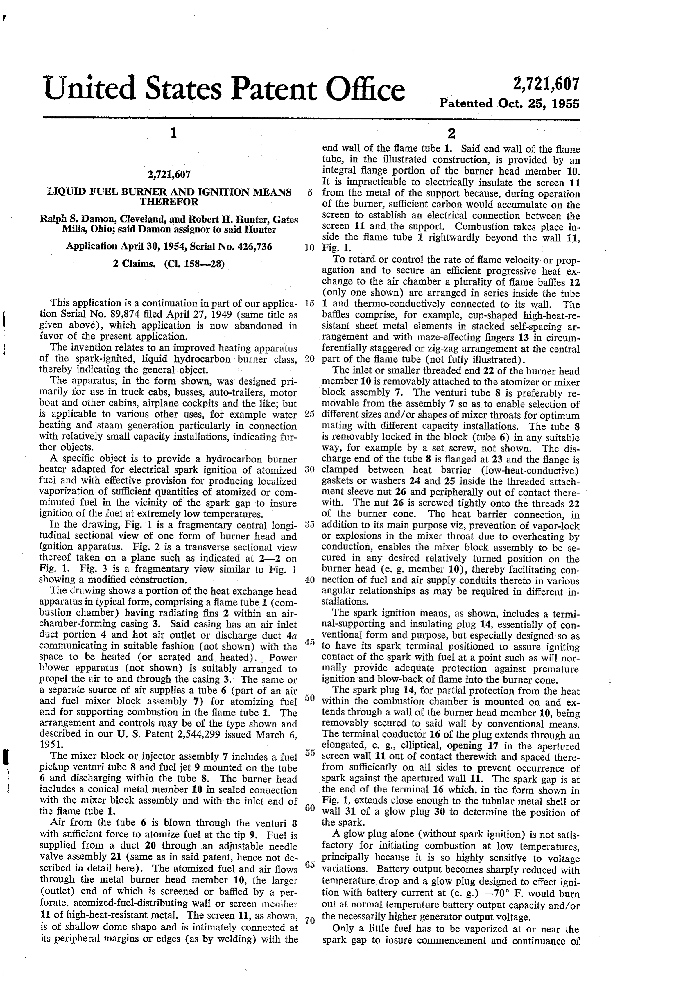
end Wall of the flame tube 1. Said end wall of the flame tube, in the illustrated construction, is provided by an 2,721,607 integral flange portion of the burner head member 10. It is impracticable to electrically insulate the screen 11
LIQUID FUEL BURNER AND IGNITION MEAN 5 from the metal of the support because, during operation THEREFOR of the burner, sufficient carbon would accumulate on the Ralph S. Damon, Cleveland, and Robert H. Hunter, Gates Screen to establish an electrical connection between the Mills, Ohio; said Damon assignor to said Hunter Screen 11 and the support. Combustion takes place in side the flame tube 1 rightwardly beyond the wall 11,
Application April 30, 1954, Serial No. 426,736 0 Fig. 1.
2 Claims. (CI. 158-28) To retard or control the rate of flame velocity or prop agation and to secure an efficient progressive heat ex change to the air chamber a plurality of flame baffles 12 (only one shown) are arranged in series inside the tube
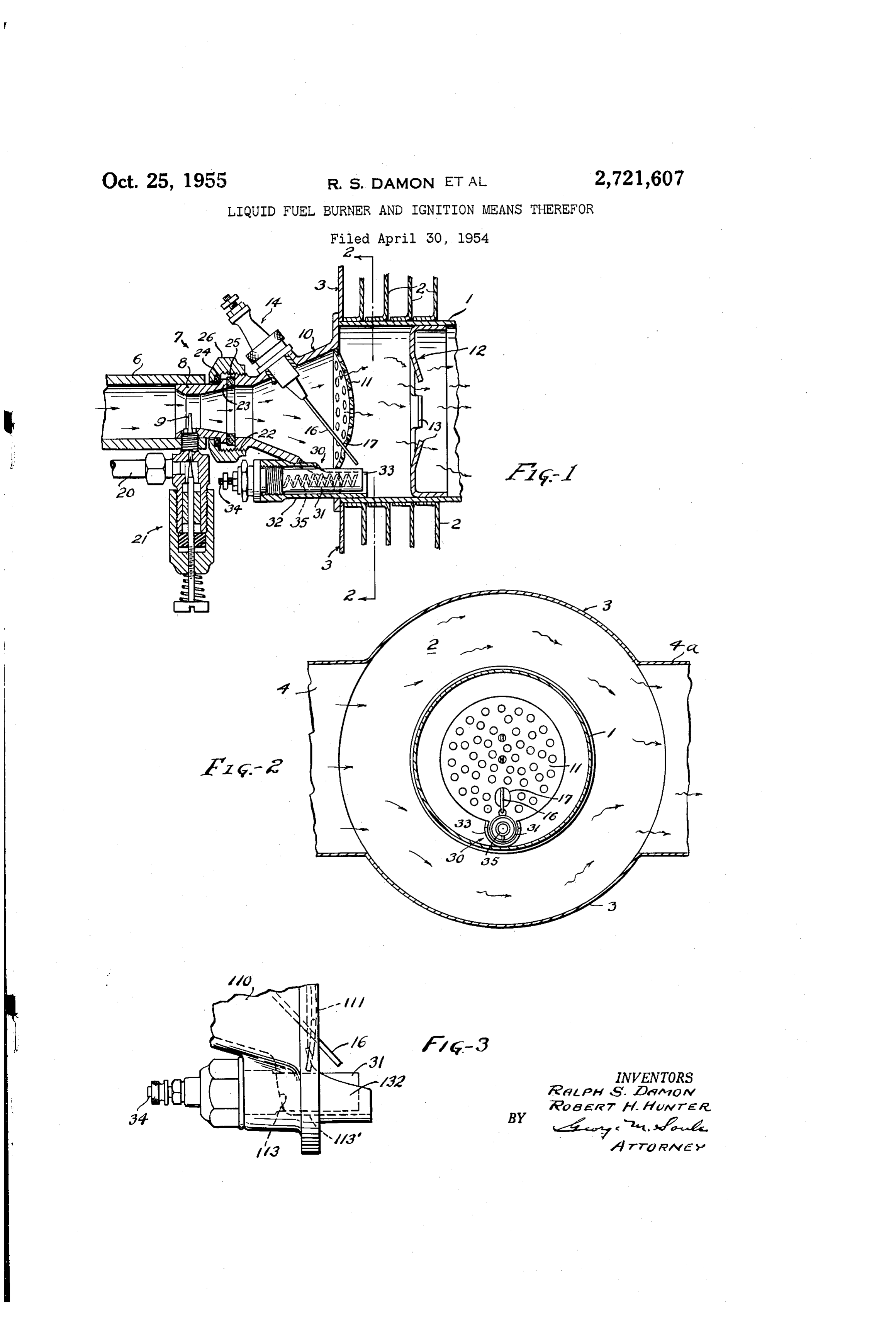
This application is a continuation in part of our applica 1 and thermo-conductively connected to its wall. The tion Serial No. 89,874 filed April 27, 1949 (same title as baffles comprise, for example, cup-shaped high-heat-re given above), which application is now abandoned in sistant sheet metal elements in stacked self-spacing ar favor of the present application. rangement and with maze-effecting fingers 13 in circum The invention relates to an improved heating apparatus ferentially staggered or zig-zag arrangement at the central of the spark-ignited, liquid hydrocarbon burner class, part of the flame tube (not fully illustrated). thereby indicating the general object. The inlet or smaller threaded end 22 of the burner head The apparatus, in the form shown, was designed pri member 10 is removably attached to the atomizer or mixer marily for use in truck cabs, busses, auto-trailers, motor block assembly 7. The venturi tube 8 is preferably re boat and other cabins, airplane cockpits and the like; but movable from the assembly 7 so as to enable selection of is applicable to various other uses, for example water different sizes and/or shapes of mixer throats for optimum heating and steam generation particularly in connection mating with different capacity installations. The tube 8 with relatively small capacity installations, indicating fur is removably locked in the block (tube 6) in any suitable ther objects. way, for example by a set screw, not shown. The dis A specific object is to provide a hydrocarbon burner charge end of the tube 8 is flanged at 23 and the flange is heater adapted for electrical spark ignition of atomized 30 clamped between heat barrier (low-heat-conductive) fuel and with effective provision for producing localized gaskets or washers 24 and 25 inside the threaded attach vaporization of Sufficient quantities of atomized or com ment sleeve nut 26 and peripherally out of contact there minuted fuel in the vicinity of the spark gap to insure With. The nut 26 is screwed tightly onto the threads 22 ignition of the fuel at extremely low temperatures. of the burner cone. The heat barrier connection, in In the drawing, Fig. 1 is a fragmentary central longi addition to its main purpose viz, prevention of vapor-lock tudinal sectional view of one form of burner head and or explosions in the mixer throat due to overheating by ignition apparatus. Fig. 2 is a transverse sectional view conduction, enables the mixer block assembly to be se thereof taken on a plane such as indicated at 2-2 on cured in any desired relatively turned position on the Fig. 1. Fig. 3 is a fragmentary view similar to Fig. 1 burner head (e. g. member 10), thereby facilitating con showing a modified construction. 40 nection of fuel and air supply conduits thereto in various The drawing shows a portion of the heat exchange head angular relationships as may be required in different in apparatus in typical form, comprising a flame tube (com stallations.
bustion chamber) having radiating fins 2 within an air The Spark ignition means, as shown, includes a termi chamber-forming casing 3. Said casing has an air inlet nal-Supporting and insulating plug 14, essentially of con duct portion 4 and hot air outlet or discharge duct 4a ventional form and purpose, but especially designed so as communicating in suitable fashion (not shown) with the 45 to have its spark terminal positioned to assure igniting space to be heated (or aerated and heated). Power contact of the spark with fuel at a point such as will nor blower apparatus (not shown) is suitably arranged to mally provide adequate protection against premature propel the air to and through the casing 3. The same or ignition and blow-back of flame into the burner cone. a separate source of air supplies a tube 6 (part of an air The Spark plug 14, for partial protection from the heat and fuel mixer block assembly 7) for atomizing fuel 50 Within the combustion chamber is mounted on and ex and for supporting combustion in the flame tube . The tends through a wall of the burner head member 10, being arrangement and controls may be of the type shown and removably secured to said wall by conventional means. described in our U. S. Patent 2,544,299 issued March 6, The terminal conductor 16 of the plug extends through an 1951. elongated, e. g., elliptical, opening 17 in the apertured The mixer block or injector assembly 7 includes a fuel 55 Screen wall 11 out of contact therewith and spaced there pickup venturi tube 8 and fuel jet 9 mounted on the tube from sufficiently on all sides to prevent occurrence of 6 and discharging within the tube 8. The burner head Spark against the apertured wall 11. The spark gap is at includes a conical metal member 10 in sealed connection the end of the terminal 16 which, in the form shown in with the mixer block assembly and with the inlet end of 60 Fig. 1, extends close enough to the tubular metal shell or the flame tube 1. wall 31 of a glow plug 30 to determine the position of Air from the tube 6 is blown through the venturi 8 the spark.
with sufficient force to atomize fuel at the tip 9. Fuel is A glow plug alone (without spark ignition) is not satis Supplied from a duct 20 through an adjustable needle factory for initiating combustion at low temperatures, valve assembly 21 (same as in said patent, hence not de principally because it is so highly sensitive to voltage scribed in detail here). The atomized fuel and air flows variations. Battery output becomes sharply reduced with through the metal burner head member 10, the larger temperature drop and a glow plug designed to effect igni (outlet) end of which is screened or baffled by a per tion with battery current at (e.g.) -70 F. would burn forate, atomized-fuel-distributing wall or screen member out at normal temperature battery output capacity and/or i1 of high-heat-resistant metal. The screen 11, as shown, the necessarily higher generator output voltage. is of shallow dome shape and is intimately connected at Only a little fuel has to be vaporized at or near the its peripheral margins or edges (as by welding) with the Spark gap to insure commencement and continuance of
Page 3
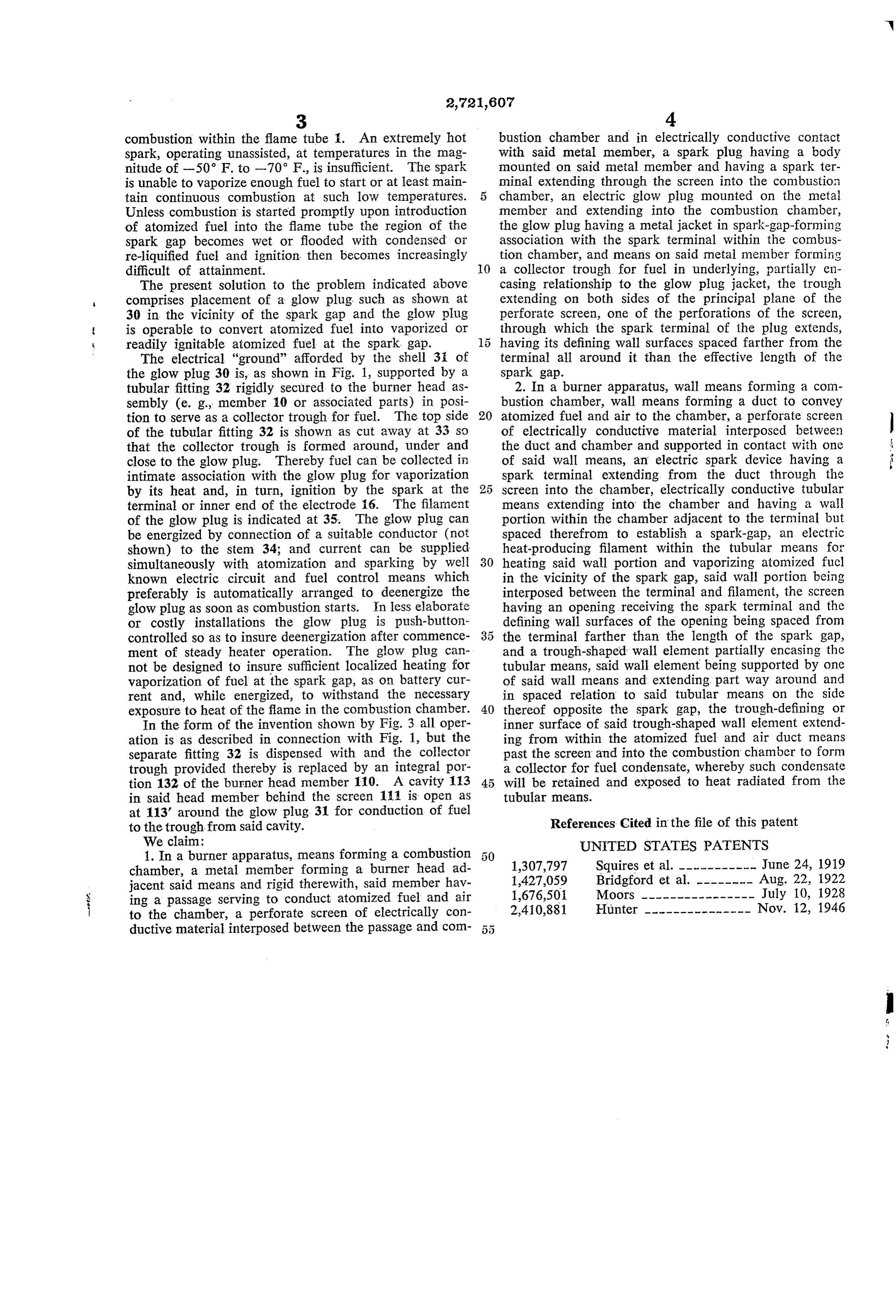
combustion within the flame tube . An extremely hot bustion chamber and in electrically conductive contact spark, operating unassisted, at temperatures in the mag with said metal member, a spark plug having a body nitude of -50 F. to -70 F., is insufficient. The spark mounted on said metal member and having a spark ter is unable to vaporize enough fuel to start or at least main minal extending through the screen into the combustion tain continuous combustion at Such low temperatures. chamber, an electric glow plug mounted on the metal Unless combustion is started promptly upon introduction member and extending into the combustion chamber, of atomized fuel into the flame tube the region of the the glow plug having a metal jacket in spark-gap-forming spark gap becomes wet or flooded with condensed or association with the spark terminal within the combus re-liquified fuel and ignition then becomes increasingly tion chamber, and means on said metal member forming difficult of attainment. 10 a collector trough for fuel in underlying, partially en The present solution to the problem indicated above casing relationship to the glow plug jacket, the trough comprises placement of a glow plug. Such as shown at extending on both sides of the principal plane of the 30 in the vicinity of the spark gap and the glow plug perforate screen, one of the perforations of the screen, is operable to convert atomized fuel into vaporized or through which the spark terminal of the plug extends, readily ignitable atomized fuel at the spark gap. having its defining wall surfaces spaced farther from the The electrical "ground' afforded by the shell 3i of terminal all around it than the effective length of the the glow plug 30 is, as shown in Fig. 1, supported by a Spark gap.
tubular fitting 32 rigidly secured to the burner head as 2. In a burner apparatus, wall means forming a com sembly (e. g., member 10 or associated parts) in posi bustion chamber, wall means forming a duct to convey tion to serve as a collector trough for fuel. The top side 20 atomized fuel and air to the chamber, a perforate screen of the tubular fitting 32 is shown as cut away at 33 so of electrically conductive material interposed between that the collector trough is formed around, under and the duct and chamber and supported in contact with one close to the glow plug. Thereby fuel can be collected in of said wall means, an electric spark device having a intimate association with the glow plug for vaporization spark terminal extending from the duct through the by its heat and, in turn, ignition by the spark at the 25 screen into the chamber, electrically conductive tubular terminal or inner end of the electrode 16. The filament means extending into the chamber and having a wall of the glow plug is indicated at 35. The glow plug can portion within the chamber adjacent to the terminal but be energized by connection of a suitable conductor (not spaced therefrom to establish a spark-gap, an electric shown) to the stem 34; and current can be supplied heat-producing filament within the tubular means for simultaneously with atomization and sparking by Well 30 heating said wall portion and vaporizing atomized fuel known electric circuit and fuel control means which in the vicinity of the spark gap, said wall portion being preferably is automatically arranged to deenergize the interposed between the terminal and filament, the Screen glow plug as soon as combustion starts. In less elaborate having an opening receiving the spark terminal and the or costly installations the glow plug is push-button defining wall surfaces of the opening being spaced from controlled so as to insure deenergization after commence 35 the terminal farther than the length of the spark gap, ment of steady heater operation. The glow plug can and a trough-shaped wall element partially encasing the not be designed to insure sufficient localized heating for tubular means, said wall element being supported by one vaporization of fuel at the spark gap, as on battery cur of said wall means and extending part way around and rent and, while energized, to withstand the necessary in spaced relation to said tubular means on the side exposure to heat of the flame in the combustion chamber. 40 thereof opposite the spark gap, the trough-defining or In the form of the invention shown by Fig. 3 all oper inner surface of said trough-shaped wall element extend ation is as described in connection with Fig. 1, but the ing from within the atomized fuel and air duct means separate fitting 32 is dispensed with and the collector past the screen and into the combustion chamber to form trough provided thereby is replaced by an integral por a collector for fuel condensate, whereby such condensate tion 132 of the burner head member 110. A cavity 113 will be retained and exposed to heat radiated from the in said head member behind the screen 11 is open as tubular means.
at 113' around the glow plug. 31 for conduction of fuel to the trough from said cavity. References Cited in the file of this patent We claim: UNITED STATES PATENTS 1. In a burner apparatus, means forming a combustion chamber, a metal member forming a burner head ad 1,307,797 Squires et al. ----------- June 24, 1919 jacent said means and rigid therewith, said member hav 1,427,059 Bridgford et al. -------- Aug. 22, 1922 ing a passage serving to conduct atomized fuel and air 1,676,501 Moors ---------------- July 10, 1928 i to the chamber, a perforate screen of electrically con 2,410,881 Hunter --------------- Nov. 12, 1946 ductive material interposed between the passage and com 5 5
Provenance
- Collection
- Cited prior art
- Original PDF
- patentimages.storage.googleapis.com →
- Filed
- 1954-04-30
- Pages
- 3
- Method
- pdftotext (the PDF's own text layer) + pdftoppm 300dpi page scans
- Source
- Google Patents bibliographic record
- Granted
- 1955-10-25
- Inventors
- Ralph S Damon; Robert H Hunter; HUNTER
- Transcribed from
- patentimages.storage.googleapis.com →