patent · US4134719
Multi-flame fuel burner for liquid and gaseous fuels
16 January 1979
Page 1 — bibliographic record
United States Patent (19) 11 4,134,719 Velie 45) Jan. 16, 1979 (54) MULT-FLAME FUEL BURNER FOR 2,630,461 3/1953 Sachsse et al. ......................... 431/89 LIQUID AND GASEOUS FUELS 2,964,103 12/1960 Ryder ....................... ... 431/264 3,754,853 8/1973 Braucksiek et al. . ... 431/347 76 Inventor: Wallace W. Wellie, 520 W. Emerson 3,843,309 10/1974 Lambiris .............. ... 43/284 St., Upland, Calif. 91786 3,847,537 11/1974 Velie ................ ... 43/347 3,909, 188 9/1975 Velie.... ... 43/347 (21) Appl. No.: 726,795 4,025,282 5/1977 Reed .................................... 43/328 (22 Filed: Sep. 27, 1976 FOREIGN PATENT DOCUMENTS 51) Int. Cl.?........ O 0 o w w a do 8 & F23M 9/06 1395430 3/1965 France ..................................... 431/286 52 U.S. C. .................................... 431/171; 431/286; Primary Examiner-Carroll B. Dority, Jr. 431/347; 239/422; 239/416.1; 239/424; Attorney, Agent, or Firm-Fleit & Jacobson
58) Field of Search ............... 431/347, 284, 171, 180, 57 ABSTRACT 431/286; 239/422,426, 400, 416.1, 424,524 A multi-flame fuel burner comprises a plurality of air 56) References Cited atomizing fuel nozzles and sources of pressurized gas
1,241,135 9/1917 Mastenbrook ....................... 239/400 zle. A flame spreader is employed in combination with 1,400,657 12/1921 Brodie............. ... 239/422 each air-atomizing nozzle to stabilize and shape the 1,435,991 11/1922 Stevenson et al. ................... 239/400 flame. The number of nozzles and associated flame 2,287,246 6/1942 Hess ................. ... 431/180 spreaders are set to provide the desired burn rate. 2,393,887 1/1946 Clements. ... 239/416.1 2,466,100 4/1949 Harrah .............................. 239/416.1 9 Claims, 5 Drawing Figures
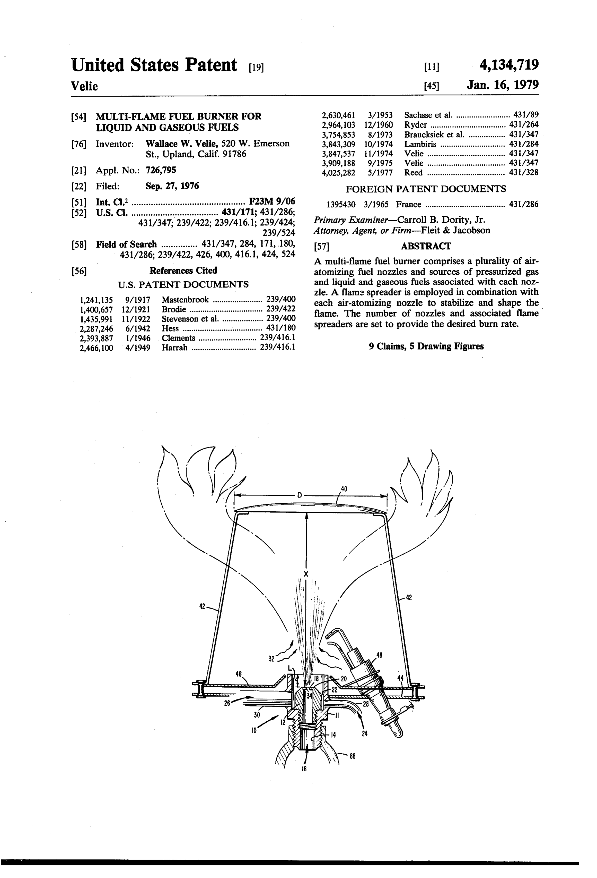
/ . 40 /
Page 2
Drawing sheet — no readable text.
Page 3
Drawing sheet — no readable text.
Page 4
fication and claims, taken in conjunction with the ac
MULTI-FLAMEFUEL BURNERFORLIQUID AND companying drawings.
GASEOUS FUELS SUMMARY OF THE INVENTION
CROSS-REFERENCE TO RELATED PATENT 5 A simple multi-flame fuel burner is provided having a This application is related to my U.S. Pat. No. plurality of air-atomizing nozzles, a source of pressur 3,909,188. ., ; ized gas for dispersion of the fuel, sources of liuid and gaseous fuels, and regulators as required for regulating
BACKGROUND OFTHE INVENTION the flow of pressurized gas and fuel to the air-atomizing A fuel nozzle is essential to most fuel burners and 10 nozzles. A valve is provided in the delivery line to the consists of a device to prepare the fuel, gaseous or liq nozzles from the source of each of the liquid and gase uid, for efficient combustion. These devices have a ous fuels to select the type of fuel (i.e., liquid or gaseous) variety of configurations, depending upon the physical to be delivered to the nozzles. Suitable means may be characteristics of the fuel being consumed. optionally provided in the lines from the gas and liquid Almost exclusively, gaseous fuel nozzles consist of 15 and gaseous fuel supplies to regulate the air and fuel simple metering devices or orifices. Gas under its natu pressures to the air-atomizing nozzles. Also, a flame ral or supply system pressure is forced through the spreader may be employed downstream of the nozzles orifice, downstream of which is usually a tube to con to stabilize and shape the flames.
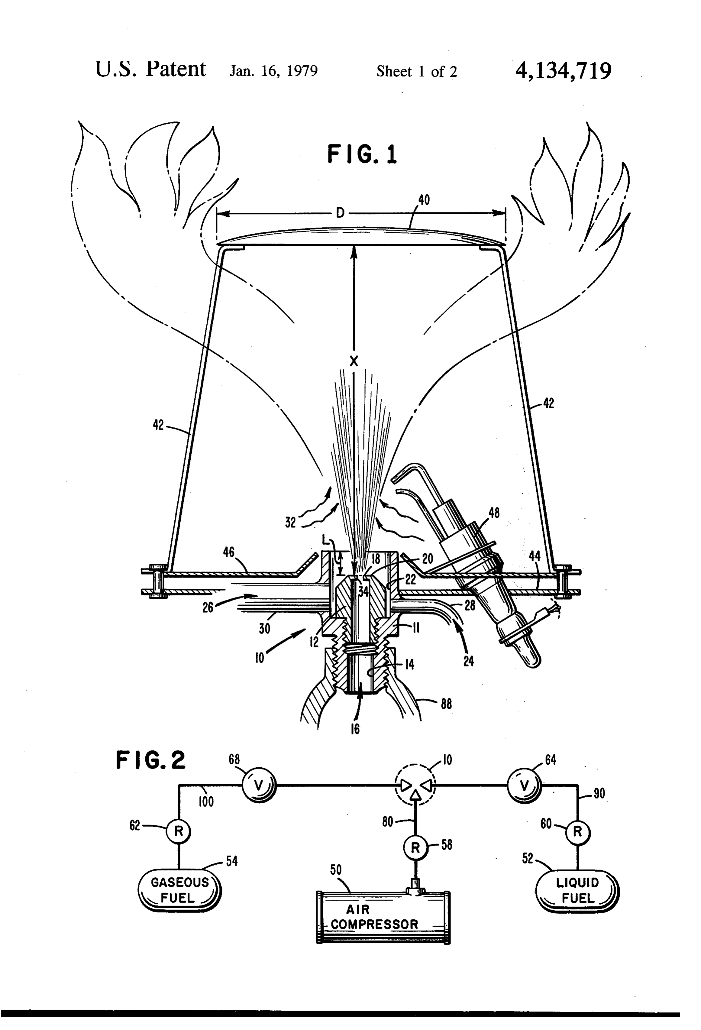
duct the naturally aspirated mixture of fuel and en BRIEF DESCRIPTION OF THE DRAWINGS trapped air to a burner head. By contrast, liquid fuel 20 FIG. 1 shows one of the plurality of air-atomizing nozzles typically use high fuel pressure and swirl and nozzles of this invention;
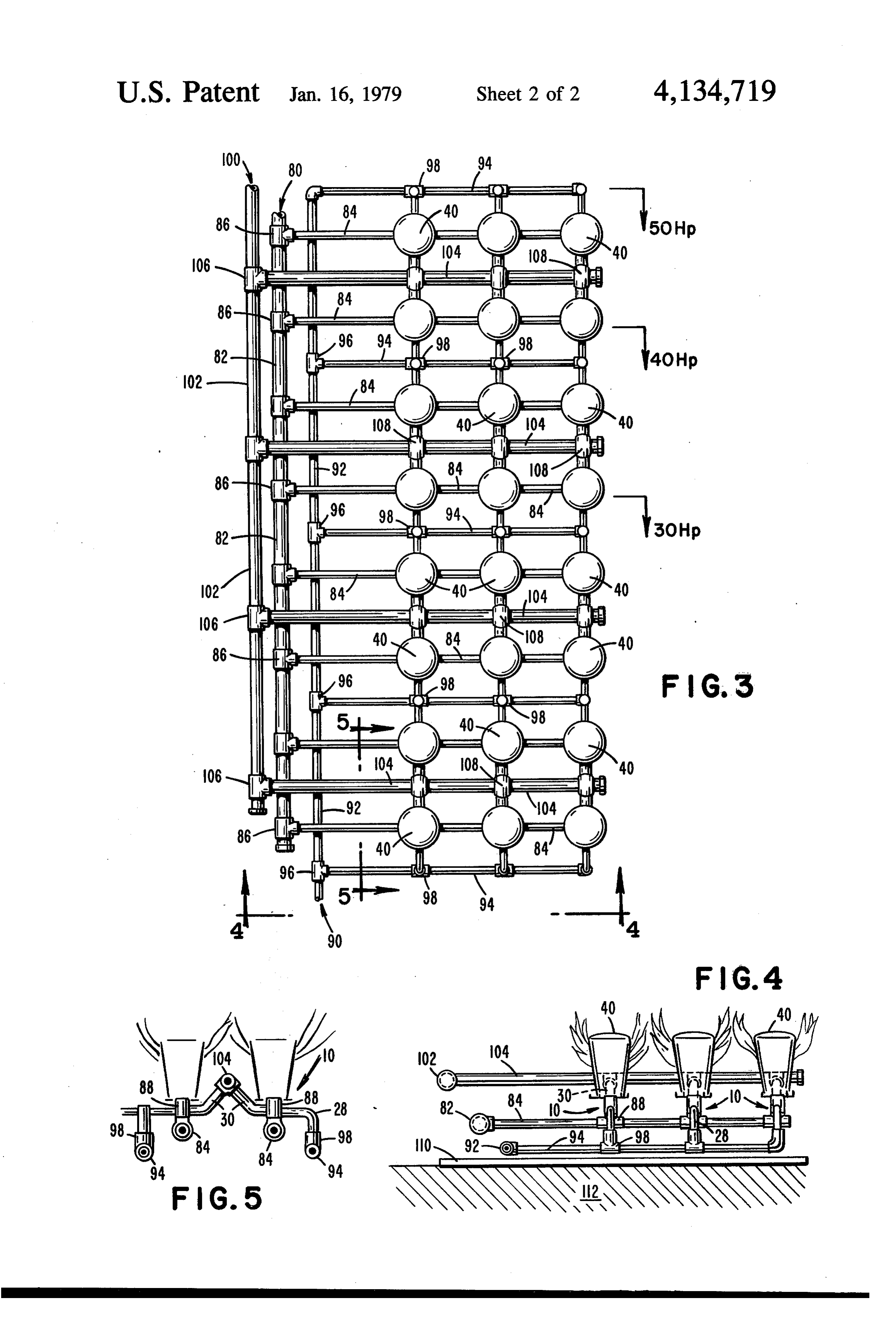
mechanical techniques to create a spray which is di FIG. 2 shows an embodiment of this invention illus rected into the burner where it is mixed with a forced trating supply of air and burned. A disadvantage of prior art 25 ing onethe of relationship of the major components includ the plurality of air-atomizing nozzles;
gaseous and liquid fuel nozzles is that they have func FIG. 3 is a plan view of the multi-flame fuel burner of tionally different designs for fundamentally different this invention including a plurality of air-atomizing processes and therefore are not mutually interchange nozzles and having a dual fuel burning capability; able. FIG. 4 is a vertical end view of the multi-flame fuel There is an increasing need for burners having multi ple fuel capability, particularly those which can burn 30 burner and of FIG. 3 taken in the direction of arrows 4-4;
gaseous as well as liquid fuels. Moreover, there is a FIG. 5 is a partial vertical side view of the multi growing need for dual fuel burners for larger commer flame cial or indistrial sized heating appliances, particularly in arrowsfuel 5-5.
burner of FIG. 3 taken in the direction of view of the increasing uncertainties about the availabil 35 ity of fuels. For example, a burner which can consume DESCRIPTION OF THE PREFERRED liquid fuels in a manner approximating gaseous fuels EMBODEMENTS (i.e., natural convection combustion) is of particular Referring to FIG. 1, the fuel atomizer comprises an interest since it can replace gas burners in applications air-atomizing nozzle 10 having an open ended atomizer which rely solely upon gaseous energy sources. In par housing 11 containing a compressible flow nozzle 12 at ticular, gas burners for industrial processes such as boil the terminus of an air or gas conduit 14 and so con ers, hearths, heat treatment, and baking are candidates structed that when a compressed gas 16 is expanded for dual fuel burners. through the aperture 18 a region is created in the vicin Accordingly, it is an object of this invention to utilize ity of surfaces 20 and 22 such that liquid or gaseous fuel the characteristics of a pneumatic type atomizer to pro 45 24 and 26 introduced through conduits 28 and 30, re vide a simple burner which is capable of burning gase spectively, adjacent to surfaces 20 and 22 is efficiently ous as well as liquid fuels and which has multiple noz and completely dispersed along with ambient air 32. zles or flame heads to increase the output of the burner The specific dimensions of the air-atomizing nozzle assembly. 10 are important to effective performance of the nozzle It is a further object of this invention to provide a 50 using both liquid and gaseous fuels. These dimensions burner which, in its simplest form, comprises a plurality are set forth in detail in my U.S. Pat. No. 3,909,188, the of air-atomizing nozzles and sources of pressurized gas disclosure of which is expressly incorporated herein by and liquid and gaseous fuels associated with each noz reference. Briefly, the thickness of the edge 34 of air zle. aperture 18 is desirably less than the hydraulic diameter It is a still further object of this invention to provide 55 (i.e., aperture area -- aperture perimeter) of air aperture a multi-flame fuel burner which will distribute heat 18. Furthermore, the ratio of the mean diameter of gas evenly over the heat transfer surface. conduit 14 to the hydraulic diameter of air aperture 18 Yet another object of this invention is to provide a should be greater than approximately 10.
multi-flame fuel burner which is naturally aspirating. The best hydraulic diameter for air aperture 18 is Still another object of this invention is to provide a between about 10 and 30 thousandths of an inch and the multi-flame fuel burner which is cpable of cross-ignition preferred thickness of edge 34 is about 5 thousandths of among flame heads from a single ignited flame head. an inch. The exit area of atomizing housing 11 should be Another object of this invention is to provide a multi less than about 0.4 square inch for a liquid fuel disper flame fuel burner which produces exceptionally clean sion rate of about 1 gp.h. At the same time, the exit area and high temperature combustion products for applica 65 should not be so small that operation on gaseous fuel tion heating efficiency. . .. produces excessive exit velocity. Still further objects and advantages of this invention The length (L) of the open end of the atomizer hous will become apparent upon reading the following speci ing 11 above air aperture 18 should be minimized to
Page 5
enhance aspiration of the ambient air at the housing exit. plurality of air-atomizing nozzles 10 and associated Approximately one-fourth inch or less has been found flame spreaders 40 such as shown in FIG. 3. Each air to be acceptable for this length (L). Concurrently, the atomizing nozzle 10 is attached to a gas or air manifold fuel inlets should be as far below the aperture end of system 80 which supplies compressed air, for example, nozzle 12 as practical to avoid surface disturbance of 5 for the atomizer. Air manifold system 80 includes main liquid fuel and to uniformly distribute gaseous fuels air conduit or line 82 and a plurality of secondary air around nozzle 12 prior to dispersion. On the other hand, conduits or lines 84 attached to the main air line by an open ended atomizer body is not a mandatory re fittings 86. In the embodiment illustrated, three air-ato quirement of a pneumatic type atomizer and adequate mizing nozzles 10 are attached to each secondary air performance is possible by placing fuel conduits 28 and 10 line by means of fittings 88 although it will be appreci 30 close to surface 20 and adjacent to the aperture 18. ated that any number of nozzles may be employed. Still referring to FIG. 1, flame spreader 40 can be The liquid fuel is supplied to the nozzles 10 through formed from any conventional material such as stainless liquid fuel manifold system 90 which includes main and steel or ceramics. Flame spreader 40 is generally disc secondary liquid fuel conduits or lines 92 and 94, respec shaped and typically has a flat, planar or convex flame 15 tively, connected together by fittings 96. The secondary engaging surface. Flame spreader 40 may be supported liquid fuel lines 94 are in turn attached to conduits 28 of relative to the air-atomizing nozzle by legs 42 attached air-atomizing nozzles 10 via fittings 98. to burner base 44. Above the burner base 44 and at In like manner, the gaseous fuel is supplied through tached to it as an optional flame shield 46. Ignitor 48 is gaseous fuel manifold system 100 comprising main and attached to burner base 44 and is of conventional de 20 secondary gaseous fuel conduits or lines 102 and 104, sign, such as a high voltage spark ignitor. Although respectively, connected together by fittings iO6. Sec more than one ignitor may be employed, only one is ondary gaseous fuel lines 104 are in turn connected to required in the over-all multi-flame fuel burner shown conduits 30 of air-atomizing nozzles 10 via fittings 108. in FIGS. 3-5 because the system is capable of cross The operation of the multi-flame fuel burner system is ignition among nozzles or flame heads from a single 25 essentially the same as described above with reference ignited flame head. to FIGS. 1 and 2. The air-atomizing nozzles 10 may be During operation, primary air from gas conduit 14 arranged in any desired configuration and spacing de disperses the fuel from liquid or gaseous fuel conduits 28 pending on the installation (e.g., boiler) in which they and 30, respectively, into fine particles or a mist as it are to be used. A typical spacing is a uniform spacing of expands through air aperture 18 of nozzle 12. These fine 30 about 7/8 inches between the centers of the nozzles. particles or mist are mixed with secondary air 32 which The number of nozzles may be varied to meet the burn is drawn into the system above the atomizer by natural rate requirements of the particular application, for ex aspiration. The sprayed fuel is ignited by ignitor 48 or ample, for a 30Hp, 40 Hip or 50Hp boiler as indicated by cross-ignition from an adjacent nozzle and the result in FIG. 3. The burner may be mounted in any manner ing flame directed perpendicular to flame spreader 40. 35 required but is shown for ease of illustration suspended At flame spreader 40, the flame is stabilized and shaped, above tray 110 lying on floor or base 112. the upper surface of flame shield 46 acting as a radiation The multiple flame head burner is capable of burn shield. rate modulation by concurrently adjusting air and fuel Flame spreader 40 should be positioned perpendicu pressure over the burn rate range of interest. Burn rate lar to the air-atomizing nozzle and approximately cen modulation may be continuous or abrupt (high or low tered (i.e., within about 0.25 inch) on the nozzle. For rate) depending upon the requirements of the applica optimum combustion, flame spreader 40 should be in tion. A conventional control system (not shown) is used the gaseous or hydroxyl type combustion zone. This to accommodate the modulation.
zone is downstream from the drop vaporization Zone By way of illustration, burning rates in the range of and upstream from the yellow flame or carbonaceous 45 0.1 to 1.0 g.p.h. per nozzle or flame head may conve combustion zone. For optimum burning characteristics niently be provided using the burner system at primary for most burner applications, it has been found best to air pressures between about 8 and 18 p.s.i.g. use a ratio of flame spreader diameter (D) to axial sepa Liquid fuels such as fuel oil which have no measur ration distance (X) of about 1. Further details with able vapor pressure at ambient conditions require a respect to the flame spreader and ignitor are found in 50 means of delivery (not shown). By contrast, most gase my U.S. Pat. No. 3,909,188. ous fuels (e.g., hydrogen, methane, petroleum gases) FIG. 2 is a schematic representation of an embodi have a substantial vapor pressure which may be used for ment of the present invention but showing only one of fuel delivery or the gaseous fuels may be obtained under the plurality of air-atomizing nozzles for ease of illustra pressure from a central delivery system. Although air tion. Broadly speaking, the fuel burner includes a source 55 has been illustrated herein as the dispersion gas, the of pressurized gas, specifically illustrated as air com dispersion gas may itselfbe a gaseous fuel having signifi pressor 50, for dispersion of the fuel, sources of liquid cant vapor pressure at ambient conditions such as pro and gaseous fuels, 52 and 54, respectively, an air-atomiz pane, butane, methane, etc.
ing nozzle 10, and regulators 58, 60 and 62 for regulat Finally, the term air-atomizing nozzle is used ing, if necessary, the flow of pressurized gas and liquid throughout the specification and claims in its generic and gaseous fuels, respectively, to the air-atomizing sense as meaning a nozzle, such as the type shown in nozzle. A valve 64 is provided in the delivery line from FIG. 1, in which fuel is prepared for combustion by the source of liquid fuel 52 to the nozzle 10 and a similar low-pressure dispersion using a compressible gas (e.g., valve 68 in the delivery line from the source of gaseous air) as the dispersing medium. In low-pressure atomiza fuel 54 to the nozzle 10 to select the type of fuel (i.e., 65 tion, primary air (gas) is delivered to the nozzles at liquid or gaseous) delivered to the nozzle. relatively low pressure (e.g., 1 to 25 p.s.i.g.) and used to A preferred embodiment of the over-all multi-flame atomize fuel also delivered to the nozzles at low pres fuel burner is shown in FIGS. 3-5 and comprises a sure (e.g., 1 to 4 p.s.i.g.).
Page 6
The invention in its broader aspects is not limited to tion flame for stabilizing and shaping said combustion the specific details shown and described, and departures flame.
may be made from such details without departing from 2. The multi-flame air-atomizing fuel burner system the principles of the invention and without sacrificing of claim 1 in which said primary gas is air and said its chief advantages. For example, more sophisticated primary gas delivery means includes air compressor SeaS, means may be employed for supplying the liquid fuel to the air-atomizing nozzles such as shown in my U.S. Pat. of3.claim The multi-flame air-atomizing fuel burner system 1 in which the ratio of flame spreader diameter
No. 3,909,188. Accordingly, the invention should not be to separation distance between said flame spreader and limited to the single embodiment illustrated above but O each of said air-atomizing nozzle means is about 1. only as defined in the appended claims. 4. The multi-flame air-atomizing fuel burner system I claim: of claim 1 in which said means for delivering gaseous 1. A multi-flame air-atomizing fuel burner system fuel to said air-atomizing nozzle means includes means comprising a plurality of air-atomizing nozzle means for for regulating the flow of gaseous fuel to said air-ato using primary gas under pressure to disperse fuel, each 15 mizing nozzle means.
of said air-atomizing nozzle means including a substan 5. The multi-flame air-atomizing fuel burner system tially vertically oriented, open ended atomizer housing, of claim 4 in which said means for regulating the flow of each of said housings having an aperture through which gaseous gaseous fuel to said air-atomizing nozzle means is a fuel pressure regulator.
said primary gas is expanded to disperse said fuel, means 20 6. The multi-flame air-atomizing fuel burner system for delivering liquid fuel to said atomizer housing of of claim 1 in which said each of said air-atomizing nozzle means adjacent said of fuel delivered to saidmeans for controlling the type air-atomizing nozzle means aperture, means for delivering gaseous fuel to said at comprises valve means.
omizer housing of each of said air-atomizing nozzle 7. The air-atomizing fuel burner system of claim 1 in means adjacent said aperture, means for selecting the 25 which said air-atomizing nozzle means comprises an air type of fuel delivered to said air-atomizing nozzle aperture having a hydraulic diameter and having an means, means for delivering primary gas under pressure edge with a thickness approximately equal to or less through said aperture of each of said air-atomizing noz than the hydraulic diameter of said air aperture. zle means to disperse one of said fuels so that the dis 30 8. The multi-flame air-atomizing fuel burner system persed fuel may be ignited in the presence of secondary to of claim 7 in which said hydraulic diameter is about 10 30 mills, air to produce a combustion flame, said air-atomizing 9. The multi-flame air-atomizing fuel burner system nozzle means being spaced apart and arranged in a pat of claim tern to provide cross-ignition from a single ignited noz dispersed1 fuel and further comprising means for igniting the in the presence of said secondary air to zle means, and flame spreader means located down 35 produce said combustion flame in combination with at stream of each of said air-atomizing nozzle means in the least one of said air-atomizing nozzle means. gaseous or hydroxyl type combustion zone of a combus is
Provenance
- Collection
- Cited prior art
- Original PDF
- patentimages.storage.googleapis.com →
- Filed
- 1976-09-27
- Pages
- 6
- Method
- pdftotext (the PDF's own text layer) + pdftoppm 300dpi page scans
- Source
- Google Patents bibliographic record
- Granted
- 1979-01-16
- Inventors
- Wallace W. Velie
- Transcribed from
- patentimages.storage.googleapis.com →