patent · US3915623
Wind-proof cigarette lighter burner
28 October 1975
Page 1
United States Patent (19) 11, 3,915,623 Wormser (45) *Oct. 28, 1975 54 WIND-PROOF CIGARETTE LIGHTER 56) References Cited BURNER UNITED STATES PATENTS 75) Inventor: Alex F. Wormser, Marblehead, 1,079,327 1 1/1913 Chadborn ...... ............... 239/399 Mass. 1,404,610 1/1922 Higgins............................... 239/399 (73). Assignee: Wingaersheek, Inc., Peabody, Mass. 1,817,066 8/1931 Crow...... -a a a 2391403 3,510,238 5/1970 Biber.................................. 431/350 *) Notice: The portion of the term of this 3,844,707 10/1974 Wormser ............................ 43 1/347 patent subsequent to Oct. 29, 1991, FOREIGN PATENTS OR APPLICATIONS has been disclaimed.
804,375 8/1936 France................................ 2391.399
(21) Appl. No.: 503,611 Primary Examiner-Carroll B. Dority, Jr. Attorney, Agent, or Firm-Kenway & Jenney
Related U.S. Application Data (63) Continuation-in-part of Ser. No. 389,534, Aug. 20, 57 ABSTRACT 1973, Pat. No. 3,844,707, which is a A miniature burner construction disclosed herein em continuation-in-part of Ser. Nos. 142,402, May 1 1, ploys a jet pump driven by a fuel jet so as to aspirate 1971, abandoned, and Ser. No. 535,215, March 17, air for combustion of the fuel. The jet pump opens 1966, abandoned, and Ser. No. 728,933, May 14, into a flame tube in which is positioned a disk-like 1968, abandoned, and Ser. No. 761,372, July 18, flameholder having a series of peripheral notches
1971, abandoned. around a central hub. The central hub provides reli able re-circulation and ignition of the incoming air 52 U.S. C. ................. 431/347; 431/353; 239/399 fuel mixture. Critical ratios relating the cooperating (51) int. C.’.......................................... F23D 13/12 dimensions of the jet pump and burner are disclosed 58) Field of Search........... 431/344, 347, 353, 354; together with the ranges over which satisfactory oper
6 Claims, 3 Drawing Figures
Q NYNYNYNNNYNYNY
Page 2
Drawing sheet — no readable text.
Page 3
WNED-PROOF CIGARETTE LIGHTER BURNER about 4 inch or less and having proportions such that
RELATIONSHIP TO EARLIER CASES
This application is a continuation-in-part of applica
tion Ser. No. 389,534, filed Aug. 20, 1973, now patent D2ID is about 17 No. 3,844,707, for a Low-Cost, Wind-Proof Cigarette L2fO2 is about 3.3 Lighter Burner, which application is itself a continua L3 D2 is about 15
tion-in-part or otherwise related to applications Ser. Af(D4): is about 0.05
17, 1966; 728,933 filed May 14, 1968; 761,372 filed O BRIEF DESCRIPTION OF THE DRAWINGS
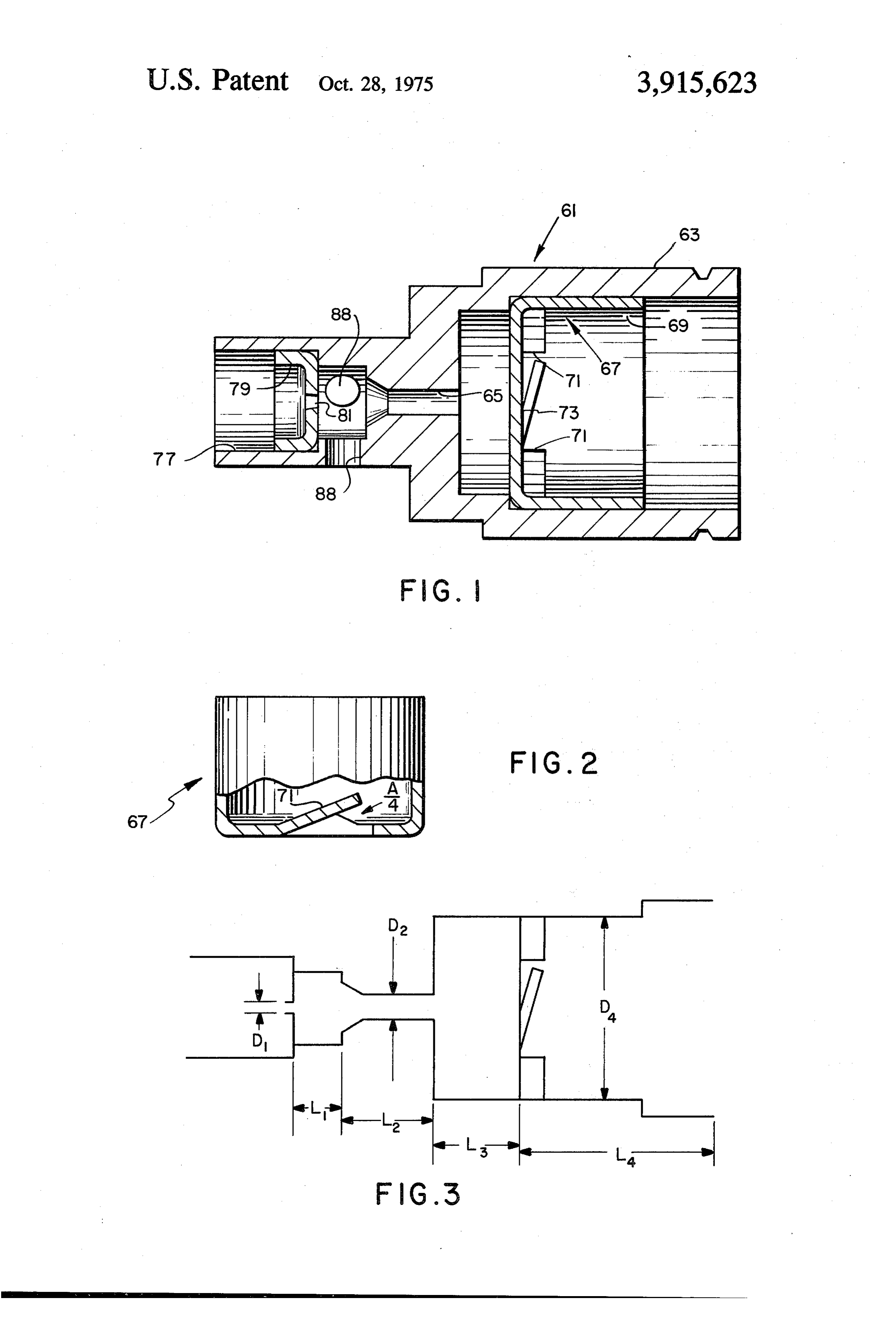
latter applications are all now abandoned. Applicant FIG. 1 is a side view in section of a burner con disclaims any part of the term of any patent which is structed in accordance with the present invention; sues on the present application which extends beyond FIG. 2 is a side view of a flameholder, partially bro the term of any patent issuing from application Ser. No. 15 ken away, employed in the burner of FIG. 1; and 389,534, now patent No. 3,844,707. FIG. 3 is a diagrammatic view of the burner of FIG. BACKGROUND OF THE INVENTION 1 with various critical dimensions and relationships being designated for reference to various critical ratios
This invention relates to burners of exceptionally discussed in the specification. small size, i.e. 4 inch diameter or less, and particularly 20 Corresponding reference characters indicate corre to such burners adapted for use in a cigarette lighter sponding parts throughout the several views of the operating on gaseous fuel. drawings.
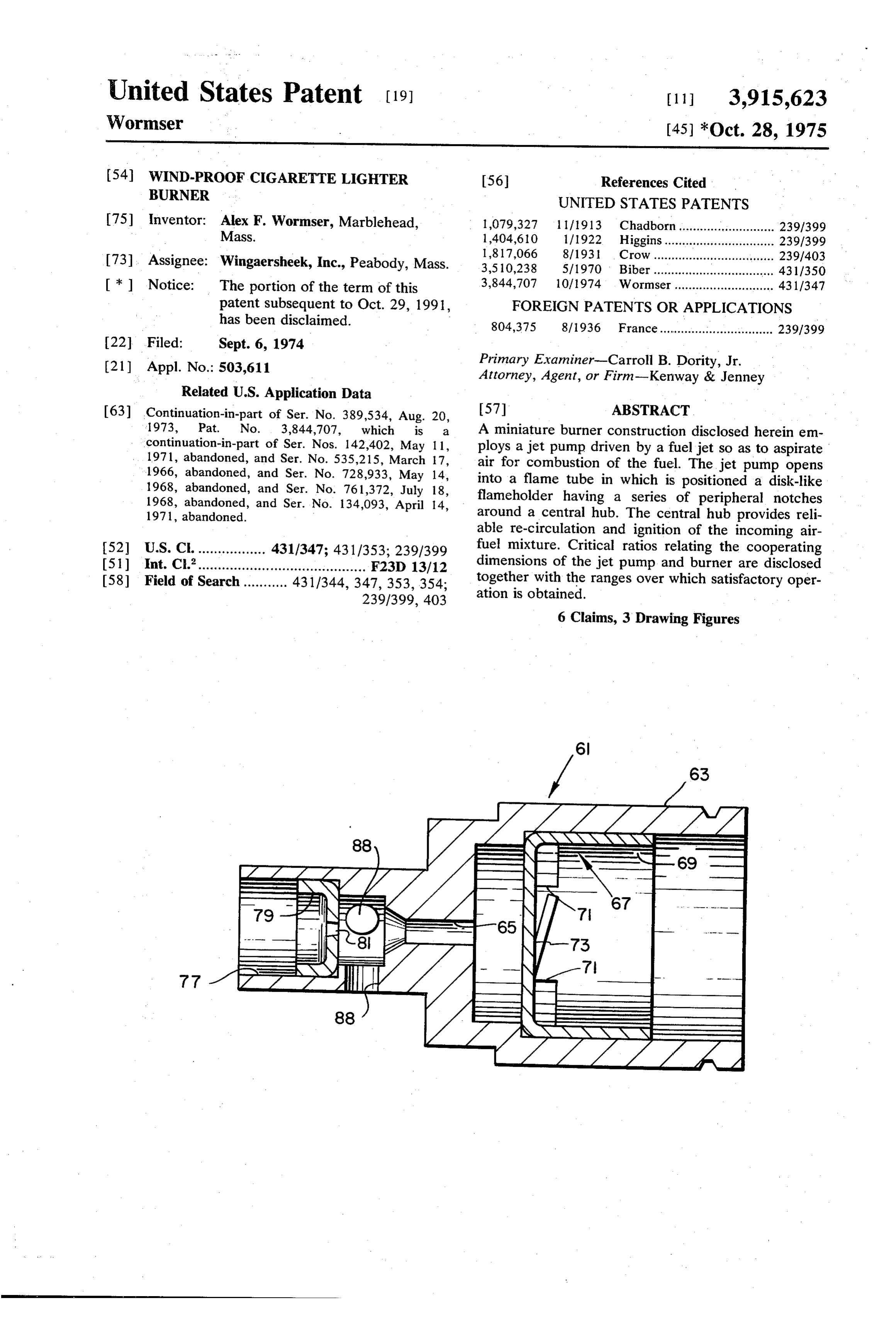
While cigarette lighters operating on gaseous fuel have been available previously, lighters of this type DESCRIPTION OF THE PREFERRED have in the past been particularly susceptible to blow 25 EMBODEMENT out problems in the presence of ambient winds or even FIG. illustrates a burner construction in which vari relatively gentle air movement. ous of the parts are constructed of solid material, i.e. Among the several objects of the present invention die cast or machined metal, rather than the stamped may be noted the provision of a cigarette lighter oper sheet metal construction disclosed in application Ser. ating on gaseous fuel which is relatively blowout-proof. 30 No. 389,534, now U.S. Pat. No. 3,844,707. Referring Other objects and features will be in part apparent and now to FIG. 1, a die cast member 61 provides the flame in part pointed out hereinafter. tube 63 and a venturi 65 having a convergent inlet. A While burners in accordance with the present inven stamped sheet metal flameholder 67 is inserted into the tion to some extent employ the principles disclosed in flame tube, the flameholder being similar to that em my earlier applications relating to larger burners, i.e. 35 ployed in the embodiment of application Ser. No.
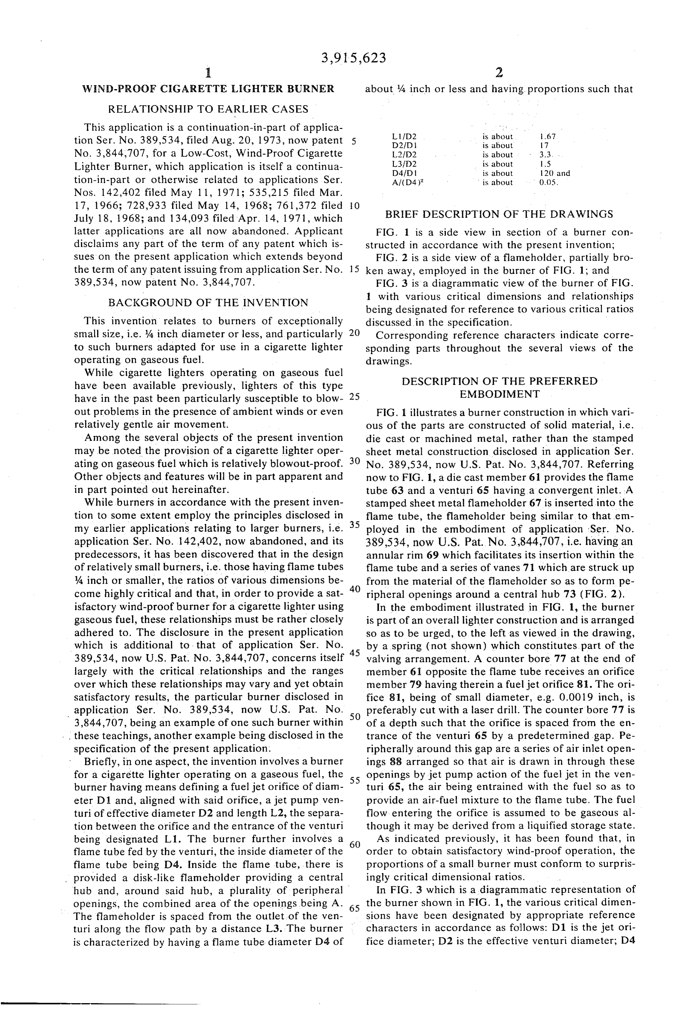
application Ser. No. 142,402, now abandoned, and its 389,534, now U.S. Pat. No. 3,844,707, i.e. having an predecessors, it has been discovered that in the design annular rim 69 which facilitates its insertion within the of relatively small burners, i.e. those having flame tubesflame tube and a series of vanes 71 which are struck up A inch or smaller, the ratios of various dimensions be 40 from the material of the flameholder so as to form pe come highly critical and that, in order to provide a sat ripheral openings around a central hub 73 (FIG. 2). isfactory wind-proof burner for a cigarette lighter using In the embodiment illustrated in FIG. 1, the burner gaseous fuel, these relationships must be rather closely is part of an overall lighter construction and is arranged adhered to. The disclosure in the present application so as to be urged, to the left as viewed in the drawing, which is additional to that of application Ser. No. 45 by a spring (not shown) which constitutes part of the 389,534, now U.S. Pat. No. 3,844,707, concerns itself valving arrangement. A counter bore 77 at the end of largely with the critical relationships and the ranges member 61 opposite the flame tube receives an orifice over which these relationships may vary and yet obtain member 79 having therein a fuel jet orifice 81. The ori satisfactory results, the particular burner disclosed in fice 81, being of small diameter, e.g. 0.0019 inch, is application Ser. No. 389,534, now U.S. Pat. No. SO preferably cut with a laser drill. The counterbore 77 is 3,844,707, being an example of one such burner within of a depth such that the orifice is spaced from the en these teachings, another example being disclosed in the trance of the venturi 65 by a predetermined gap. Pe specification of the present application. ripherally around this gap are a series of air inlet open Briefly, in one aspect, the invention involves a burner ings 88 arranged so that air is drawn in through these for a cigarette lighter operating on a gaseous fuel, the 55 openings by jet pump action of the fuel jet in the ven burner having means defining a fuel jet orifice of diam turi 65, the air being entrained with the fuel so as to eter D1 and, aligned with said orifice, a jet pump ven provide an air-fuel mixture to the flame tube. The fuel turi of effective diameter D2 and length L2, the separa flow entering the orifice is assumed to be gaseous al tion between the orifice and the entrance of the venturi though it may be derived from a liquified storage state. being designated L1. The burner further involves a 60 As indicated previously, it has been found that, in flame tube fed by the venturi, the inside diameter of the order to obtain satisfactory wind-proof operation, the flame tube being D4. Inside the flame tube, there is proportions of a small burner must conform to surpris provided a disk-like flameholder providing a central ingly critical dimensional ratios.
hub and, around said hub, a plurality of peripheral In FIG. 3 which is a diagrammatic representation of openings, the combined area of the openings being A. 65 the burner shown in FIG. 1, the various critical dimen The flameholder is spaced from the outlet of the ven sions have been designated by appropriate reference turi along the flow path by a distance L3. The burner characters in accordance as follows: D1 is the jet ori is characterized by having a flame tube diameter D4 of fice diameter; D2 is the effective venturi diameter, D4
Page 4
is the nominal flame tube diameter; L1 is the gap be which is useful in describing preferred embodiments. In tween the jet orifice and the entrance to the venturi; L2 the embodiment of FIG. 1 the flame tube length, desig is the length of the venturi itself; L3 is the distance be nated L4 is 0.260 inch. With reference to the overall tween the outlet of the venturi and the flameholder; L4 design considerations, this length is appropriately re is the length of the flame tube downstream of the lated to the flame tube diameter D4 to give a ratio flameholder, and A is the combined area of the open L4/D4 = 1. 16. As suggested previously, this ratio is less ings formed by striking up the vanes 71 (FIG. 2). The critical and is reasonably variable over a range -600% area A is being considered to be the maximum area of -50% or more.
the opening, i.e. looking into the opening essentially at Likewise, in the preferred embodiment the diameter an angle along the inclined vane. The venturi diameter 10 of the chamber providing the gap between the fuel jet D2 is expressed as an effective diameter since, as is well and the venturi was 0.078 giving a ratio D3/D2 = 2.4 understood in the art, the effective diameter of a ven but this ratio can be varied considerably within the con turi is increased if the inlet is smoothly rounded and is straints of the overall mechanical construction. decreased if its inlet is square-shouldered. In view of the foregoing, it may be seen that several A preferred construction of this burner employs di 15 objects of the present invention are achieved and other mensions as set forth in the following Table I. advantageous results have been attained.
Table I As various changes could be made in the above con structions without departing from the scope of the in
vention, it should be understood that all matter con
tained in the above description or shown in the accom
Ll 0.055 panying drawings shall be interpreted as illustrative and
Al 0.0025 square inches. What is claimed is:
1. In a cigarette lighter operating on a compressed
gas fuel, a burner construction comprising:
However, the critical range within which these di means defining a fuel jet orifice of diameter D1; mensions are variable is most meaningfully expressed means defining a jet pump venturi which is aligned in terms of ratios of dimensions since the various quan with said fuel orifice, said venturi having an effec tities interact to a considerable degree in manners 30 tive diameter D2 and a length L2, the separation which are not apparent even to those quite skilled in between said orifice and the entrance of said ven the art. In the following Table II, the three lengths L1, turi being L;
L2 and L3 are defined relative to the venturi diameter a flame tube aligned with said venturi, the inside di D2 while the venturi diameter and flame tube diame ameter of said flame tube being D4; and ters are defined in relation to the jet orifice diameter. 35 inside said flame tube, a disk-like flameholder pro Similarly, the combined area of the peripheral flame viding a central hub and, around said hub, a plural holder openings is defined in relation to the square of ity of peripheral openings, the combined area of the flame tube diameter. The particular value given for said openings being A, said flame-holder being each ratio is that calculated from the previously given spaced from the outlet of said venturi by a distance preferred dimensions. However, following each ratio, 40 L3, said burner being characterized by having a there is given a plus and minus range over which the flame tube diameter D4 of about 4 inch or less and ratio may be varied and beyond which substantial deg having proportions such that radation of performance occurs. Hereinafter and in the claims, the identification of one of these ratios as being about the specified value should be understood to en 45 tfo2 is about 167
compass the range set forth in Table II. 2FD2 is about 3.33
Table II D41) is about 18 and
L2HD2 3.33 --70 -45 50 2. A burner construction as set forth in claim 1
D21D 17 29% wherein the length of the flame tube downstream of the D4fd 1 18 23% flameholder is L4 and
3. A burner construction as set forth in claim 2
While the use of vanes to induce a helical flow of the wherein there is a cavity of diameter D3 separating said gases is preferred as set forth in the parent application orifice and the entrance of said venturi and wherein Ser. No. 389,534 in order to minimize cold wall effects D3/D2 is in the order of 2.4. 4. In a cigarette lighter operating on a compressed as disclosed herein, it is also been found that the critical nature of the above-described dimensional ratio also 60 gas fuel, a burner construction comprising:
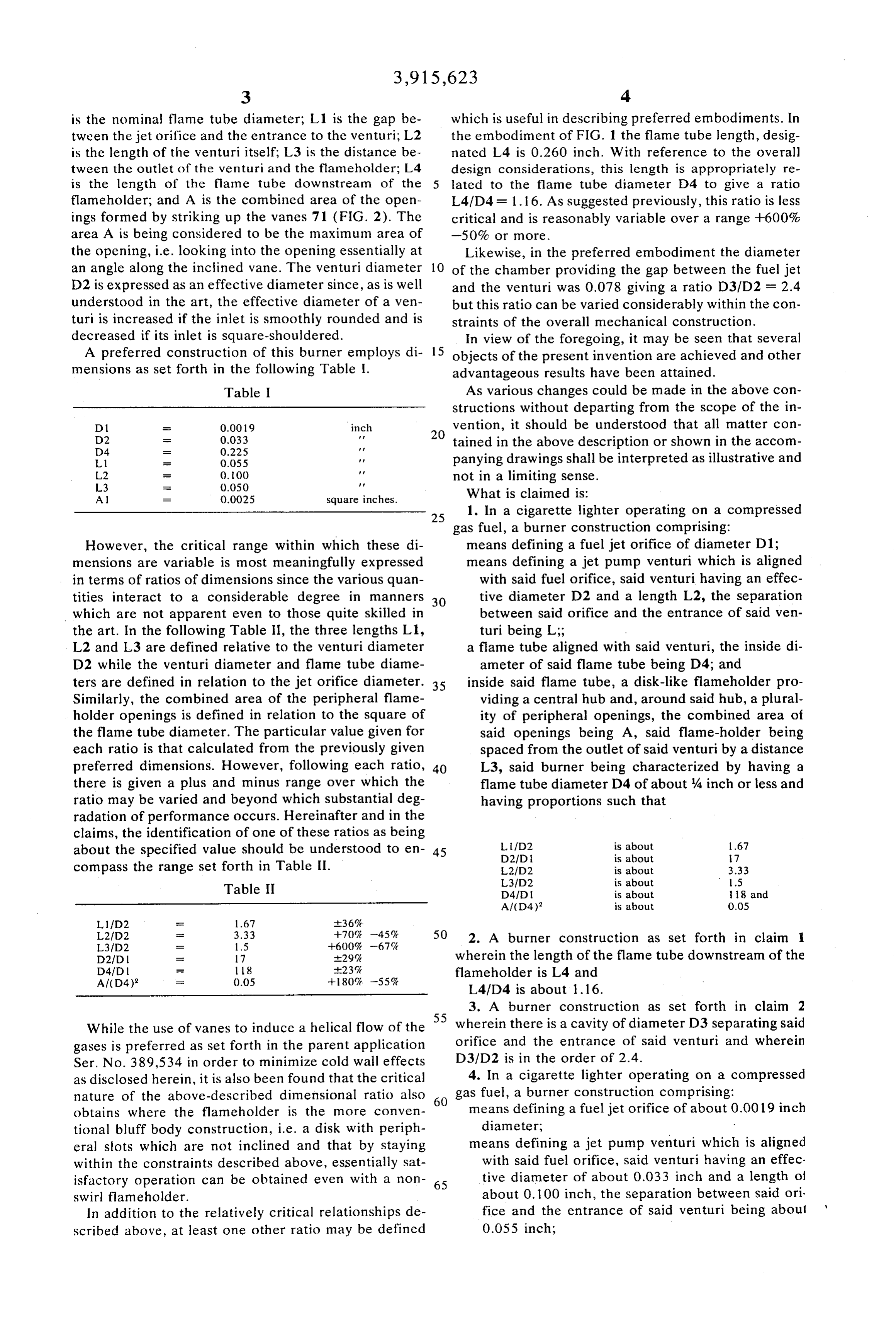
obtains where the flameholder is the more conven means defining a fuel jet orifice of about 0.0019 inch tional bluff body construction, i.e. a disk with periph diameter, eral slots which are not inclined and that by staying means defining a jet pump venturi which is aligned within the constraints described above, essentially Sat with said fuel orifice, said venturi having an effec isfactory operation can be obtained even with a non 65 tive diameter of about 0.033 inch and a length of swirl flame holder. about 0.100 inch, the separation between said ori In addition to the relatively critical relationships de fice and the entrance of said venturi being about scribed above, at least one other ratio may be defined 0.055 inch;
Page 5
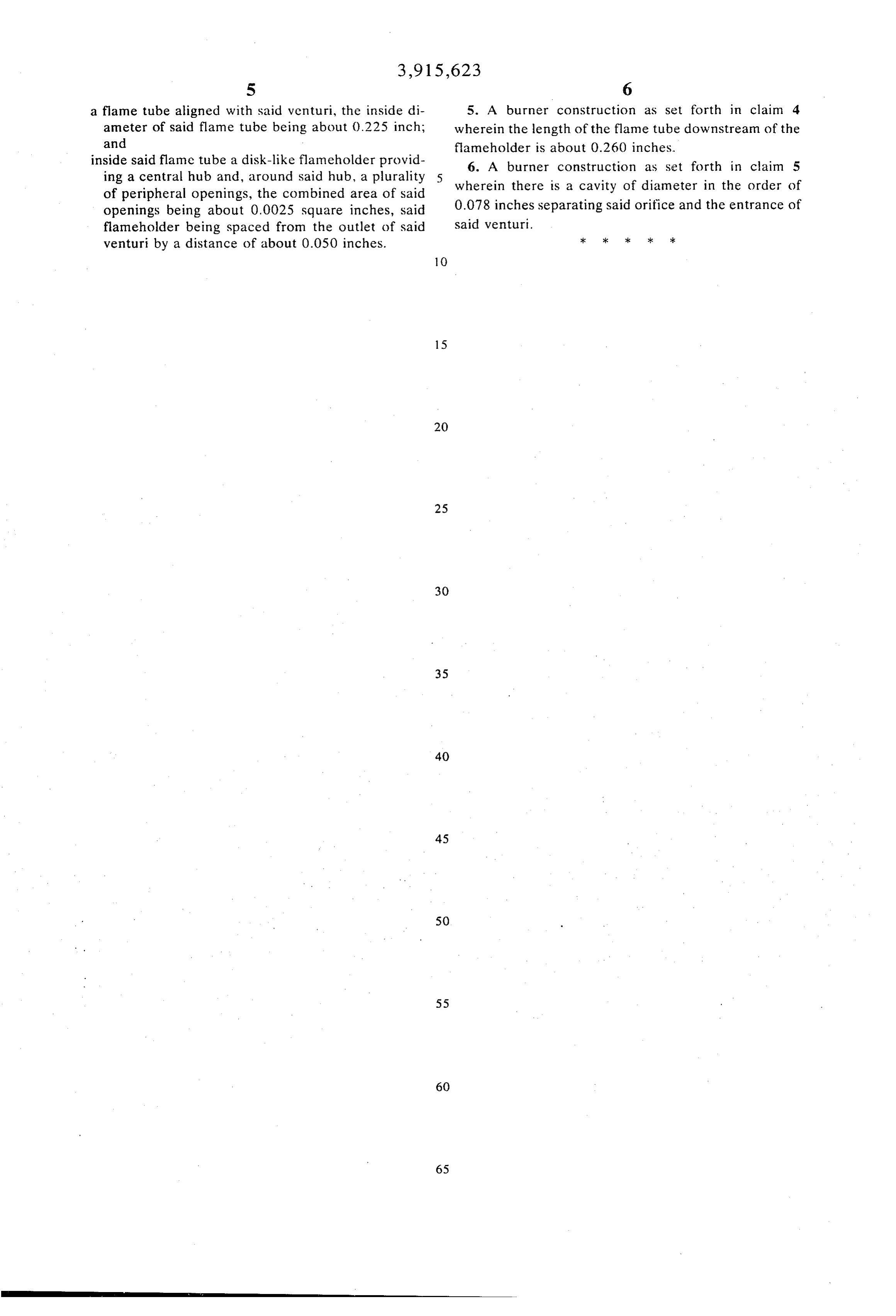
S 6 a flame tube aligned with said venturi, the inside di 5. A burner construction as set forth in claim 4 ameter of said flame tube being about 0.225 inch; wherein the length of the flame tube downstream of the and fame holder is about 0.260 inches. inside said flame tube a disk-like flameholder provid 6. A burner construction as set forth in claim 5 ing a central hub and, around said hub, a plurality wherein there is a cavity of diameter in the order of of peripheral openings, the combined area of said openings being about 0.0025 square inches, said 0.078 inches separating said orifice and the entrance of flameholder being spaced from the outlet of said said venturi.
venturi by a distance of about 0.050 inches.
Provenance
- Collection
- Cited prior art
- Original PDF
- patentimages.storage.googleapis.com →
- Filed
- 1974-09-06
- Pages
- 5
- Method
- pdftotext (the PDF's own text layer) + pdftoppm 300dpi page scans
- Source
- Google Patents bibliographic record
- Granted
- 1975-10-28
- Inventors
- Alex F Wormser; Wingaersheek Inc
- Transcribed from
- patentimages.storage.googleapis.com →