patent · US4538530
Burner for the suspension firing of comminuted material
3 September 1985
Page 1 — bibliographic record
United States Patent (19) 11) Patent Number: 4,538,530 Whitman 45. Date of Patent: Sep. 3, 1985 54) BURNER FOR THE SUSPENSION FIRING the combustible material expanding in a circular pat OF COMMINUTED MATERIAL tern. Inside of this circular pattern there is an outwardly 76 Inventor: John E. Whitman, 921 Lakeridge directed flame to contact the combustible material. The Dr., Olympia, Wash. 98502 result is an immediate ignition of the combustible mate 21) Appl. No.: 108,584 rial and the complete burning of the combustible mate rial. There is also a refractory near the burner head.
22 Filed: Dec. 31, 1979 After the refractory has been heated to a desired tem 51) Int. Cl............................. F23C 1/02; F23C 1/04 perature the outwardly directed flame can be discontin 52 U.S.C. .................................... 110/260; 110/244; ued and the heat energy from the refractory material is 110/263; 110/346; 110/347; 431/284; 431/285; sufficient to assist in the immediate firing of the combus 431/347 tible material. A result of this is that an auxiliary fuel 58) Field of Search ............... 110/260, 261, 252, 263, such as fuel oil or natural gas is not required, after the 110/264, 265, 347, 244, 346; 431/284, 285, 8, 9, refractory has reached the desired temperature to sus 347 tain combustion of the combustible material. Further, 56) References Cited with the complete burning of the combustible material there is less possibility of particulate matter being intro
3,830,172 8/1974 Hindenlang..................... 10/244 X possibility of particulate matter condensing out on 3,837,303 9/1974 Baardson ............................. 110/244 boiler tubes in a furnace. Another factor of this inven 4,021,188 5/1977 Yamagisai et al. ............... 43/10 X tion is that the burner head and supporting equipment Primary Examiner-Edward G. Favors can be removed from the hot furnace and repaired out side the hot furnace or another burner head can be
Attorney, Agent, or Firm-Thomas W. Secrest introduced into the hot furnace. This means that it is not (57) ABSTRACT necessary to cool the hot furnace before working on the This invention is directed to the suspension firing of a burner head.
comminuted combustible material and the supporting structure for such suspension firing. The combustible material is introduced to a burner head which results in 12 Claims, 10 Drawing Figures
Page 2
Drawing sheet — no readable text.
Page 3
Drawing sheet — no readable text.
Page 4
Drawing sheet — no readable text.
Page 5
Drawing sheet — no readable text.
Page 6
Drawing sheet — no readable text.
Page 7
veying the flammable gas inside of the middle size tube
BURNER FOR THE SUSPENSION FRING OF for conveying the cooling air and illustrates the middle COMMINUTED MATERIAL size tube positioned by centering means inside of the
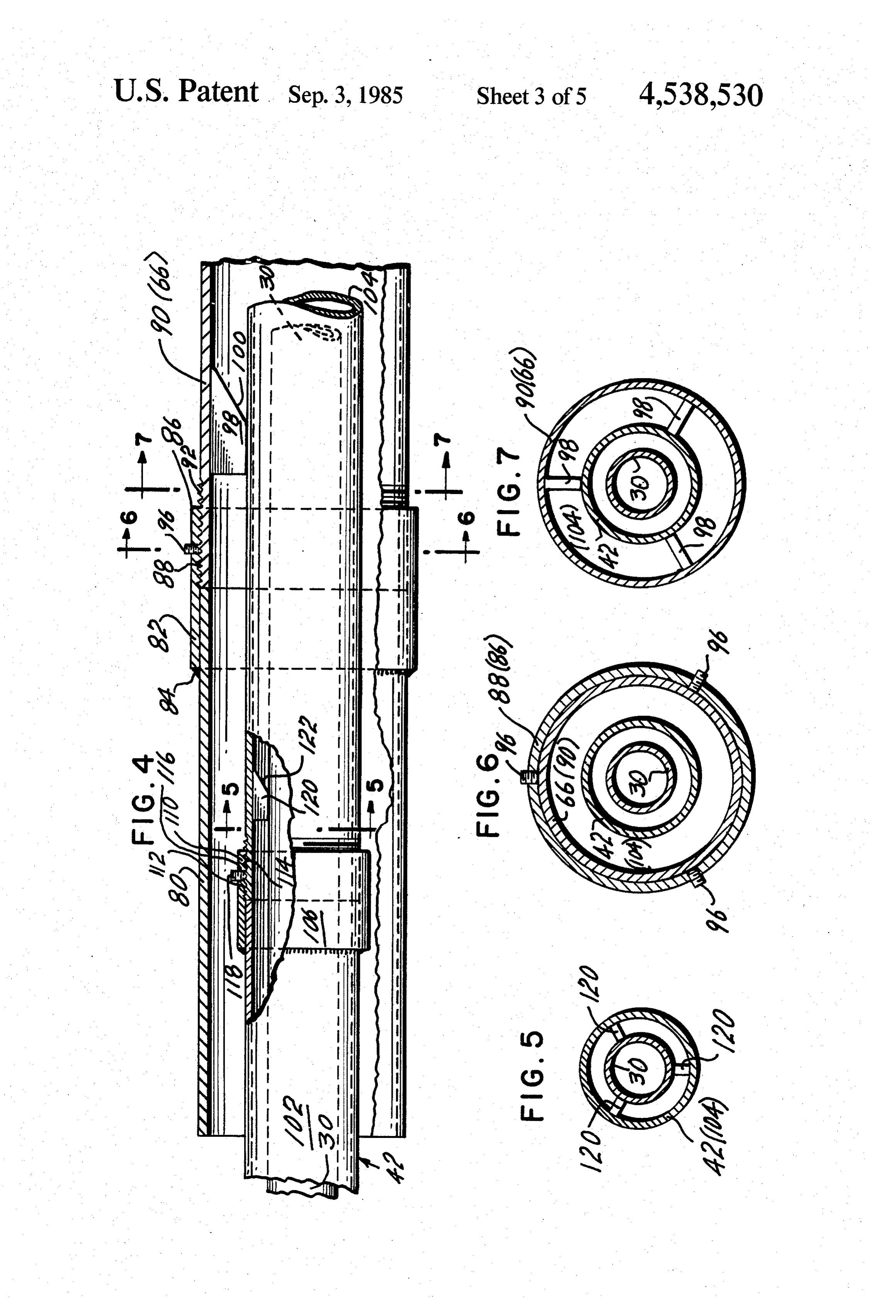
largest tube for conveying the comminuted material which will undergo combustion;
This invention is for the suspension burning of com FIG. 5, taken on Line 5-5 of FIG. 4, is a lateral minuted combustible materials, such as cellulose based cross-sectional view illustrating the centering means for products or rubber based products, in any direct fired centering the smallest tube for conveying the flammable heat exchanger such as a boiler furnace or a rotary kiln. O gas inside of the middle size tube for conveying the There is a burner head which diffuses or mixes the cooling air;
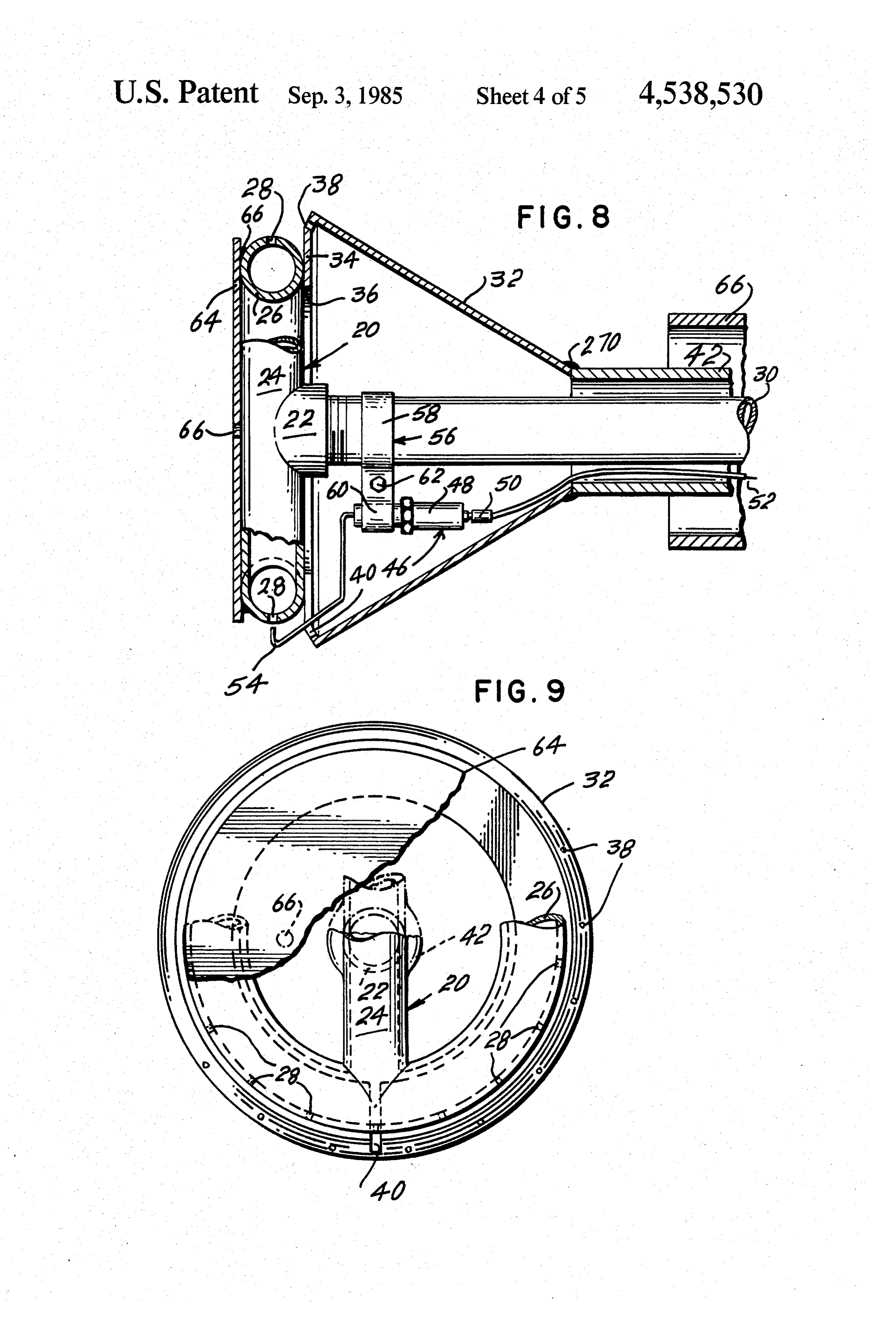
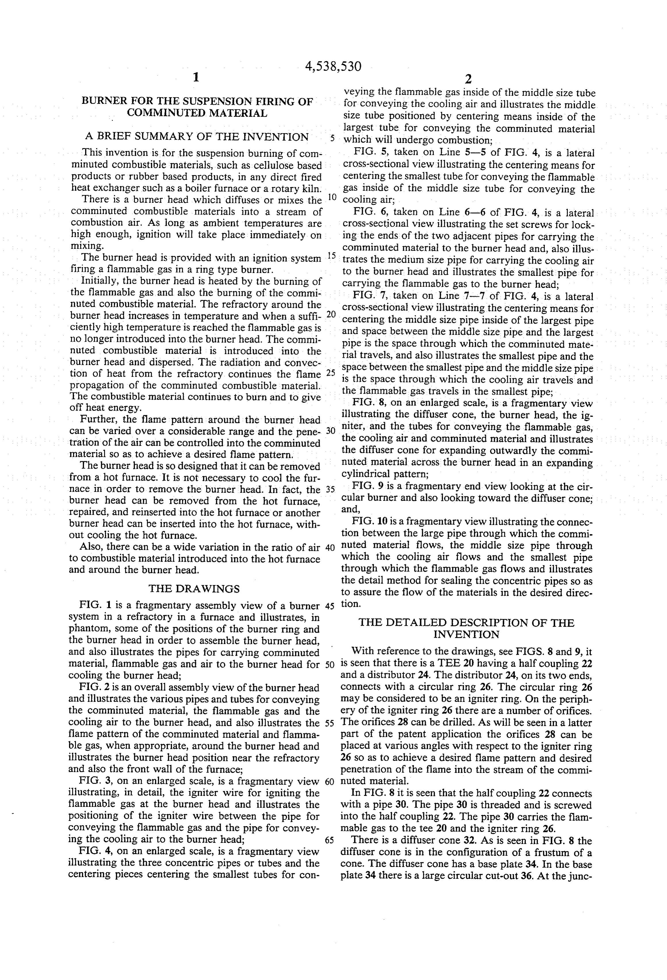
comminuted combustible materials into a stream of FIG. 6, taken on Line 6-6 of FIG. 4, is a lateral combustion air. As long as ambient temperatures are cross-sectional view illustrating the set screws for lock high enough, ignition will take place immediately on ing the ends of the two adjacent pipes for carrying the mixing. comminuted material to the burner head and, also illus The burner head is provided with an ignition system trates the medium size pipe for carrying the cooling air firing a flammable gas in a ring type burner. to the burner head and illustrates the smallest pipe for Initially, the burner head is heated by the burning of carrying the flammable gas to the burner head; the flammable gas and also the burning of the commi FIG. 7, taken on Line 7-7 of FIG. 4, is a lateral nuted combustible material. The refractory around the cross-sectional view illustrating the centering means for burner head increases in temperature and when a suff- 20 centering the middle size pipe inside of the largest pipe ciently high temperature is reached the flammable gas is and no longer introduced into the burner head. The commi pipe space is the between the middle size pipe and the largest space through which the comminuted mate nuted combustible material is introduced into the rial burner head and dispersed. The radiation and convec space between travels, and also illustrates the smallest pipe and the tion of heat from the refractory continues the flame 25 is the space through the smallest pipe and the middle size pipe propagation of the comminuted combustible material. the flammable gas travels which the cooling air travels and The combustible material continues to burn and to give in the smallest pipe; off heat energy. FIG. 8, on an enlarged scale, is a fragmentary view Further, the flame pattern around the burner head niter, illustrating the diffuser cone, the burner head, the ig can be varied over a considerable range and the pene-30 the cooling and the tubes for conveying the flammable gas, tration of the air can be controlled into the comminuted air and comminuted material and illustrates material so as to achieve a desired flame pattern. the diffuser cone for expanding outwardly the commi The burner head is so designed that it can be removed nuted material across the burner head in an expanding from a hot furnace. It is not necessary to cool the fur cylindrical pattern;
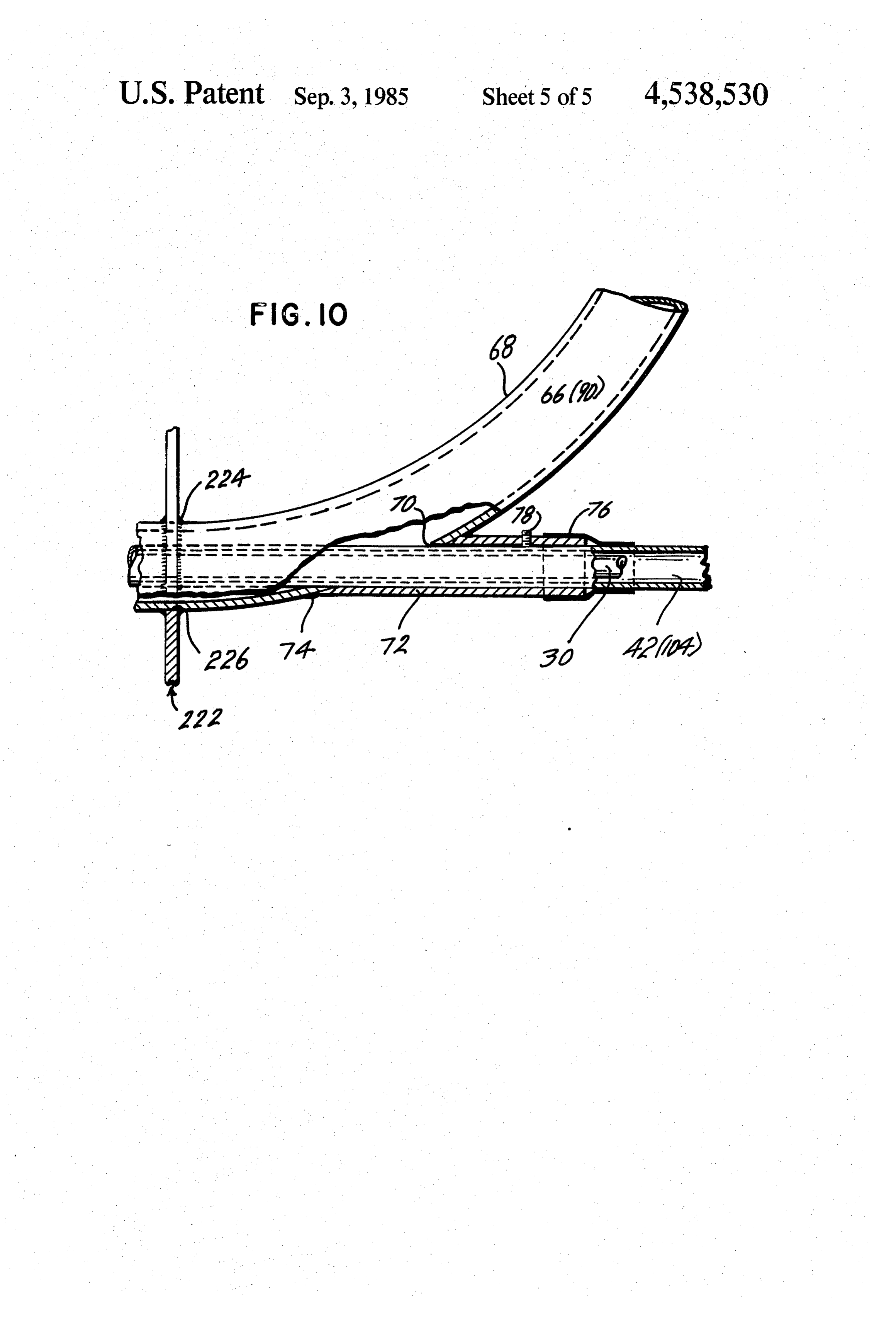
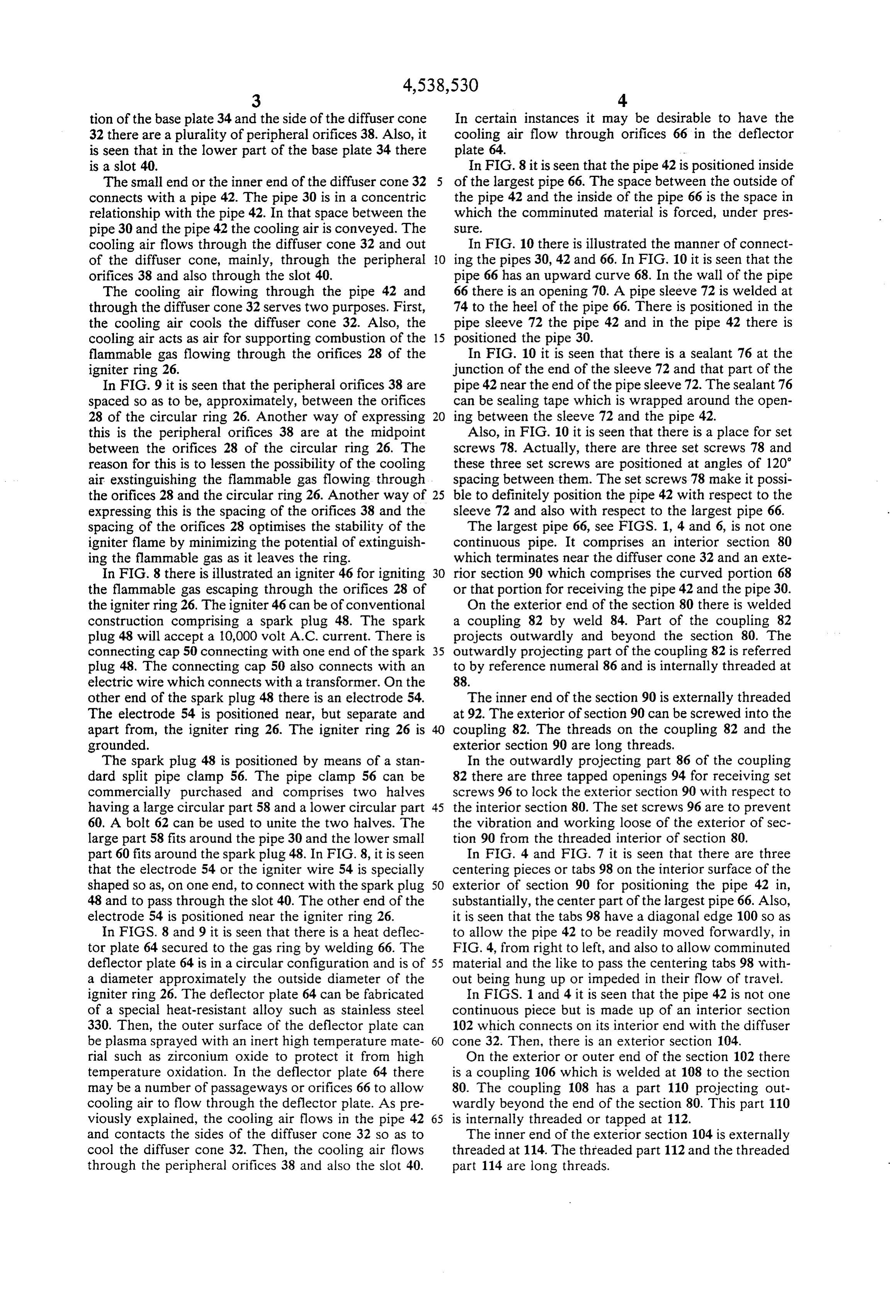
nace in order to remove the burner head. In fact, the 35 FIG. 9 is a fragmentary end view looking at the cir burner head can be removed from the hot furnace, cular burner and also looking toward the diffuser cone; repaired, and reinserted into the hot furnace or another and, burner head can be inserted into the hot furnace, with FIG. 10 is a fragmentary view illustrating the connec out cooling the hot furnace. tion between the large pipe through which the commi Also, there can be a wide variation in the ratio of air 40 nuted material flows, the middle size pipe through to combustible material introduced into the hot furnace which the cooling air flows and the smallest pipe and around the burner head. through which the flammable gas flows and illustrates
THE DRAWINGS
the detail method for sealing the concentric pipes so as to assure the flow of the materials in the desired direc
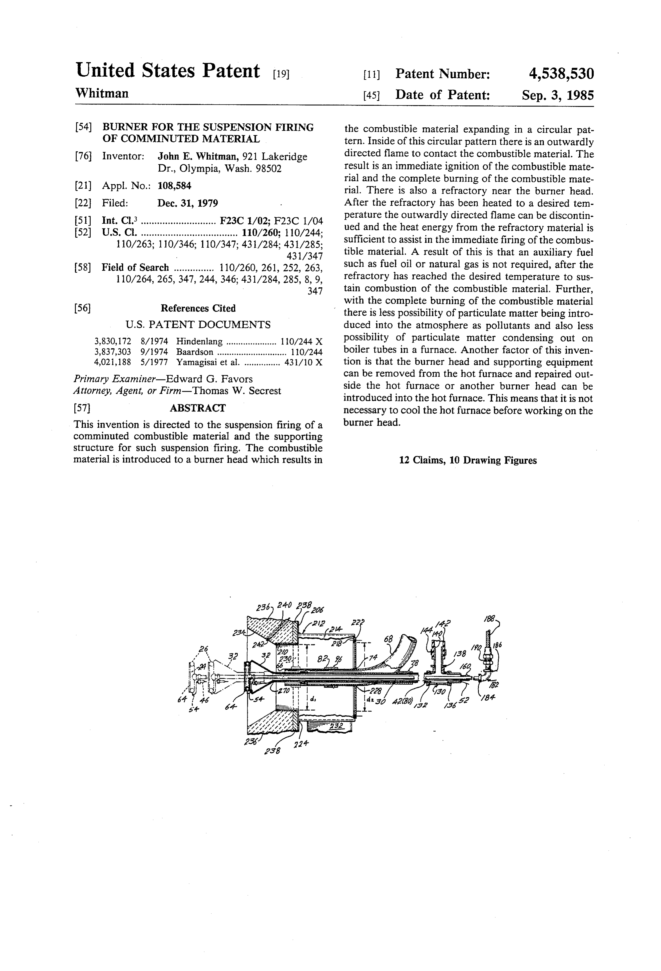
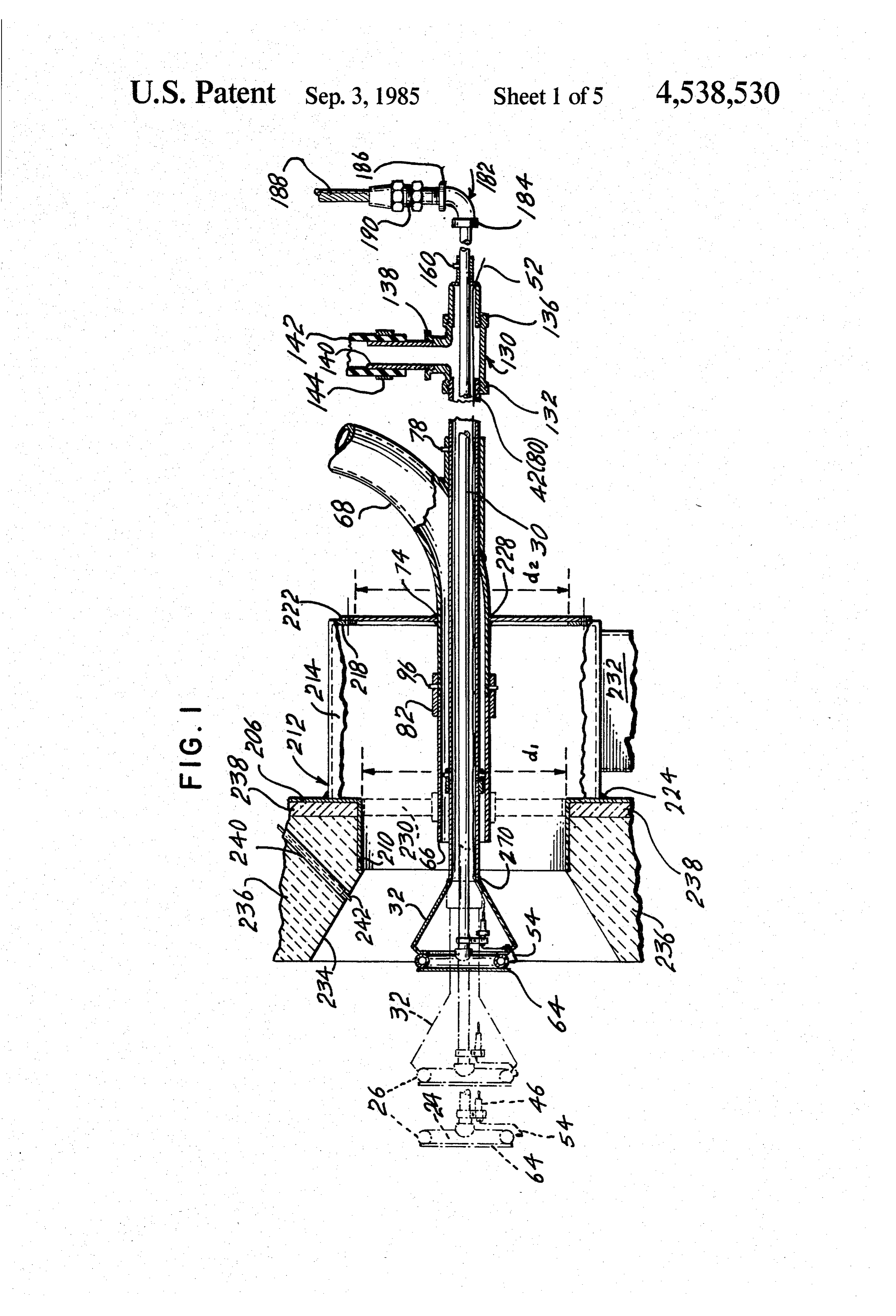
FIG. 1 is a fragmentary assembly view of a burner 45 tion.
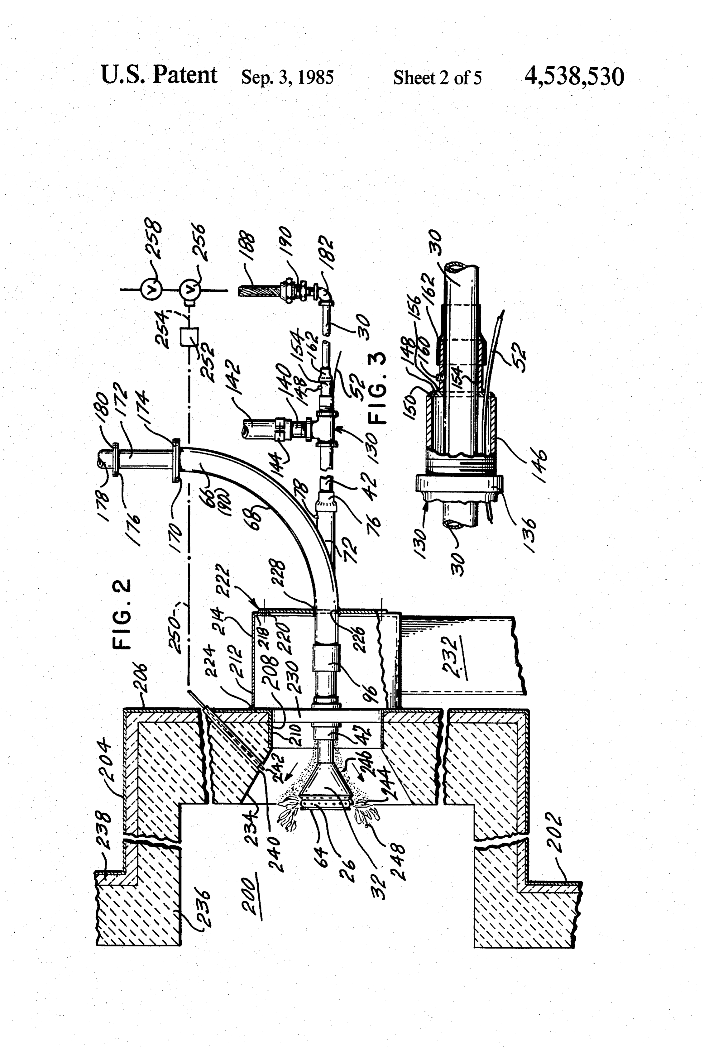
system in a refractory in a furnace and illustrates, in THE DETAILED DESCRIPTION OF THE phantom, some of the positions of the burner ring and INVENTION the burner head in order to assemble the burner head, and also illustrates the pipes for carrying comminuted With reference to the drawings, see FIGS. 8 and 9, it material, flammable gas and air to the burner head for 50 is seen that there is a TEE 20 having a half coupling 22 cooling the burner head; and a distributor 24. The distributor 24, on its two ends, FIG. 2 is an overall assembly view of the burner head connects with a circular ring 26. The circular ring 26 and illustrates the various pipes and tubes for conveying may be considered to be an igniter ring. On the periph the comminuted material, the flammable gas and the ery of the igniter ring 26 there are a number of orifices. cooling air to the burner head, and also illustrates the 55 The orifices 28 can be drilled. As will be seen in a latter flame pattern of the comminuted material and flamma part of the patent application the orifices 28 can be ble gas, when appropriate, around the burner head and placed at various angles with respect to the igniter ring illustrates the burner head position near the refractory 26 so as to achieve a desired flame pattern and desired and also the front wall of the furnace; penetration of the flame into the stream of the commi FIG. 3, on an enlarged scale, is a fragmentary view 60 nuted material.
illustrating, in detail, the igniter wire for igniting the In FIG. 8 it is seen that the half coupling 22 connects flammable gas at the burner head and illustrates the with a pipe 30. The pipe 30 is threaded and is screwed positioning of the igniter wire between the pipe for into the half coupling 22. The pipe 30 carries the flam conveying the flammable gas and the pipe for convey mable gas to the tee 20 and the igniter ring 26. ing the cooling air to the burner head; 65 There is a diffuser cone 32. As is seen in FIG. 8 the FIG. 4, on an enlarged scale, is a fragmentary view diffuser cone is in the configuration of a frustum of a illustrating the three concentric pipes or tubes and the cone. The diffuser cone has a base plate 34. In the base centering pieces centering the smallest tubes for con plate 34 there is a large circular cut-out 36. At the junc
Page 8
tion of the base plate 34 and the side of the diffuser cone In certain instances it may be desirable to have the 32 there are a plurality of peripheral orifices 38. Also, itcooling air flow through orifices 66 in the deflector is seen that in the lower part of the base plate 34 there plate 64.
is a slot 40. In FIG. 8 it is seen that the pipe 42 is positioned inside The small end or the inner end of the diffuser cone 32 5 of the largest pipe 66. The space between the outside of connects with a pipe 42. The pipe 30 is in a concentric the pipe 42 and the inside of the pipe 66 is the space in relationship with the pipe 42. In that space between the which the comminuted material is forced, under pres pipe 30 and the pipe 42 the cooling air is conveyed. The S.
cooling air flows through the diffuser cone 32 and out In FIG. 10 there is illustrated the manner of connect of the diffuser cone, mainly, through the peripheral 10 ing the pipes 30, 42 and 66. In FIG. 10 it is seen that the orifices 38 and also through the slot 40. pipe 66 has an upward curve 68. In the wall of the pipe The cooling air flowing through the pipe 42 and 66 there is an opening 70. A pipe sleeve 72 is welded at through the diffuser cone 32 serves two purposes. First, 74 to the heel of the pipe 66. There is positioned in the the cooling air cools the diffuser cone 32. Also, the pipe sleeve 72 the pipe 42 and in the pipe 42 there is cooling air acts as air for supporting combustion of the 15 positioned the pipe 30.
flammable gas flowing through the orifices 28 of the In FIG. 10 it is seen that there is a sealant 76 at the igniter ring 26. junction of the end of the sleeve 72 and that part of the In FIG. 9 it is seen that the peripheral orifices 38 are pipe 42 near the end of the pipe sleeve 72. The sealant 76 spaced so as to be, approximately, between the orifices can be sealing tape which is wrapped around the open 28 of the circular ring 26. Another way of expressing 20 ing between the sleeve 72 and the pipe 42. this is the peripheral orifices 38 are at the midpoint Also, in FIG. 10 it is seen that there is a place for set between the orifices 28 of the circular ring 26. The screws 78. Actually, there are three set screws 78 and reason for this is to lessen the possibility of the cooling these three set screws are positioned at angles of 120 air exstinguishing the flammable gas flowing through spacing between them. The set screws 78 make it possi the orifices 28 and the circular ring 26. Another way of 25 ble to definitely position the pipe 42 with respect to the expressing this is the spacing of the orifices 38 and the sleeve 72 and also with respect to the largest pipe 66. spacing of the orifices 28 optimises the stability of the The largest pipe 66, see FIGS. 1, 4 and 6, is not one igniter flame by minimizing the potential of extinguish continuous pipe. It comprises an interior section 80 ing the flammable gas as it leaves the ring. which terminates near the diffuser cone 32 and an exte In FIG. 8 there is illustrated an igniter 46 for igniting 30 rior section 90 which comprises the curved portion 68 the flammable gas escaping through the orifices 28 of or that portion for receiving the pipe 42 and the pipe 30. the igniter ring 26. The igniter 46 can be of conventional On the exterior end of the section 80 there is welded construction comprising a spark plug 48. The spark a coupling 82 by weld 84. Part of the coupling 82 plug 48 will accept a 10,000 volt A.C. current. There is projects outwardly and beyond the section 80. The connecting cap 50 connecting with one end of the spark 35 outwardly projecting part of the coupling 82 is referred plug 48. The connecting cap 50 also connects with an to by reference numeral 86 and is internally threaded at electric wire which connects with a transformer. On the 88.
other end of the spark plug 48 there is an electrode 54. The inner end of the section 90 is externally threaded The electrode 54 is positioned near, but separate and at 92. The exterior of section 90 can be screwed into the apart from, the igniter ring 26. The igniter ring 26 is 40 coupling 82. The threads on the coupling 82 and the grounded. exterior section 90 are long threads. The spark plug 48 is positioned by means of a stan In the outwardly projecting part 86 of the coupling dard split pipe clamp 56. The pipe clamp 56 can be 82 there are three tapped openings 94 for receiving set commercially purchased and comprises two halves screws 96 to lock the exterior section 90 with respect to having a large circular part 58 and a lower circular part 45 the interior section 80. The set screws 96 are to prevent 60. A bolt 62 can be used to unite the two halves. The the vibration and working loose of the exterior of sec large part 58 fits around the pipe 30 and the lower small tion 90 from the threaded interior of section 80. part 60 fits around the spark plug 48. In FIG. 8, it is seen In FIG. 4 and FIG. 7 it is seen that there are three that the electrode 54 or the igniter wire 54 is specially centering pieces or tabs 98 on the interior surface of the shaped so as, on one end, to connect with the spark plug 50 exterior of section 90 for positioning the pipe 42 in, 48 and to pass through the slot 40. The other end of the substantially, the center part of the largest pipe 66. Also, electrode 54 is positioned near the igniter ring 26. it is seen that the tabs 98 have a diagonal edge 100 so as In FIGS. 8 and 9 it is seen that there is a heat defec to allow the pipe 42 to be readily moved forwardly, in tor plate 64 secured to the gas ring by welding 66. The FIG. 4, from right to left, and also to allow comminuted deflector plate 64 is in a circular configuration and is of 55 material and the like to pass the centering tabs 98 with a diameter approximately the outside diameter of the out being hung up or impeded in their flow of travel. igniter ring 26. The deflector plate 64 can be fabricated In FIGS. 1 and 4 it is seen that the pipe 42 is not one of a special heat-resistant alloy such as stainless steel continuous piece but is made up of an interior section 330. Then, the outer surface of the deflector plate can 102 which connects on its interior end with the diffuser be plasma sprayed with an inert high temperature mate- 60 cone 32. Then, there is an exterior section 104. rial such as zirconium oxide to protect it from high On the exterior or outer end of the section 102 there temperature oxidation. In the deflector plate 64 there is a coupling 106 which is welded at 108 to the section may be a number of passageways or orifices 66 to allow 80. The coupling 108 has a part 110 projecting out cooling air to flow through the deflector plate. As pre wardly beyond the end of the section 80. This part 110 viously explained, the cooling air flows in the pipe 42 65 is internally threaded or tapped at 112. and contacts the sides of the diffuser cone 32 so as to The inner end of the exterior section 104 is externally cool the diffuser cone 32. Then, the cooling air flows threaded at 114. The threaded part 112 and the threaded through the peripheral orifices 38 and also the slot 40. part 114 are long threads.
Page 9
The exterior section 104 is screwed into the coupling 176 are united so as to be flush and tight with respect to so as to abut against the end of the interior section 102. each other.
The purpose of the long threads is to allow the two The flanges 170 and 174 and the flanges 176 and 180 sections of pipe to be screwed together with the ends can be united with conventional means. For example, abutting against each other so that there is not a void or 5 these flanges can be bolted and gasketed together. a lapse between the two ends of the two sections of It is to be noted that the diameter of the pipe 172 is pipe. smaller than the diameter of the pipe 66 or the exterior In the outwardly projecting part 110 of the coupling section 90. The reason for this is to have substantially there are three tapped openings 116. In these tapped the same conveying area or cross-sectional area in the openings 116 are set screws for bearing against the outer O pipe 172 as in the pipe 66 less the cross-sectional area surface of the outer section 104 so as to definitely posi taken by the pipe 42 inside the pipe 66. Another way of tion the pipe 104. This definite positioning of the pipe expressing this is to say that the largest pipe 66 is larger 104 means that with vibration the pipe will not become in cross-sectional area than the pipe 172 so as to com unthreaded or unscrewed from the coupling and move pensate for the cross-sectional area taken up by the away from the end of the pipe 102. 15 cooling pipe 42.
In FIGS. 4 and 5 there is illustrated three centering There is an elbow 182 having a first tapped end 184. pieces or three tabs 120. These tabs, substantially, posi The outer end of the smallest pipe 30 has a tapped end tion the pipe 30 in the central part of the pipe 43. Again, and is screwed into the first tapped end 184. Also, the it is noted that the tabs have a leading diagonal edge for elbow 182 has a second tapped end 186. ease of moving the pipe 30 forwardly and into the pipe 20 There is a flexible metal hose 188 having a union 42. Again, that space between the pipe 30 and the pipe adapter fitting 190 which is threaded on its outer end for 42 is for conveying air, which functions as a cooling gas screwing into the second tapped end 186 of the elbow as well as supporting combustion. 182.
With reference to the pipes 30, 42 and 66 the reader is The largest pipe 66 connects with the source of com referred to FIGS. 1, 2 and 3. In these figures it is seen 25 bustible comminuted material. This comminuted mate that there is a TEE 130 having a first tapped end 132. rial is forced under pressure through the pipe 66 and The middle size pipe 42, in particular, of the outer sec around the pipe 42 so as to contact the outer surface of tion 80, is threaded at 134 so as to be screwed into the the diffuser cone 32. The pressure in the largest pipe 66, tee 130. as the comminuted material approaches the diffuser The TEE 130 has a second tapped end 136 and a 30 cone 32, can be in the neighborhood of one pound posi tapped third end 138. tive pressure.
There is screwed into the tapped third end 138 a The flexible hose 142 connects with the source of air. threaded pipe 140. The threaded pipe receives a flexible The air pressure of the air in the flexible hose 142 may hose 142. The flexible hose is positioned on the pipe 140 be in the range of one or two inches of water. This is a, by means of a clamp 144. 35 relatively, low pressure.
There is a threaded pipe nipple 146 which is screwed The flexible metal hose 188 connects with the source into the second tapped end 136 of the tee 130. On the of combustible gas such as liquified petroleum gas or outer end of the nipple 146 there is a reducing plate 148. natural gas or water gas. The pressure of the gas in the The reducing plate 148 is welded to the nipple 146 by flexible metal hose will vary depending upon the type of weld 150. 40 gas used and the heat output of the igniter ring 26. The In the center part of the plate 148 there is an opening pressure of the gas in the flexible metal hose 188 will be 152 for receiving the smallest pipe 30. adjusted depending upon the availability and type of There is welded a sleeve 154, at weld 156, to the outer combustible gas or flammable gas. surface of the reducing plate 148. In the sleeve 154 are In FIGS. 1 and 2 there is illustrated a heat exchanger three tapped openings 158 for receiving set screws 160 45 200 such as a furnace or a kiln. The furnace 200 has a to definitely position the smallest pipe 30 in the sleeve shell or supporting metal structure comprising a front 154. The purpose of the set screws 160 is to position the wall 202 and an outwardly projecting support 204. smallest pipe 30, axially, with respect to the pipe 42 and Then, there is a front wall 206, in FIGS. 1 and 2, to the also with respect to the diffuser cone 32. Again, the right of the outwardly projecting support 204 and form purpose of the set screws 160 is to axially position the 50 ing part of the shell or supporting metal structure. smallest pipe 30 within the middle size pipe 42 so as to In the front wall 206 there is an opening 208. Project also position the igniter ring 26 against the base plate 34 ing inwardly from the opening 208 and towards the of the diffuser cone 32. front wall 202 there is a supporting structure 210. There is a sealant 162 wrapping around the outer end There is a wind box. 212 or plenum 212 on the outside of the sleeve 154 and the adjoining outer surface of the 55 of the front wall 206. This wind box or plenum 212 can smaller pipe 30. The sealant 164 can be a tape such as a comprise a circular or rectangular housing 214. The plastic tape commonly used in the construction indus housing 214 comprises a front wall 218. In the front wall try. 218 there is an opening 220.
In the reducing plate 148 there is an opening 164. The There is a closure plate 222 covering the opening 220. electric wire or igniter wire 52 passes through said 60 The closure plate 222 may be attached to the plenum opening 164 and to the spark plug 48. 212 by means of bolts connecting the closure plate 222 In FIG. 2 it is seen that the largest pipe 66, in particu with the front wall 218.
lar, the exterior section 90, terminates in a flange 170. The wind box. 212 or plenum 212 is connected to the There is a pipe 172 which has a reducing flange 174 on front wall 206 by a weld 224 or, in the alternative, can its lower end and a flange 176 on its upper end. The 65 be bolted depending upon the circumstances. flanges 170 and 174 are united so as to be flush and tight In the closure plate 222 there is an opening 226. The with respect to each other. Then, there is a pipe 178 largest pipe 66 projects through the opening 226 and is which has a flange 180. The flange 180 and the flange attached to the closure plate 222 by weld 228. There is
Page 10
an air diffuser 230 which is secured to the largest pipe 66 opinion, means that far less gas is needed to initiate and can be placed in the opening 208. The purpose of combustion of the comminuted combustible material as the air diffuser is to impart rotation to the air entering compared with the instance where an external gas ring, into the heat exchanger 200 so that the air will mix more to the flow pattern of the comminuted combustible rapidly with the comminuted combustible material material, is used. By a gas ring which is external to the being introduced into the heat exchanger. The reader is flow pattern of the combustible material I mean that this to understand that in many instances it is not necessary ring is directing flammable gas inwardly and that the to have an air diffuser 230. In certain installations it its combustible material flows inside of this external ring. I desirable to have an air diffuser 230 but in other installa consider that this internal igniter ring 26 is superior to a tions the air diffuser 230 is not required. 10 point flame as there is a more complete diffusion of the There is an air duct 232 connecting with the lower flame, from the flammable gas, into the stream of the part of the plenum 212 so as to allow air to flow into the comminuted combustible material. I consider that this plenum 212 and then through the opening 208. The internal igniter ring is superior to a point flame or to a reader is to understand that the air duct 232 may con flame which is delivered to a very restricted part of the nect with the wind box. 212 at the top or side or any 15 dust stream or comminuted combustible material convenient location, depending upon the installation. stream. In contrast to the igniter ring of my invention it It is to be realized that the air duct 232 may connect is to be understood that when there is an igniter deliver with a fan for forcing air into the air duct 232 and then ing a flammable gas or a flame to a restricted area of the into the wind box 212. comminuted combustible material stream that there is The supporting structure 210 connects with a frustum 20 not, substantially, instantaneous combustion of the ma of a cone 234. The frustum of the cone expands out terial. It is to be realized that time is required for all of wardly from the supporting structure 210 as it goes the combustible material to come up to ignition temper towards the heat exchanger 200. The shape of the frus ature. The combustible material is being carried into the tum of the cone 234 is such as to radiate heat energy, at furnace but the combustible material has not completely a right angle or normal, to the surface of the diffuser 25 burned. It is, readily, understood that the sooner the cone 32. The surface of the frustum of the cone 234 is combustible material is ignited the more desirable the shaped so as to be parallel to the outer surface of the combustion process. It is apparent that the sooner the diffuser cone 32 so as to optimise the transfer of heat combustible material is ignited there is a greater amount energy by radiation from the surface of the cone 234 to of time for the combustible material to burn to comple the surface of the diffuser cone 32. 30 tion or to go to completion as contrasted with this when In many heat exchangers there is a refractory mate some or all of the combustible material is not immedi rial and an insulating block. It is to be understood that ately ignited there is a less period of time for the com not all heat exchangers have a refractory material or an bustible material to burn to completion and as a result of insulating block. As illustrated in FIGS. 1 and 2 there is this period of time there can be a release of excessive a refractory material 236 and an insulating block 238 35 particulates to the atmosphere; there could be an exces between the refractory material 236 and the shell or sive build-up of particulate matter on the exchanger supporting metal structure. surfaces; and, there have been instances where the In FIGS. 1 and 2 it is seen that there is an outwardly build-up or accumulation of combustibles in the heat projecting support 204. exchanger have subsequently resulted in an explosion. It is seen that there is a passageway 240 leading from In FIGS. 1 and 2 it is seen that the flame pattern of the the frustum of the cone to the exterior of the outwardly combustible gas is referred to by reference numeral 244 projecting support 204 and through the front wall 206. and that the flow of the comminuted combustible mate A thermocouple 242 can be placed in this passageway rial as referred to by reference numeral 246. At the 240 so as to monitor the temperature in the vicinity of meeting place or intersection of the flammable gas 244 the frustum of the cone 234 and the diffuser cone 32. 45 and the comminuted material 246 there results a flame The thermocouple 242 serves a useful purpose as it pattern 248. In FIG. 2 it is seen that the combustible allows a monitor to sense the temperature around the material 246 flows into the flame 244 so as to be ignited frustum of the cone 234 and the diffuser cone 32. Upon and there results a flame pattern which fully encom starting the burner in a cold furnace the flammable gas passes the diffuser cone 32 on a 360 basis. This insures is introduced through the pipe 30 to the igniter ring 26. 50 an immediate ignition of the combustible materials so as The flammable gas is ignited. Then, comminuted corn to have the maximum time possible to complete burn bustible material may be introduced through the largest out of the combustible material. The flammable gas is pipe 66 so as to flow past the surface of the diffuser cone used when the heat exchanger 200 is cold and the ambi 32. The comminuted combustible material upon flowing ent temperature surrounding the diffuser cone 32 is too past the surface of the diffuser cone 32 is expanded 55 low to fully ignite all of the combustible material enter outwardly and in an outwardly expanding circular pat ing into the frustum of the cone 234 and surrounding the tern. The position of the igniter ring 26 is near the outer diffuser cone 32. When the ambient temperature is too end or the base of the diffuser cone 32 and inside the low to insure full combustion of the combustible mate expanding circular pattern of the combustible material. rial, such as in start-up of a cold heat exchanger, it is The flammable gas from the igniter ring 26 contacts the 60 necessary to use the flammable gas and the igniter ring comminuted combustible material so as to ignite this 26.
material. The reader is to realize that the flammable gas The monitor or the person looking after the furnace from the igniter ring 26 expands outwardly over a 360' can use the thermocouple to determine when the ambi pattern. This flammable gas expanding outwardly over ent temperature conditions in area of the cone 234 and the 360 pattern contacts the comminuted combustible 65 the diffuser cone 32 are high enough to initiate combus material which is also expanding outwardly. The result tion of all of the comminuted combustible material then of the flammable gas being inside of the circular flow the monitor can discontinue the use of flammable gas pattern of the comminuted combustible material, in my and the igniter ring 26. The monitor can be an operating
Page 11
personnel for the furnace. In certain instances, instead view in FIG. 1. The igniter ring 26 and the pipe 42 are of using a human being, the monitor may be an electri tightly screwed together so as to prevent the leaking of cal-mechanical device or any other suitable device can flammable gas at the junction of the two. be used to terminate the flow of flammable gas to the The next step is to secure the spark plug 48 adjacent igniter ring 26 when favorable ambient conditions pre to the end of the pipe 42 and near the igniter ring 26 vail. until the proper positioning of the electrode 54 is An automatic control is, schematically, illustrated in acheived with respect to the igniter ring 26. This is FIG. 2. It is seen that there is a line 250 connecting with accomplished by means of the pipe clamp 56. With the thermocouple 242. The line 250 also connects with proper positioning the bolt is tightened and the spark a signal conversion relay 252. The signal conversion 10 plug is definitely positioned with respect to the pipe 42 relay 252 connects by means of aligning 254 with the and the electrode 54 is definitely positioned with re valve 256. The valve 256 is in the incoming line 188. spect to the igniter ring 26.
The valve 256 can be used for shutting off the flow of The next step is to attach the electric wire 52 to the gas to the igniter ring 26 on signal from the conversion spark plug 48. After this has been accomplished the relay 252 and the thermocouple 242. Further, there may 15 igniter ring 26 can be moved towards the base 34 of the be a manual valve 258 in the line 188. An operator can diffuser cone 32. It is to be remembered that upon mov manually shut off the valve or open the valve 258 to ing the igniter ring 26 towards the base 34 the electrode allow the flow of flammable gas to the igniter ring 26. 54 must be positioned in the slot 40 in the base plate 34. The feature of being able to shut off the flow of flam Concurrent with the movement of the igniter ring 26 mable gas to the igniter ring, when favorable ambient 20 towards the base plate 34 it is necessary to retract the temperature conditions have been realized, means a electric wire igniter wire 52 in the pipe 42. considerable saving in the use of the flammable gas. As The igniter ring 26 is moved and positioned so that it most flammable gas is derived from petroleum or is a fits snug and tight against the exterior surface of the by-product from the petroleum fields, such as propane base plate 34. Then, the set screws 160 can be tightened and butane, there is a considerable saving in the use of 25 so as to definitely position the pipe 30 and the pipe 42 petroleum product or by-product. with respect to each other.
The components are not assembled and it is necessary It is to be recalled that the closure plate 222 is welded to assemble these components for use in the heat ex to the largest pipe 66. With respect to FIG. 2 that por changer 200. These components can be assembled out tion of the largest pipe 66, to the left of the closure plate side of the heat exchanger 200 and, if necessary, on an 30 222 and the diffuser cone 32 in the igniter ring 26 are adjoining floor. The components are designed to permit inserted through the opening 220 in the plenum 212. assembly outside of and away from the heat exchanger Then, the closure plate 222 can be bolted to the plenum 200. The place of assembly can be any convenient place 212.
such as a work bench or a floor. After the diffuser cone has been positioned with re The first step in the assembly is to secure the interior 35 spect to the end of the largest pipe 66 the three set section 80 to the exterior section 90 by screwing the two screws 78 can be tightened. The observer can observe together until the ends meet and then setting set screws the flame pattern. If the flame pattern is not the desired 96 to prevent rotation. one or is in the wrong position the observer can loosen The second step is to insert the cooling air pipe, exte the three set screws 78 and move the pipe 42 so as to rior section 104, through the pipe sleeve 72 and into the 40 adjust the position of the diffuser cone 32 with respect interior of the largest pipe 66. The insertion of the sec to the end of the largest pipe 66. Then, the three set tion 104 must be sufficient to clear the free end of the screws can again be tightened so as to definitely posi interior section 80 of the largest pipe 66. tion the diffuser cone with respect to the largest pipe 66. The diffuser cone 32 is attached, by welding, to the Previously, there has been mentioned the air diffuser interior section 102 so as to have an integral unit. Then, 45 230. It is possible to not attach the air diffuser 230 to the the interior section 102 and the exterior section 104 are largest pipe 66. In case it is desired to have the air dif screwed together so that the ends abut and touch each fuser 230 on the largest pipe 66 this must be attached other. Then the set screws 108 can be turned in so as to before the diffuser cone 32 in the interior section 102 is prevent rotation of the adjacent pipes. screwed onto the exterior section 104. The next step is to install the electric wire igniter wire 50 In order for this system to operate it is necessary to 52 through the opening 164 in the reducing plate 148 connect the flange 170 on the end of the largest pipe 66 and run that wire in the pipe 42 so that it extends into with the flange 174 of the pipe 172. This can be accom the diffuser cone 32. One way of accomplishing this is plished by bolting the two together. This assures a sup to insert a rigid wire into the opening 162 and run it in ply of comminuted combustible material to the heat the pipe 42 until it reaches the diffuser cone 32. It is to 55 exchanger 200.
be recalled that in the base plate 34 of the diffuser cone Also, the flexible hose 142 is positioned over the pipe 32 there is a large circular cut-out 36. The igniter wire 140 and the clamp 144 attached to securely position can be attached to the rigid wire and drawn through the together these two members.
opening 164 and into the cavity in the diffuser cone 32. Then, the union adapter fitting 190 can be screwed Then, the smallest pipe 30 can be inserted through the 60 into the second end 186 of the elbow 182 to securely opening 158 in the reducing plate 148 and inside of the position these two together.
pipe 42 until the end of this pipe extends beyond the Assume that the furnace is hot and operating and that base plate 34 of the diffuser cone 32. In other words, the it is desirable to remove the diffuser cone 32 and the end of the pipe 42 projects outwardly and beyond the igniter ring 26 from the heat exchanger 200. With my diffuser cone 32. This is shown in FIG. 1, see the ex 65 invention it is possible to remove the hot diffuser cone treme phantom view of the pipe 42 and the igniter ring, and the hot igniterring 26 from the heat exchanger 200. on the left. Then, the igniter ring 26 is screwed onto the This can be accomplished in the reverse manner to the end of the pipe 42, again, see the extreme left phantom assembly of the members. For example, the union
Page 12
adapter fitting adapter 190 can be unscrewed from ble material can burn then the particle size of the com elbow 182. The clamp 144 can be removed and the bustible material can be, relatively, large. However, if flexible hose 142 removed from the pipe 140. The the heat exchanger is a small heat exchanger and there flanges 174 and 170 can be disconnected so that the is only a short time in which the combustible material largest pipe 66 can be removed. Then, the closure plate can be burned then the combustible material must be of can be removed from the plenum 212 and the largest fine particle size, say, 16 minus mesh or a size of one pipe 66 of the diffuser cone 32 and the igniter ring millimeter or less.
moved out of the frustum of the cone 234, through the My burner and system optimises the potential for opening 208 and through the opening 220 and out onto initiating combustion of the material and thereby in the floor or to a work bench. After the diffuser cone 32 10 creases the probability that the combustible material and the igniter ring have cooled it is possible to do any will be completely burned. The maximum capability of required work. any suspension firing system is to provide for immediate With respect to FIG. 1 it is understood that the diam combustion of combustible material in the combustion eter of the opening, denoted by d2, is of a larger diame space. With my system I consider that my burner head, ter than the opening denoted by dil, 208 leading to the 15 in conjunction with the refractory, makes it possible to frustum of the cone 234. It is to be understood that the provide for immediate combustion of the combustible diameter of the opening d2 is always larger that the material.
diameter of the largest part of the assembly, in this case As previously stated there is the igniter ring 26 hav the diameter of the air diffuser 230 and the diameter of ing orifices 28 which direct the flammable gas out the opening 208. 20 wardly. There results a flame pattern of 360 . The It is possible to burn comminuted combustible mate comminuted material in an expanding circle so as to rial with my burner head and igniterring. Most combus encompass 360 is introduced to said circular flame tible material comprises carbon and hydrogen. An ex pattern. Again, the flame pattern is inside of the con ample of combustible material which can be burned bustible material. I consider that with the flame pattern with my invention is a cellulose-based product such as 25 of the flammable gas being inside the ring of combusti wood and paper. Another example is rubber. The rub ble material that there is more complete burning of the ber is secured from old tires. The old tires, often, diffi combustible material so as to realize a greater degree of cult to dispose of. It is possible to reduce the size of the heat energy from the combustible material. With the rubber tires so that they will pass through a 16 minus flame pattern being inside the pattern of the combustible mesh screen or have a small dimension of one millime material I consider that it is possible to have a good mix ter. In processing the rubber tires for burning with my of the flame and the combustible material. The orifices invention the tires are reduced in size and it is to be in the igniter ring 26 can be spaced and also be placed at realized that along with the rubber there are small parti such an angle as to have a desired flame pattern. For cles of steel, cotton, artificial fibers such as rayon, nylon example, the orifices may be so located as to direct the and polyester. The rubber is the main constituent but 35 flame pattern toward the diffuser cone 32 or may be there are the minor amounts of other materials used in located to direct the flame pattern away, to a degree, the rubber tires. In regard to the cellulose-based mate from the diffuser cone 32. Further, it is seen in FIG. 9 rial, there are many places where wood is difficult to that the orifices 28 for the flammable gas are staggered dispose of. For example, at a shake mill there are large so as to be between the orifices 38 for the cooling air pieces of cedar which have to be disposed of. In years 40 flowing through the diffuser cone 32. past there have been used wigwam burners to dispose of By having the refractory in the configuration of the waste wood. One of the drawbacks of a wigwan burner frustum of a cone and with the walls substantially paral is the large amount of pollutants entered into the air and lel to the outer surface of the diffuser cone 32 I consider into the atmosphere due to incomplete combustion of that there is better utilization of the heat energy from the wood. Also, considerable wood is wasted and 45 the refractory. This heat energy assists in the immediate which could be used as a fuel. Also, there is bark which ignition of the comminuted material flowing toward the can be comminuted and burned. At the present time diffuser cone 32. Also, the refractory around the diffu much of the bark is spread out on the ground so as to sor cone 32 functions as a thermal flywheel. After the form a fill. Further, there are other pieces of wood refractory has reached the desired temperature it is not which, in many places at the present time, are spread SO necessary to use flammable gas. The introduction of out on the ground just as a land fill. Likewise, sawdust comminuted combustible material between the surface is spread out on the ground as a land fill as there is not of the diffuser cone 32 and the refractory, with the a better use for it or a more economical use for it at the refractory at the desired temperature, will insure the particular location. Further, in our society there is con immediate ignition and combustion of the combustible siderable paper and this paper must be disposed of. The 55 material. As a result there is a saving in the use of a gas paper can be reduced in size and then burned in my Such as liquified petroleum gas and natural gas. In many invention. installations which do not use my invention it is neces In my invention using the Suspension firing of a com sary to use a flammable gas to sustain ignition and com minuted combustible material I consider that with 30% bustion of the comminuted material being burned. With excess air that there is used about 105 cubic feet of air 60 my invention, after the temperature of the refractory per pound of cellulose-based material such as wood dust has reached the desired temperature, due to the thermal and small particles of wood. In regard to rubber with flywheel effect, it is not necessary to use a flammable 30% excess air I consider that there is required about gas as the combustion is self-sustaining and there is 190 to 195 cubic feet of air per pound of small particles immediate ignition of the combustible material upon of rubber. The size of the material to be burned in my 65 entering the area between the diffuser cone and the suspension firing system can vary with the type of heat refractory.
exchanger. If the heat exchanger is a large heat ex It is possible to direct my burner head in any reason changer and there is a long time in which the combusti able position. The burner head can be directed to be
Page 13
horizontal or can be directed to be pointed downwardly stoker. The fines in the dry wood shavings and the or pointed upwardly or pointed at one side or the other. sander dust are fine and light in weight and upon reach In certain installations this versatility of direction of the ing the furnace they are carried upward with the fur burner head can be valuable. nace gases in the upward flowing gas stream. Little of Further, I consider that my invention has certain this fuel reaches the grate, and, unfortunately, is not safety features. For example, in many installations completely burned when it leaves the furnace. Heating where there is a suspension firing of combustible mate value is lost and smoke and particulate matter escapes to rial the combustible material is conveyed to the area of the atmosphere because of the incomplete combustion. firing with sufficient air to support complete combus With my burner, this fine material would be com tion. 10 busted cleanly, a hotter fire would result and the other Under certain unfortunate, circumstances it may be dry wood products would be more completely burned possible to have a burning of the combustible material so as to lessen pollutants and to realize greater effi while being conveyed with the air, and before reaching ciency from the combustible material.
the heat exchanger or furnace. With my invention the Another manner of considering the foregoing is that comminuted combustible material is forced through the 15 a stoker may produce a dirty fire with a lot of pollutants largest tube 66 in a mixture with gas, viz., air, compris while my suspension burner will produce a clean fire. ing oxygen, with the ratio of the comminuted combusti By utilizing my suspension burner with the stoker the bie material to the gas always providing less oxygen incomplete combustion products in the dirty fire are than needed to support complete combustion. The ratio more completely burned so as to decrease the amount of of the gas to the comminuted combustible material 20 particulate matter.
being in the range not to exceed about 55 cubic feet of I consider some of the main advantages of my inven the gas to one pound of the combustible material. The tion to be the capability of removing the burner head air for combustion and the combustible material mix in from a hot heat exchanger and make repairs or alter the refractory chamber. In other words, the air for ations to the burner head while the heat exchanger is combustion and the combustible material mix at the area 25 still hot. It is not necessary to cool the heat exchanger to where ignition and combustion is to occur. remove the burner head and make the desired alter With my invention and burner I consider that there is ations. Another feature I consider to be of value is the an increase in the efficiency of burning comminuted suspension firing of the comminuted combustible mate combustible material. I consider that there is an increase rial without the use of an auxiliary fuel such as fuel oil in the efficiency of a dutch oven and also in the effi 30 or natural gas. This results in a conservation of fuel oil ciency of a stoker. In many installations hog fuel, vis., and natural gas. Another feature I consider to be of scraps of wood and combustible material, are intro value is that with my suspension burner there is a more duced to a grate and burned to generate steam. This is complete combustion of the combustible material so as usually a low temperature combustion. Also, the burn to have less particulate matter in the effluent gases from ing of the hog fuel is, generally, not a complete combus 35 the heat exchanger and furnace.
tion. Also, the burning of the hog fuel is, generally, not In certain instances my burner head and unit may be a complete combustion. There result pollutants which used in conjunction with other firing means in a heat are introduced into the atmosphere and also there re exchanger. For example, as previously explained, my sults some particulate matter condensing out and form burner head may be used in conjunction with a stoker ing on the boiler tubes. Further, there is not a complete 40 for hog fuel or some other means for firing hog fuel. It burning of the hog fuel and therefore there is not a may be desirable not to use my burner head under cer complete realization of the heat energy latent in the hog tain situation. It is to be realized that if the burner head fuel. With my invention I consider that the use of my is in a furnace and subject to heat conditions and is not burner in conjunction with a dutch oven or with the being used there is the possibility of deterioration of the stoker used for burning hog fuel that there is a more 45 burner head. Therefore, it is necessary to cool the complete combustion of the products from the hog fuel burner head, even though the burner head is not being and therefore less pollution emitted to the atmosphere used. There is provision for this as pipe 42 conveys from a heat exchanger and also less possibility of partic cooling air to the diffuser cone 32 and the cooling air ulate matter condensing out on the boiler tubes. A sto can escape from the diffuser cone 32 through the ori ker can be used for burning the hog fuel and in conjunc 50 fices 38. In this manner the burner head is cool and there tion with the stoker there can be used my burner. My is less possibility of the burner head suffering damage burner makes it possible to have a more complete com and becoming deteriorated when in a furnace and not bustion of the combustible material. As a result there being used. For example, one of these situations may be may be a 10% to 15% increase in the amount of steam when there is not suitable comminuted combustible produced per unit of fuel, with my burner as compared 55 material for suspension firing with my burner head. with a stoker and grates for hog fuel. With an increase Further, the operator may find that it is desirable not in the amount of steam produced per unit of fuel there to have cooling gas flow through the tube 42 into the is greater efficiency in utilizing the fuel. Further, I con diffuser cone 32 even though there is a flammable gas sider that my burner makes it possible to raise the tem flowing from the igniter ring and even though commi perature in the heat exchanger and therefore increase 60 nuted combustible material is flowing through the larg the amount of steam produced. Another benefit of the est tube 66 to the diffuser cone 32. Therefore, the opera use of my burner is that it is not necessary to use as tor has the ability to stop the flow or prevent the flow much oil or natural gas and therefore there is a conser of cooling air through the tube 42 to the diffuser cone vation of oil and natural gas. 32. In certain instances, by not having cooling air flow In an existing furniture mill, dry fuel is being fired in 65 through the tube 42 to the diffuser cone 32 the diffuser suspension with a spreader stoker. The fuel consists of cone 32 reaches a higher temperature which aids in the hogged wood waste, dry wood shavings and sander immediate ignition of the comminuted combustible ma dust, all of which is introduced into the furnace with a terial flowing in the direction of the diffuser cone 32.
Page 14
As previously stated, the diffuser cone 32 connects k. said third means comprising a third pipe for direct with the interior section 102 of the pipe 42 by means of ing said comminuted combustible material to the a weld 270. In use the diffuser cone 32 may deteriorate. outside of said cone and toward said gas compris In order to replace such a diffuser cone the interior ing oxygen; and, section 102 can be unscrewed from the exterior section 5 1. said first pipe being inside of said second pipe and 104 and another diffuser cone screwed onto the exterior said second pipe being inside of said third pipe. of section 104. In this manner the deteriorated diffuser 3. A combination of a refractory and a burner head: cone can be, easily, replaced with another diffuser cone. A. said burner head comprising: By having this diffuser cone 32 attached to the inte 1. a first menas for directing a flammable gas in an rior of section 102 of pipe, it is possible to use ordinary 10 outwardly direction; materials of construction with the other components of II. a second means for directing a cooling gas my burner system, other than the heat deflector plate toward said flammable gas; 64. By attaching the diffuser cone 32 in this manner III. a third means for directing a comminuted com there is greater flexibility in both the assembly of my bustible material toward said gas; burner system and also the disassembly of my burner 15 B. said refractory comprising: System. IV. a surface positioned close to said burner head; The comminuted combustible material can be a mix C. said burner head comprising: ture of fuels such as a cellulose based material and a V. said first means comprising an igniter ring hav plastic, viz., rubber. ing a number of first peripheral orifices; In preparing this patent application I did not make a 2O VI. a first pipe to introduce said flammable gas to patent search. said igniter ring;
From the foregoing and having presented my inven VII. said second means comprising a cone having a tion what I claim is: base;
1. A burner head comprising: 25 VIII. said igniter ring being positioned adjacent to a. A first means for directing a flammable gas in an said base;
outwardly direction; IX. said cone having a number of second orifices; b. a second means for directing a cooling gas toward X. a second pipe to introduce said gas comprising said flammable gas; oxygen to the interior of said cone; c. a third means for directing a comminuted combus- 30 XI. said first orifices and said second orifices being tible material toward said gas; so positioned as to direct said flammable gas and d. said first means comprising an igniter ring having a said gas comprising oxygen toward each other; number of first peripheral orifices; XII. said third means comprising a third pipe for e. a means to introduce said flammable gas to said directing said comminuted combustible material igniter ring; 35 to the outside of said cone and toward said gas f, said second means comprising a housing having a comprising oxygen;
number of second orifices; XIII. said first pipe being inside of said third pipe; g. a means to introduce said gas comprising oxygen D. said refractory comprising: into the interior of said housing; XIV. a conical surface; and, h. Said igniter ring being positioned adjacent to said 40 XV. said conical surface being substantially paral housing; lel to said second means comprising a cone. i. said first orifices and said second orifices being so 4. A burner head comprising:
positioned as to direct said flammable gas and said a first means for directing a flammable gas in an out gas comprising oxygen toward each other; and wardly direction;
j. said third means comprising a means to direct said 45 b. a second means for directing air toward said flam comminuted combustible material on the outside of mable gas to form a mixture of said air and said said housing and toward said gas comprising oxy flammable gas;
gen. c. a third means for directing a second mixture of a 2. A burner head comprising: comminuted combustible material and air toward a. a first means for directing a flammable gas in an 50 said first mixture;
outwardly direction; d. said first means comprising an ignitor ring having a b. a second means for directing a cooling gas toward number of first peripheral orifices; said flammable gas; e. a means to introduce said flammable gas to said c. a third means for directing a comminuted combus ignitor ring;
tible material toward said gas; 55 f. Said second means comprising a housing having a d. Said first means comprising an igniter ring having a number of second orifices;
number of first peripheral orifices; g. a means to introduce said gas comprising oxygen e. a first pipe to introduce said flammable gas to said into the interior of said housing; igniter ring; h. Said ignitor ring being positioned adjacent to said f, said second means comprising a cone having a base; 60 housing:
g. Said igniter ring being positioned adjacent to said i. said first orifices and said second orifices being so base; positioned as to direct said flammable gas and said h. Said cone having a number of second orifices; gas comprising oxygen toward each other; and, i. a second pipe to introduce said gas comprising j. Said third means comprising a means to direct said oxygen to the interior of said cone; 65 comminuted combustible material on the outside of j. said first orifices and said second orifices being so said housing and toward said gas comprising oxy positioned as to direct said flammable gas and said gen.
gas comprising oxygen toward each other; 5. A burner head comprising:
Page 15
a. a first means for directing a flammable gas in an d. a first conveying means; outwardly direction; e. a second conveying means;
b. a second means for directing air toward said flam f, a means to allow said second conveying means to mable gas to form a mixture of said air and said be separated into two members; flammable gas; g. said first conveying means being positioned inside c. a third means for directing a second mixture of a of said second conveying means; comminuted combustible material and air toward h. a means to permit said first conveying means to be said first mixture; positioned in said second conveying means; d. said first means comprising an ignitor ring having a i. said ignitor connecting with one of said conveying number of first peripheral orifices; means;
e. a first pipe to introduce said flammable gas to said 10 j. said housing connecting with the other one of said ignitor ring; conveying means;
f, said second means comprising a cone having a base; k. a third conveying means;
g. said ignitor ring being positioned adjacent to said . . a means to permit said third conveying means to be base; separated into two members; h. said cone having a number of second orifices; 15 n. Said housing connecting with said second convey i. a second pipe to introduce said gas comprising ing means;
oxygen to the interior of said cone; O. said housing increasing in outside dimension with j. said first orifices and said second orifices being so an increase in distance from said second conveying positioned as to direct said flammable gas and said means to have an outside dimension larger than the gas comprising oxygen toward each other; outside dimension of said third conveying means; k. said third means comprising a third pipe for direct p. said ignitor connecting with said first conveying ing said comminuted combustible material to the means; and, outside of said cone and toward said gas compris q. part of said first conveying means being in said ing oxygen; and, housing.
l. said first pipe being inside of said second pipe and 25 prising: A burner assembly according to claim 7 and con said second pipe being inside of said third pipe. a. said igniter being an igniter ring; and, 6. A combination of a refractory and a burner head: b. said igniter ring having an outside dimension larger A. said burner head comprising:
I. a first means for directing a flammable gas in an than the outside dimension of said third conveying caS
II. a second means for directing air toward said prising:burner assembly according to claim 8 and com
flammable gas to form a first mixture of said air a. said igniter ring having a number of peripheral and said flammable gas; orifices for directing a first stream of gas in an III. a third means for directing a second mixture of outwardly direction; and, a comminuted combustible material and air toward said first mixture to form a third mixture; 35 b. said housing having a number of second orifices for directing a second stream of gas toward said first
B. said refractory comprising: stream of gas.
IV. a surface positioned close to said burner head 10. A burner assembly according to claim 8 and com to radiate heat energy toward said third mixture; prising:
C. said burner head comprising:
V. said first means comprising an igniter ring hav 40 a curve; said third conveying means bending to form a ing a number of first peripheral orifices; b. said third conveying means being a tube having a VI. a first pipe to introduce said flammable gas to wall;
said igniter ring; c. a first passageway in said wall; and, VII. said second means comprising a cone having a d. said first conveying means and said second convey base; 45 ing means projecting through said first passageway VIII. said igniter ring being positioned adjacent to to have part of said first conveying means and part said base; of said second conveying means inside of said third IX. said cone having a number of second orifices; conveying means and part of said first conveying X. a second pipe to introduce said gas comprising means and part of said second conveying means oxygen to the interior of said cone; outside of said third conveying means. XI. said first orifices and said second orifices being 11. A burner assembly according to claim 8 and com so positioned as to direct said flammable gas and prising:
said gas comprising oxygen toward each other; a. a means to allow the positions of said first convey XII. said third means comprising a third pipe for ing means and said second conveying means in said directing said comminuted combustable material 55 third conveying means to be changed. to the outside of said cone and toward said gas 12. A burner assembly according to claim 10 and comprising oxygen; comprising:
XIII. said first pipe being inside of said second pipe a said first conveying means being capable of con and said second pipe being inside of said third veying a flammable gas;
plpe; b. said second conveying means being capable of D. said refractory comprising: 60 conveying air; and,
XIV. a conical surface; and, c. said third conveying means being capable of con XV. said conical surface being substantially paral veying a mixture of air and a comminuted combus lel to said second means comprising a cone. tible material wherein the ratio of said air in said 7. A burner assembly comprising: mixture to said comminuted combustible material a. an ignitor; 65 does not exceed about 55 cubic feet of said air in b. a housing; said material to 1 pound of said comminuted com c. said ignitor being positioned adjacent to said hous bustible material.
ing; k k sk 2k k
Provenance
- Collection
- Cited prior art
- Original PDF
- patentimages.storage.googleapis.com →
- Filed
- 1979-12-31
- Pages
- 15
- Method
- pdftotext (the PDF's own text layer) + pdftoppm 300dpi page scans
- Source
- Google Patents bibliographic record
- Granted
- 1985-09-03
- Inventors
- John E. Whitman
- Transcribed from
- patentimages.storage.googleapis.com →