patent · US5229977
Directional underwater acoustic pulse source
20 July 1993
Page 1 — bibliographic record
United States Patent (19) 11 Patent Number: 5,229,977 Owen 45 Date of Patent: Jul. 20, 1993 54 DIRECTIONAL UNDERWATER ACOUSTIC 4,300,653 1 1/1981 Cao et al. ............................ 367/144 PULSE SOURCE 4,599,712 6/1986 Chelminski .............. ... 367/144
75 Inventor: Thomas E. Owen, Helotes, Tex. FOREIGN PATENT DOCUMENTS (73) Assignee: Southwest Research Institute, San
Antonio, Tex. 554517 4/1977 U.S.S.R. .
21 Appl. No.: 900,171 Primary Examiner-J. Woodrow Eldred 22 Filled: Jun. 17, 1992 Attorney, Agent, or Firm-Gunn, Lee & Miller 51) Int. Cl. .......................... GO1V1/06; GO1V 1/38 (57) ABSTRACT 52 U.S. C. .................................... 367/145; 181/117; A closed-cycle combustion low-frequency acoustic s 181/118 pulse source for use underwater. An elongated combus 58 Field of Search ............ ... 367/145; 181/16, 117, tion chamber, having a first end and a second end and 18/18 an elongated elastic sleeve, is filled with a stoichiomet (56) References Cited ric mixture of oxygen and hydrogen from an electro lyzer. When the mixture is ignited at the first end of the
1,500,243 7/1924 Hammond ........................... 81/118 ated at the first end of the chamber. The moving front 2,679,205 5/1954 Piety ............ ... 18/18 results in a traveling thermal pressure pulse. The pres 3,099,813 7/1963 Anderson ... 81A18 sure pulse is communicated to the surrounding under 3: : 1. fire, - - - - a Y. water medium producing a generally uni-directional 3,587,775 6/1971 Becker ..... ... 81/118 acoustic pressure pulse along the longitudinal 3X1S of the 3,620,327 A1971 Savit 181/18 elongated chamber. An alternative embodiment utilizes 3.658,1494/1972 Nealetal.". ... 7: an array of sources disposed along the generally hori 3,669,23 6/1972 Mollere ........... ... 18/18 Zontal longitudinal axis of the array.
3,895,688 7/1975 Bouyoucos .......................... i81/117 7 Claims, 3 Drawing Sheets
PRIMARY
ELECTRIC SURFACE CONTROL -Ali
POWER UNT RIGGER
32 WRELINE AND 36
SUSPENSON CABLE
CONTROL
SUBSURFACE
TRANSDUCER
ODULE
OXYGEN-HYDROGEN Raired
(FLEXIBLE WALL) PULSE
ELECTROLYTC
GAS GENERATOR
Page 2
Drawing sheet — no readable text.
Page 3
Drawing sheet — no readable text.
Page 4
Drawing sheet — no readable text.
Page 5
cally fueled by an oxygen-propane mixture fed to the
DIRECTIONAL UNDERWATER ACOUSTIC combustion chamber by one or more hoses from a re PULSE SOURCE mote supply source and ignited by one or more remote ly-controlled spark plugs. Operation of these devices at
BACKGROUND OF THE INVENTION 5 near-surface water depths has been a major advantage The present invention relates to an apparatus for and in providing simple design and reliable performance. the use of a closed-cycle chemical combustion process However, remote metering of the gas mixtures at depth as the means for producing accurately controlled and can lead to improper gas mixture variations which re repeatable high-power, low-frequency, underwater 10 sult in unreliable ignition and significant differences in sound pulses. generated pulse energy. Use of hydrocarbon fuels also In general, the most effective low-frequency ocean produces exhaust gases which are troublesome in acoustic source techniques have been non-reciprocal sources that must operate at depth.
methods deriving their excitation energy from chemical To circumvent this problem, several forms of oxy forms (solid explosives; gas combustion), pneumatic 15 gen-hydrogen flexible sleeve exploders have been de forms (air gun), hydraulic forms (water gun; hydrody vised for use in the ocean and in boreholes to depths of namic), mechanical vibrators (electrical; hydraulic 4,000 feet and possibly deeper. The oxygen-hydrogen drive), motor-driven hammer/acoustic diaphragms, gas mixture used in some of these devices has been electrical discharge forms (sparkers, boomers), and cav derived by electrolysis of in situ sea water whereas ity implosion devices. The most thoroughly exploited of others used a self-contained supply of aqueous electro these technologies are pneumatic and hydraulic sources 20 lyte. By this electrolysis method, the generated oxygen (for off-shore seismic exploration) and the electrical and hydrogen mixture is produced in approximately discharge forms (for off-shore sub-bottom profiling and stoichiometric balance independent of the pressure and shallow marine exploration). The electric arc discharge depth conditions, resulting in more accurate ignition, technique had recently been refined to provide higher combustion energy uniformity, and acoustic pulse re energy density together with the important ability to 25 peatability. Combustion energy reactions up to about generate efficient controlled-spectrum pulses in the 200 kJoules per pulse appear to be practical for typical frequency range of about 200-2,000 Hz at input energy sonar transducer depths and pulse repetition rates in the levels of about 1,200 Joules per pulse. With appropriate range of about one pulse per minute, or less frequent. further development, this technique offers the prospect Combustion reaction of a stoichiometric mixture of for becoming a low-maintenance ocean acoustic pulse 30 oxygen and hydrogen forms steam as the sole combus source capable of generating accurately timed acoustic tion product which, upon condensation, will return as pulse signals at lower frequencies and having an input energy level up to about 10,000 Joules per pulse. How water to the electrolyzer to be reused in a closed-cycle repetitive gas generation and combustion process. By ever, with a practical electrical-to-acoustical energy selecting the aqueous electrolyte which produces the conversion efficiency of about 15 percent, other acous lowest practical
amount of chemically irreversible by tic pulse source techniques having higher energy con products in the closed-cycle oxygen-hydrogen electrol version efficiency become important alternatives, pro ysis process (i.e. the minimum excess non-combustible vided that they can meet the practical requirements of accurate pulse timing and accurate repetitive pulse chemical dissociation components and the minimum wavelet generation. 40 corrosion contaminants from the electrolytic cell elec Chemical energy sources offer the highest available trodes and electrolyte chamber), the oxygen-hydrogen energy density and, in general, because of their direct combustion process can be made accurately repetitive energy release in the water medium, are the most effi and tolerant of long-term cyclic operation. cient in converting their chemical reaction potential To date, none of these alternative source techniques have been found to be practical either because of cum energy to radiated acoustic energy. For example, large 45 bersome underwater explosions are estimated to transform more and inefficient hardware or because of their than 50 percent of their latent energy into the outgoing limited ability to generate the desired sound energy level at the low frequencies of interest with directional shock wave pulse; a conversion process aided by the specificity.
nonlinear response effects of such a finite amplitude source mechanism. Nevertheless, such sources ap The present invention, based upon a gas combustion proach the ideal performance effectiveness since the source concept, provides the practical advantages of a radiation efficiency of a simple linear acoustic impulsive high-energy density gas reaction, a simple and safe source is inherently limited to 50 percent. That is, half closed-cycle source of the necessary fuel and oxidizing of the total source energy is stored in the incompressible gases, and associated means for achieving highly direc near field (i.e. half of the total source energy goes into 55 tional sound radiation based either upon the flame front kinetic mass flow imparted to the immediately sur velocity in the combustible gas mixture combined with rounding liquid medium). This stored energy may only the combustion chamber geometry and components or contribute to the acoustic signal when the source mo the use of separate gas combustion elements in a spatial tion reverses as in a bubble cavity collapse. array combined with prescribed ignition timing control. In contrast with the impractical nature of solid state SUMMARY OF THE INVENTION or monopropellant liquid explosives for use as a source of high-power sonar system pulses, gaseous explosions The present apparatus and method utilizes an elec are potentially more practical by virtue of their adjust trolysis process to produce a stoichiometric mixture of able energy content, comparable energy conversion oxygen and hydrogen gas which when ignited burns efficiency, pulse repeatability and timing accuracy, and 65 with very high flame temperature while reacting to safety. Several forms of flexible sleeve gas exploder form steam within a closed gas-generator combustion devices have been used in marine seismic exploration chamber system. During each combustion event, a sub with generally good success. These devices are typi stantial thermal pressure impulse is generated and cou
Page 6
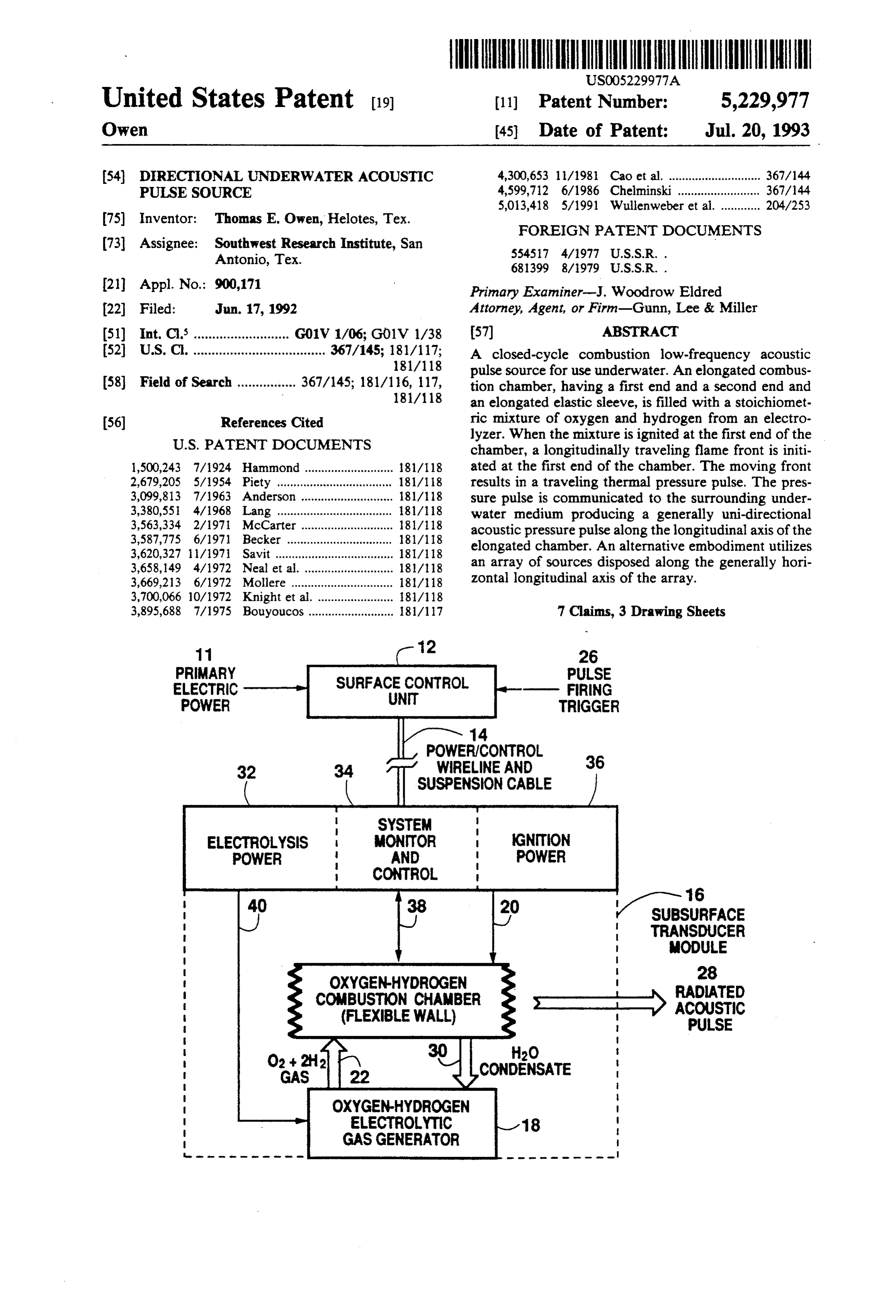
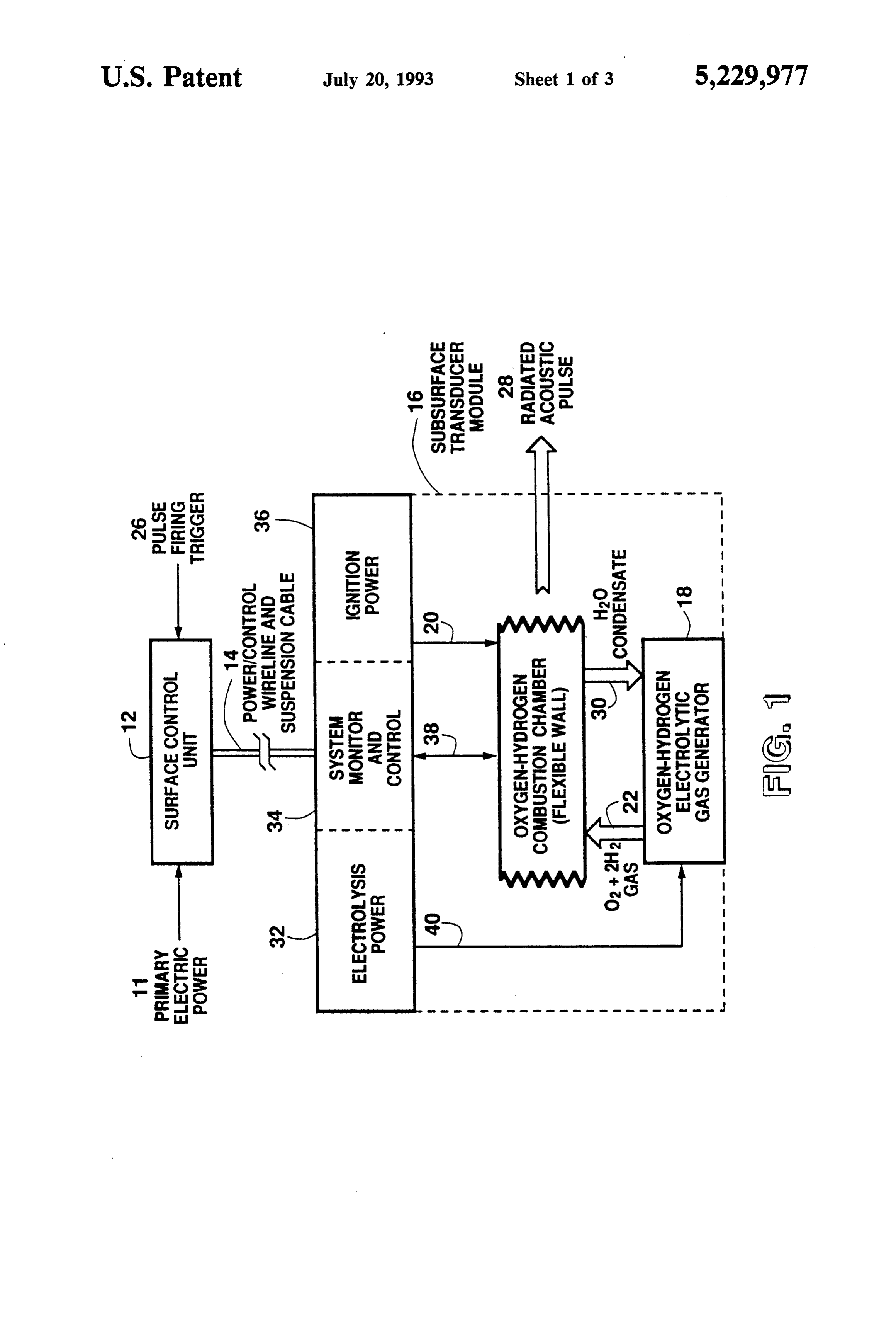
pled to the surrounding seawater medium to produce a DETAILED DESCRIPTION OF THE corresponding acoustic impulse. Through this electro PREFERRED EMBODIMENT lytic and thermodynamic process, latent chemical en ergy in the reactants as high as 100-200 kJoules may be In the present invention, the closed-cycle combus converted to sound wave energy in a chemically bal 5 tion-process thermo-acoustic pulse source operates by anced and cyclic manner. Thus, with only the input of first generating a stoichiometric mixture of oxygen and electrical energy to the electrolysis process, the oxygen hydrogen by electrolysis of water which is then ignited hydrogen combustion event occurs with negligible by to react by combustion. The combustion process gener products to produce a high-energy sound pulse and the ates a thermally driven transient over-pressure relative steam product of combustion condenses and is returned O to the local ocean hydrostatic pressure to produce, via to the electrolytic cell for reuse. a flexible combustion chamber interface, a radiated This process, employing reactants whose combustion sound pressure impulse. The gaseous reactants combine products need not be purged out of the combustion to the produce water vapor which, by heat exchange with surrounding environment, condenses to water liquid chamber after each cycle, is one of unusually high en 15 which is returned to the electrolytic cell to complete ergy density and, in analogy with other internal com the cycle. This cyclic process takes place in a self-con bustion processes, has the potential for precise timing tained subsurface transducer module designed to ac control. The electrical input energy governs the com commodate the various states of the operating cycle at bustion reaction energy and, correspondingly, the asso typical sonar system immersion pressures. This modular ciated acoustic energy. The size and physical design of O system is energized by electrical power transferred the combustion chamber governs the frequency spec from the surface by an armored wireline cable which trum of the radiated sound wave pulse. also serves as the transducer suspension cable. Ignition The intimate physical coupling and energy transfer of the combustion reaction impulses into the surrounding of the combustion pulse is provided by a high-voltage power supply and one or more spark plugs contained in water medium nakes this transducer technique excep 25 the transducer module. Ignition trigger pulses are trans tionally efficient; exceeded only by that of solid explo mitted to the transducer module from a surface control sive detonations for the desired low frequency sound unit. Source system performance monitoring data are signals of interest. Accurate combustion pulse tinning transmitted to the surface control unit by telemetry control allows several source modules of this type to be circuits contained in the wireline cable. operated with prescribed inter-element timing in a mul 30 FIG. 1 illustrates the closed-cycle repetitive acoustic tiple-element array to produce high energy acoustic pulse system in simplified block diagram form. In opera pulses having radiation directivity and a beam steering tion, primary electrical power 11 from the surface con capability. trol unit 12 and wireline cable 14 is conditioned in the The present invention seeks to provide acoustic subsurface transducer module 16 to operate the electro source transducers capable of generating high-power 35 lytic cell 18 and to supply a high-voltage ignition spark underwater sound pulses having predominant spectral 20 when triggered from the surface control unit 12. The content in the range of about 30-300 Hz and operating electrolytic cell or electrolyzer 18 generates an accu with good energy conversion efficiency and accurate rately stoichiometric mixture of oxygen and hydrogen timing control. The low-frequency pulse spectrum is gas 22 which flows into the flexible-wall combustion necessary in order to minimize the absorption. losses chamber 24 building up a chemical combustion charge along the longest practical sound propagation path whose energy content is dependent upon the effective while also achieving effective acoustic backscattering. current flow through the electrolytic cell. The gas mix Source energy conversion efficiency is important in ture in the combustion chamber will become pressur reducing the primary power demand necessary to drive ized as the electrolysis process proceeds, acting against the transducer and to minimize the size and weight of 45 the hydrostatic pressure external to the chamber. Nor the source system components. This factor combined mally, prior to operational use, the combustion chamber with the ability to accurately control the pulse initiation will be evacuated and the electrolyte degassed to re time, allows the source system to consist of an array of move any nonreacting gases which would otherwise high-power transducer elements which provide advan moderate the combustion temperature or produce po tages in spatial distribution of the source energy for 50 tentially contaminating by-products. better compatibility with the linear energy density limit When a firing trigger pulse 26 is transmitted to the of the water medium and provide useful beam forming subsurface module 16, the gas mixture in the combus directivity and beam steering. tion chamber 24 will be ignited and will burn rapidly to BRIEF DESCRIPTION OF THE DRAWINGS 55 produce high-temperature steam at a substantial pres sure rise proportional to the pre-combustion chamber
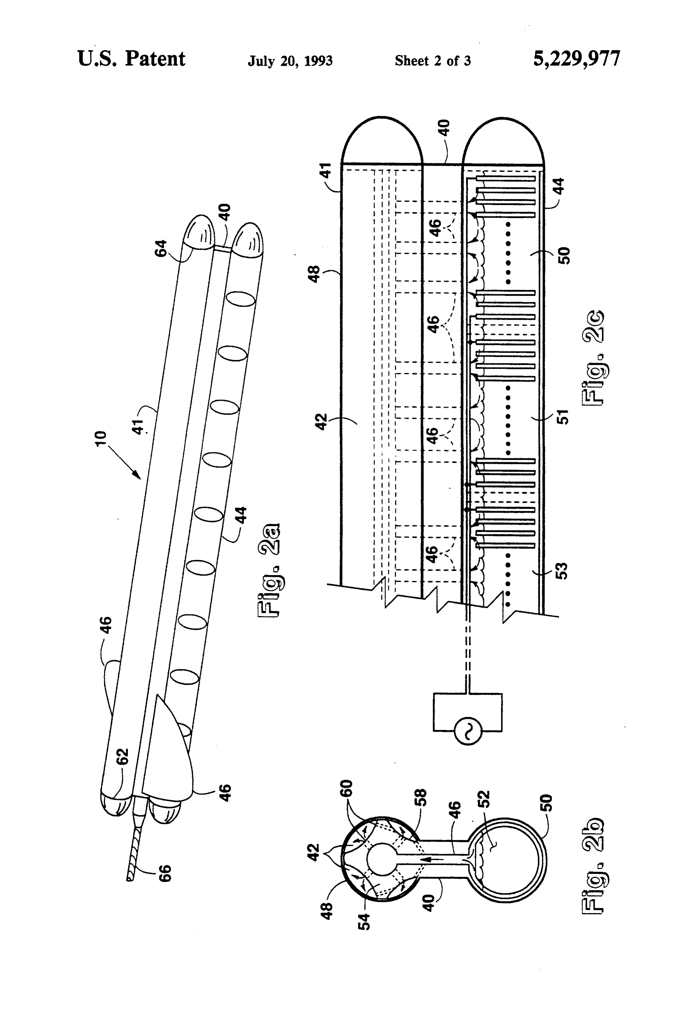
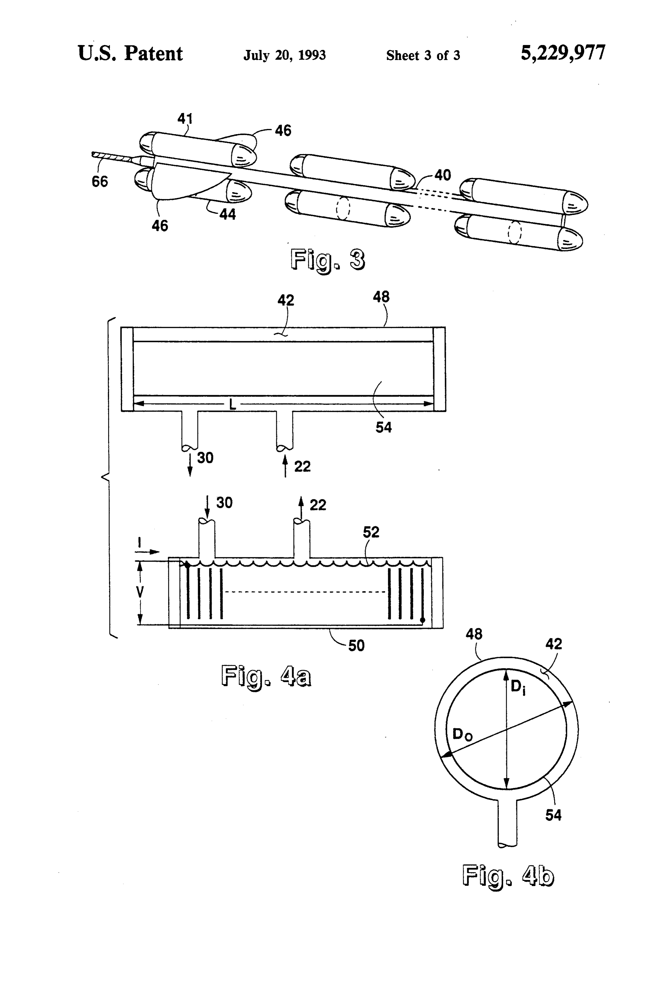
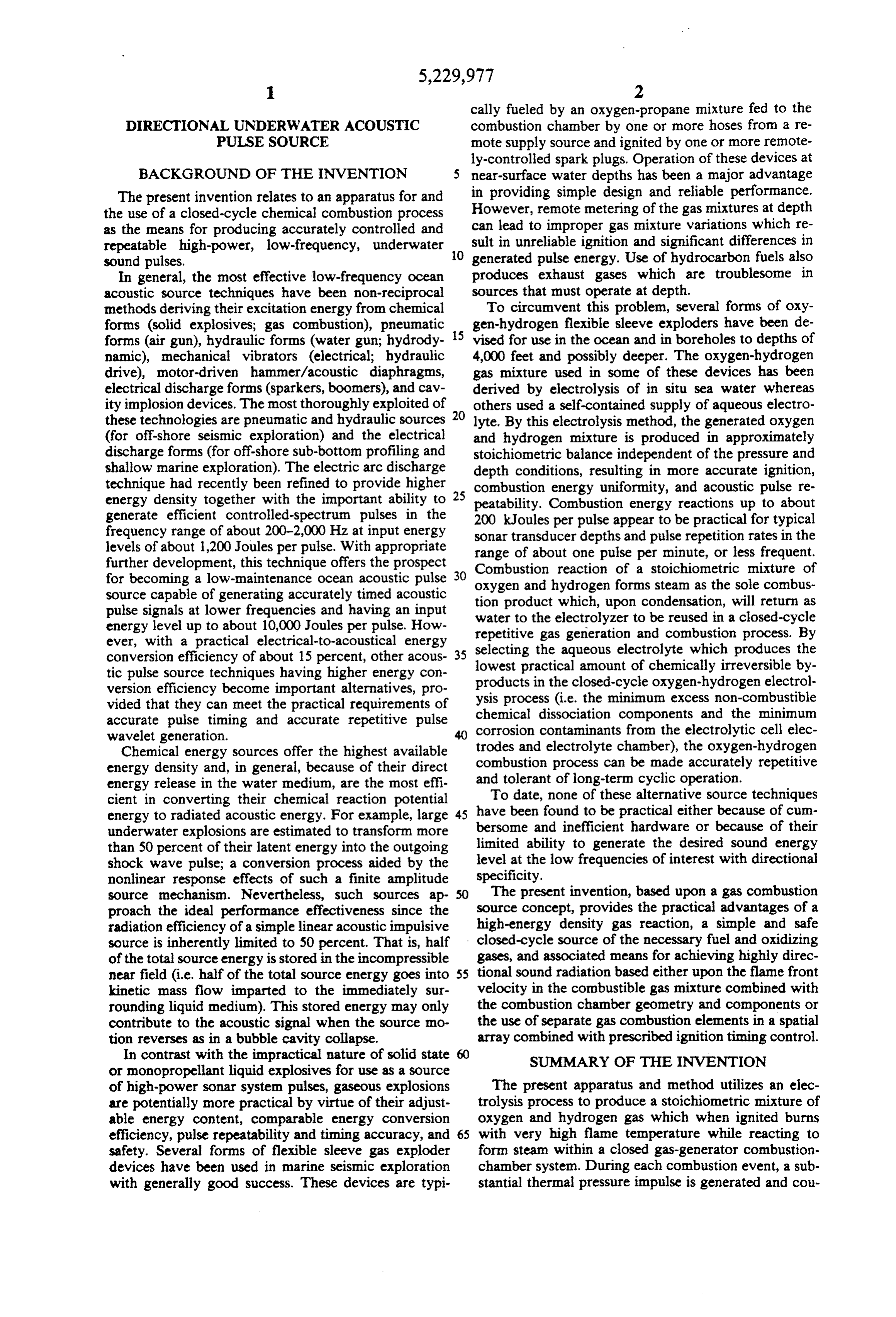
FIG. 1 illustrates the closed-cycle repetitive, acoustic pressure at the time of ignition. The incompressible pulse system in simplified block form. seawater medium surrounding the combustion chamber FIG. 2a illustrates a perspective view of the present 24 is directly subjected to the combustion pressure pulse invention. and will transmit an acoustic pressure impulse 28 whose FIG.2b illustrates an end cross-section of the present far field peak amplitude will depend upon the motional invention. velocity of the combustion chamber wall. Internal FIG. 2c illustrates a partial side cross section of the steam pressure, mechanical compliance of the chamber present invention. wall, heat storage and transfer from within the cham FIG. 3 illustrates an alternate embodiment of the ber, and kinetic energy in the surrounding medium present invention having an array of separate combus 65 interact to absorb the non-acoustic residual energy of tion chambers. the combustion process representing the energy deficit FIGS. 4A and 4B illustrate a simplified view of the which would otherwise allow the chemical-to-acoustic annular cylindrical combustion chamber configuration. energy conversion efficiency to be 100 percent. The
Page 7
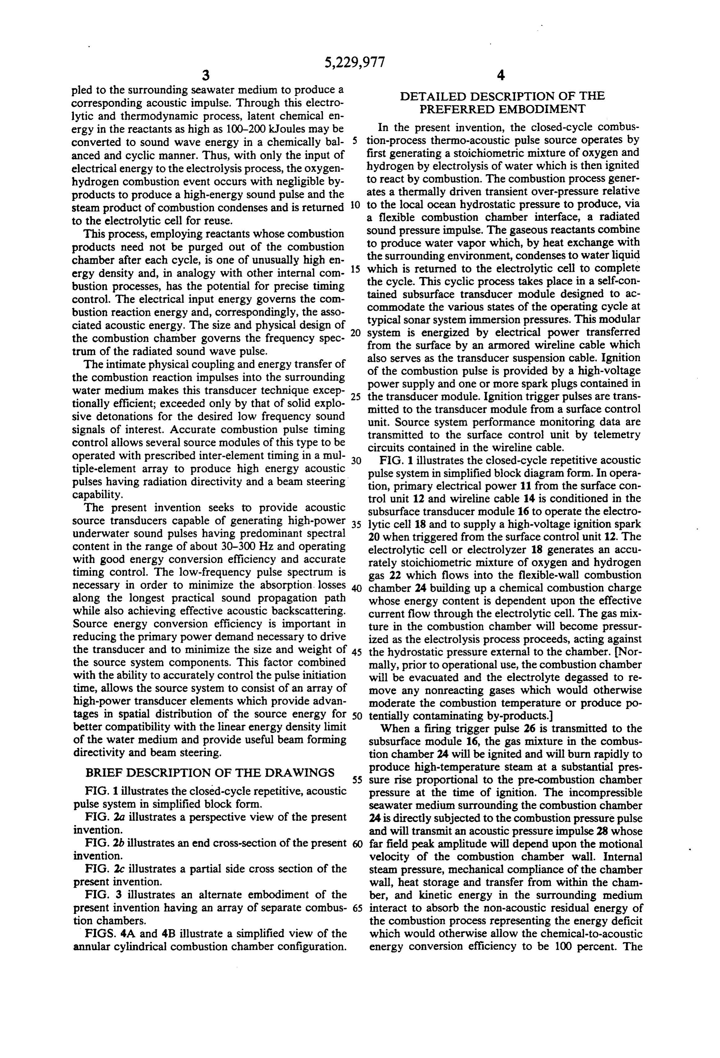
much slower collapse rate of the chamber, related pri energy input to the combustion process (i.e. to about marily to the condensation rate of the steam, will pro 200 kJ) is anticipated to shift the system operational duce a weaker and time delayed secondary acoustic limitations from the wireline power handling capacity pressure impulse, similar to the steam bubble collapse to the heat transfer design of the electrolytic cell and to pulse of an underwater explosion, which will radiate the strength of materials used in the flexible sleeve com into the far field as an indirect contribution to the acous bustion chamber. This limit is also estimated to be in tic efficiency of the source. Water 30 from the con excess of the linear acoustic energy density characteris densed steam is returned to the electrolytic cell where it tics of the water medium except at very deep depths. is reused in the next pulse cycle. The combustion process is one of very rapid burning The electrolysis process used to dissociate the aque O of the gas reactants in which typical flame front veloci ous electrolyte into oxygen and hydrogen is relatively ties are in the range of 1,000-2,000 m/sec. Thus, for inefficient because of electrical heating inherent in con well mixed gases, the combustion time duration will be ducting current through the bulk liquid (gas generation in the range of about 1 msec and will produce peak results only from the half-cell reactions at the elec temperatures in the range of about 2,500-3,000 K. trodes). Power losses in the electrolyte and the needed 15 When the combustion process occurs at constant vol gas production rate govern the size and heat transfer ume, then an estimate of the peak combustion overpres capacity of the electrolyzer. For a given geometric cell Sle is design, the gas production efficiency may be optimized by adjusting the conductivity of the electrolyte solu Ppkat(Tnar/Tamb)Pamb;
tion. Dilute aqueous solutions of strong acids (e.g. sulfu 20 ric acid) or bases (e.g. sodium hydroxide) are most com a value corresponding to about eight to ten times the monly used in oxygen-hydrogen electrolytic genera ambient immersion hydrostatic pressure of the trans tors. The chemical nature of these electrolytes will ducer. By coupling this pressure impulse to the sur govern the choice of the materials used to construct the rounding seawater through the flexible interface of a electrolytic cell. The preferred electrode materials are 25 high-temperature-rated elastomer sleeve, the chemical the noble metals although corrosion-resistant stainless reaction energy of the oxygen-hydrogen mixture is steel or certain conducting polymers well known in the efficiently transferred to acoustic and kinetic energy in art may serve as suitable alternative electrodes when the water medium. The combustion process induces used with certain electrolytes. high tensile stresses in the elastomer and exposes its An electrolytic cell or electrolyzer using a sodium 30 inner surface to high-temperature steam. Therefore, a hydroxide aqueous electrolyte will produce a stoichio tough high-temperature elastomer such as Kalrez (Du metric mixture of oxygen and hydrogen at an efficiency pont) or similar material is required and an expansion of about 25 percent when comparing the produced gas limiting outer cage may be used to restrict the physical constituent heating value energy with the electrical expansion of the sleeve. Ignition of the gas mixture may energy input. A simple one-stage cell will produce 35 be hindered by any residual water condensate in the 8.306X 10⁻⁵ g/sec of oxygen and 1.038X 10⁻⁵ g/sec of combustion chamber. Therefore, several independently hydrogen per ampere of current flow. The voltage drop fired spark plugs should be located within the combus across an ideal (100-percent efficient) electrolytic cell is tion chamber and heated to prevent fouling. 1.277 volt neglecting any power losses in the bulk liquid The physical size and combustion energy of the trans electrolyte. For electrolyte concentrations which yield ducer are factors that establish the practical physical only the desired stoichiometric gas mixture (no other scale and material stress limits. Combustion chamber adverse electrode reactions) a typical cell voltage will volumes ranging from about 15 in to 60-80 in cover be approximately 2.0 volts, taking into account the bulk the practical range for the low-frequency high-power liquid voltage drop. Considering the remote operating acoustic impulses of interest in the present invention, requirement of the transducer, with the wireline cable 45 i.e., 30-300 Hz.
as a significant part of the electrolytic power delivery FIGS. 2a, 2b, 2c and 3 illustrate towed arrays of the circuit, a series cascade of such cells offers a practical present invention 10 described above. In FIG. 2(a), the design approach. Thus, given a wireline cable having a rectangular strut 40 along the central length of these specific voltage rating and conductor resistance, there arrays is the rigid strength member of the assembly will be an optimum number of electrolytic cells for whereas the upper 41 and lower 44 cylindrical sections maximally efficient gas production. Further, although form the flexible combustion chambers and the rigid not necessarily a constraint in low repetition rate acous electrolysis cells, respectively. Stabilizing fins 46 near tic pulse source systems, the maximum gas production the forward end maintain the array vertically oriented energy rate will generally be limited by the wireline with the combustion sleeve 48 at the top and the elec cable. As a preliminary design configuration, the elec 55 trolysis cells 50 at the bottom. trolytic cell may consist of 50-100 cascaded stages oper FIG. 2(b) illustrates an end cross-section of the de ating at a series current of about 8-10 amperes supplied vice, showing the electrolytic cell 50 containing an by a surface sending end voltage of 2-300 volts on the aqueous electrolyte 52 at the bottom and the flexible wireline cable. In such a case, a 100-stage cell will gen sleeve 48 and an internal core body 54 at the top. erate about 10 liters of hydrogen at standard tempera The internal core body may be a rigid member ex ture and pressure per minute; a useful production rate tending the length of the chamber. The core size may that may be increased, if necessary, by a factor of 2-4 to vary to determine the volume of oxygen and hydrogen meet higher energy or rapid pulse repetition rate opera which may be received in the chamber. The rectangular tion. The associated latent chemical energy content of a strut 40 provides passageways 46 for oxygen and hydro stoichiometric mixture of 10 liters of hydrogen and 5 65 gen gas to enter or communicate with the combustion liters of oxygen is 67,760 Joules and, in complete closed chamber 42 and to tend to inflate the sleeve 48 in the cycle operation, is determined from the lower heating concave rib zones 58 around the internal core 54. Nu value of hydrogen. An increase of about three times this merous gas passage holes 60 perforate the core to per
Page 8
mit free movement of the gas mixture before combus part of the combustion pressure pulse energy efficiently tion and to permit drainage of the condensed water after transformed into a radiated sound wave. The combus combustion. tion pressure pulse, traveling at the speed of sound in FIG. 2(c) shows a side cross-section illustrating two sea water along the length of the flexible sleeve, acts in of the adjacent electrolysis cells 50 and 51 and their a constructive way to inherently reinforce the water parallel electrical connections. The cascade of multi borne sound wave traveling in the direction of the com electrodes in each electrolysis cell consists of 50-100 bustion pulse. This process discriminates against sound electrode plates designed to operate at 100-200 volts waves radiated in the direction opposite to that of the applied at each end; the ends being electrically con traveling combustion pulse, resulting in a one nected at common voltage polarities to force proper O current flow through each cell. The evolved oxygen dimensional fire” sound line radiator having a preferential "end radiation pattern along the longitudinal and hydrogen are mingled directly upon liberation and rise upward through narrow passageways 46 in the sleeve axis in the direction of the traveling combustion strength member strut 40 to enter the combustion cham pulse.
ber 42. In the continuous combustion chamber shown, 5 (5) The flexible-sleeve combustion transducer may the combustion process is initiated at the forward end 62 consist, in an alternate embodiment as shown in FIG. 3, of the chamber and the resulting combustion pulse trav of an array of separate combustion compartments or els at the flane-front velocity to the aft end 64 of the modules, fed either from a common electrolytic gas chamber. The sound wave impulse generated in the generator or from individual electrolytic gas genera surrounding seawater is directed aft of the towed array. tors, and having independent ignition circuits and igni The shape and perforated characteristics of the internal tion timing control. By placing these modular elements core 54 within the flexible sleeve 48 is designed to influ in a prescribed spatial array relationship, and control ence and adjust the oxygen-hydrogen flame-front ve ling their pulse ignition times in prescribed relation locity to be approximately equal to the velocity of ships, the array can produce desirable sound radiation sound in sea water at the typical depth intended for the 25 patterns which may be adjusted in beamwidth and di source transducer operation. Operating power and igni rection. For example, when such a modular array con tion control signals are supplied from the surface vessel taining a number of closely spaced elements is arranged via the towing cable 66. in a straight line and the modules triggered at delayed The directional underwater acoustic pulse source 10 ignition times beginning at a first end and ending at an
(1) High impulsive sound energy created by the com opposite end, then a discrete-element array similar to bustion reaction of stoichiometrically mixed oxygen the continuous-sleeve concept described is obtained. and hydrogen. Efficient end-fire sound radiation is obtained from this (2) Closed-cycle combustion operation involving discrete-element array when the ignition delay times cycle steps wherein water is first decomposed by elec 35 between adjacent elements are the same as the sound trolysis to produce oxygen and hydrogen in stoichio pulse travel time in the surrounding sea water as gov metric proportions, the oxygen and hydrogen mixture is erned by the spacing distances between the adjacent next ignited to cause a rapid impulsive chemical reac elements and the speed of sound in the sea water. tion and associated thermal expansion process in which FIGS. 4a and 4b illustrate a simplified physical layout the only combustion by-product is steam, and finally the of the annular cylindrical combustion chamber configu steam cools and condenses to water which is returned to ration. The rigid center body 54 of the combustion the electrolysis process for reuse. chamber 42 is employed to increase the surface area of (3) The combustion chamber in which the oxygen the active surface of the source and to provide control and hydrogen gases react is a flexible sleeve through which the impulsive pressure associated with the heat 45 of the volume displacement of the source independent of combustion imparts a pressure into the surrounding eters ofcombustion of the chamber volume. The design param medium (sea water) to produce an impulsive shock follows: the pulse source of FIGS. 4a and 4b are as wave or sound wave having an acoustic energy level which is a substantial fraction of the chemical energy of the reactant gases. SO Preliminary Design of a Oxygen-Hydrogen (4) The flexible-sleeve combustion chamber consists, Combustion Pulse Source in a first form, of a tubular elastomer channel in which Number of electrolysis Cells: 75 combustion of the contained reactant gases is initiated at Length of Combustion Chamber
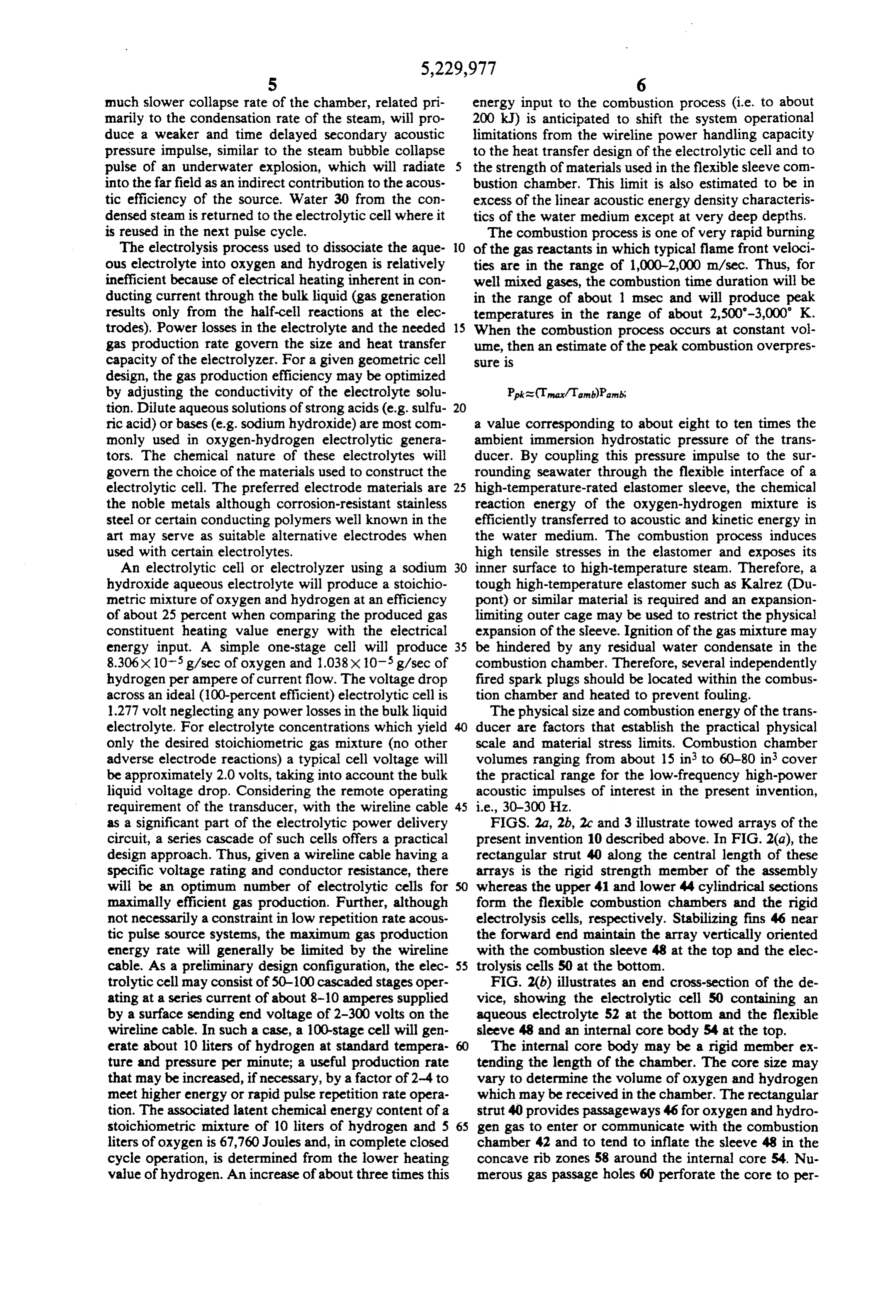
a first end, the resulting combustion process travels Annular Volume of Combustion 3.141 = 3.14 x 10m along the sleeve toward the second end at a flame-front 55 Chamber: D = 0.254 m velocity which is dependent upon the combustion gas Applied Voltage (75 cells) Di is 0.246 m. 97.5 V (rms) (neglecting constituents, their ambient conditions, and the sleeve electrolyte voltage drop) geometry, whereafter the combustion cycle ends when Current in 75-Cell Cascade: 10 A (rms) the flame front reaches the second end of the flexible Operating Power: 975 W. sleeve. Thermal expansion of the reacting gases forms a Charging time to store 236 kJ 240 sec (4 min) traveling pressure front in the flexible sleeve, pressuriz latent energy:
ing and expanding the sleeve outwardly against the Peak Combustion impulse 9.786 x 10⁶ Pa (1,419 psig) surrounding seawater medium and, thereby, progres Pressure: (At depth of 100 m in seawater
sively generating generally uni-directional acoustic sound waves in the water along the length of the sleeve. 65
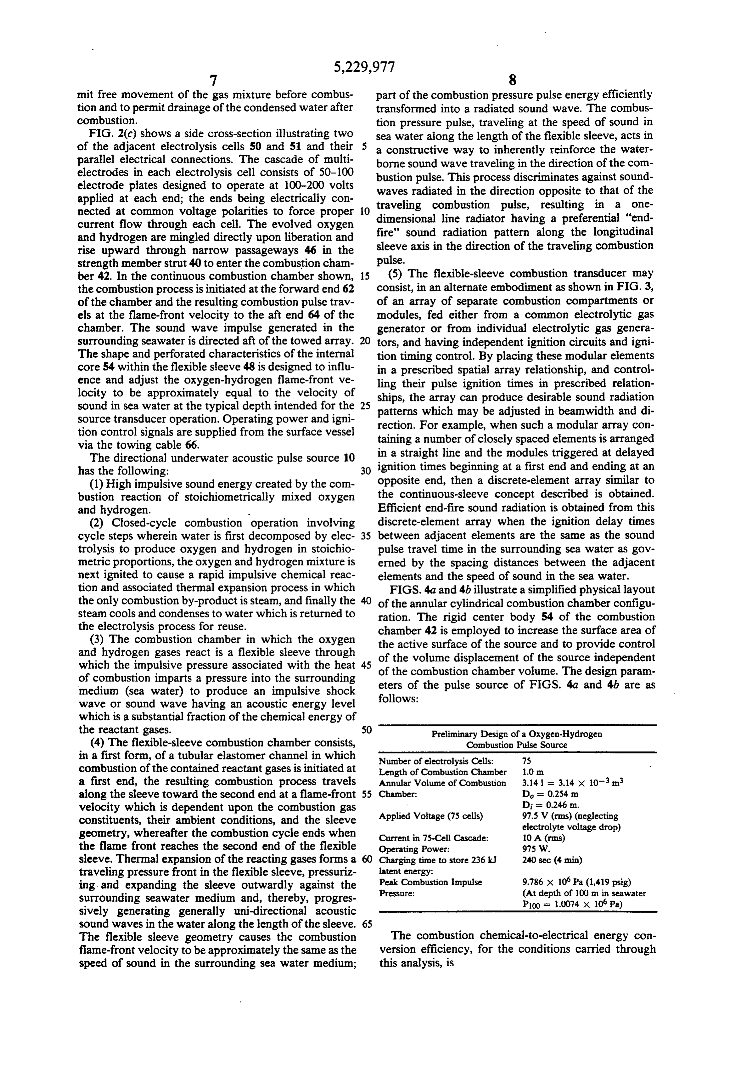
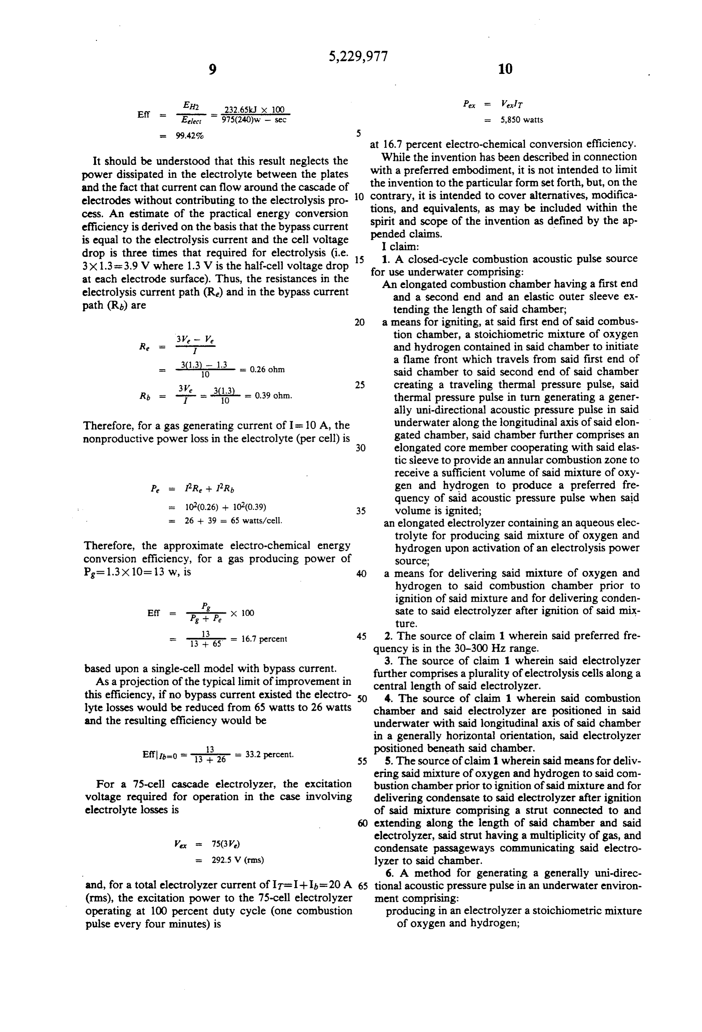
The flexible sleeve geometry causes the combustion The combustion chemical-to-electrical energy con flame-front velocity to be approximately the same as the version efficiency, for the conditions carried through speed of sound in the surrounding sea water medium; this analysis, is
Page 9
Pex Ver
Eff s.T - Elect
975(240)w - sec = 5,850 watts
at 16.7 percent electro-chemical conversion efficiency.
It should be understood that this result neglects the While the invention has been described in connection power dissipated in the electrolyte between the plates with a preferred embodiment, it is not intended to limit and the fact that current can flow around the cascade of the invention to the particular form set forth, but, on the electrodes without contributing to the electrolysis pro O contrary, tions, and it is intended to cover alternatives, modifica equivalents, as may be included within the cess. An estimate of the practical energy conversion spirit and scope of the invention as defined by the ap efficiency is derived on the basis that the bypass current pended claims.
is equal to the electrolysis current and the cell voltage I claim:
drop is three times that required for electrolysis (i.e. 15 1. A closed-cycle combustion acoustic pulse source 3x1.3=3.9 V where 1.3 V is the half-cell voltage drop at each electrode surface). Thus, the resistances in the forAn use underwater comprising: elongated combustion chamber having a first end electrolysis current path (R) and in the bypass current and a second end and an elastic outer sleeve ex path (R) are tending the length of said chamber; 20 a means for igniting, at said first end of said combus 3W - We tion chamber, a stoichiometric mixture of oxygen Re - and hydrogen contained in said chamber to initiate a flame front which travels from said first end of 31.3 - = 0.26 ohm said chamber to said second end of said chamber creating a traveling thermal pressure pulse, said
thermal pressure pulse in turn generating a gener ally uni-directional acoustic pressure pulse in said
Therefore, for a gas generating current of I= 10A, the underwater along the longitudinal axis of said elon nonproductive power loss in the electrolyte (per cell) is 30 gated chamber, said chamber further comprises an elongated core member cooperating with said elas tic sleeve to provide an annular combustion zone to receive a sufficient volume of said mixture of oxy
P = PR -- PR, gen and hydrogen to produce a preferred fre
quency of said acoustic pressure pulse when said 35 volume is ignited;
= 26 -- 39 = 65 watts/cell. an elongated electrolyzer containing an aqueous elec trolyte for producing said mixture of oxygen and
Therefore, the approximate electro-chemical energy hydrogen upon activation of an electrolysis power conversion efficiency, for a gas producing power of Source;
Pg=1.3x10=13 w, is 40 a means for delivering said mixture of oxygen and hydrogen to said combustion chamber prior to ignition of said mixture and for delivering conden
Ef -- x 100 sate to said electrolyzer after ignition of said mix
13 45 2. The source of claim 1 wherein said preferred fre
quency is in the 30-300 Hz range.
based upon a single-cell model with bypass current. 3. The source of claim 1 wherein said electrolyzer further comprises a plurality of electrolysis cells along a
As a projection of the typical limit of improvement in central length of said electrolyzer. this efficiency, if no bypass current existed the electro- so 4. The source of claim 1 wherein said combustion lyte losses would be reduced from 65 watts to 26 watts chamber and said electrolyzer are positioned in said and the resulting efficiency would be underwater with said longitudinal axis of said chamber in a generally horizontal orientation, said electrolyzer 3 positioned beneath said chamber.
5. The source of claim 1 wherein said means for deliv ering said mixture of oxygen and hydrogen to said com
For a 75-cell cascade electrolyzer, the excitation bustion chamber prior to ignition of said mixture and for voltage required for operation in the case involving delivering condensate to said electrolyzer after ignition electrolyte losses is of said mixture comprising a strut connected to and 60 extending along the length of said chamber and said electrolyzer, said strut having a multiplicity of gas, and ex 75(3V) condensate passageways communicating said electro
6. A method for generating a generally uni-direc and, for a total electrolyzer current of IT=I-I-Ib=20 A 65 tional acoustic pressure pulse in an underwater environ (rms), the excitation power to the 75-cell electrolyzer ment comprising:
operating at 100 percent duty cycle (one combustion producing in an electrolyzer a stoichiometric mixture pulse every four minutes) is of oxygen and hydrogen;
Page 10
delivering said mixture to an elongated combustion frequency of said acoustic pressure pulse is deter chamber having a first end and a second end and an mined by varying the volume of said delivered elastic outer sleeve extending the length of said mixture in said chamber by varying the volume of chamber; a core element positioned within said chamber, said igniting said mixture at said first end of said chamber 5 acoustic pulse traveling in the direction of said to initiate a flane front which travels from said first length of said chamber;
end of said chamber to said second end of said collecting condensated steam after said igniting for chamber creating a traveling thermal pressure delivery to said electrolyzer. pulse, said thermal pressure pulse in turn generat- 7. The method of claim 6 wherein said frequency is in ing said generally uni-directional acoustic pressure 10 the range of 30-300 Hz.
pulse in said underwater environment wherein the . . . . .
Provenance
- Collection
- Cited prior art
- Original PDF
- patentimages.storage.googleapis.com →
- Filed
- 1992-06-17
- Pages
- 10
- Method
- pdftotext (the PDF's own text layer) + pdftoppm 300dpi page scans
- Source
- Google Patents bibliographic record
- Granted
- 1993-07-20
- Inventors
- Thomas E. Owen; Southwest Research Institute SwRI
- Transcribed from
- patentimages.storage.googleapis.com →