patent · US4323113
Underground air tempering system
6 April 1982
Page 1 — bibliographic record
United States Patent (19) (11) 4,323,113 Troyer 45 Apr. 6, 1982 (54) UNDERGROUND AIR TEMPERING FOREIGN PATENT DOCUMENTS
SYSTEM
475226 2/1915 France .................................. 165/45 76 Inventor: LeRoy S. Troyer, 3019 Essex, South 1089865 3/1955 France ....... ... 165/45 Bend, Ind. 46615 248161 1/1948 Switzerland .......................... 165/45 Primary Examiner-Sheldon J. Richter 21 Appl. No.: 202,587 Attorney, Agent, or Firm-Marmaduke A. Hobbs
(22 Filed: Oct. 31, 1980 An underground air tempering system for warming the supply air to a building in the winter and cooling the 51) Int. Cl. ................................................. F24J 3/02 supply air in the summer in which a heat exchanger 52 U.S. Cl. ...................................................... 165/45 containing heat transfer material is disposed beneath the 58) Field of Search ........................... 165/45, DIG. 4; surface of the ground and the air supply to the building 126/400 is drawn through the heat exchanger to be tempered by the substantially constant ground temperature. Two or 56) References Cited more heat exchangers may be interconnected on the air
cient volume of tempered air to large buildings. The 706,451 8/1902 Rector ................................... 165/45 underground air tempering system cleanses the air by 1,974,244 9/1934 Lapp ..................................... 165/45 removing dust and other particles therefrom, and mod 2,119,038 5/1938 Bell ....................................... 165/45 erates the humidity of the airby warming and humidify 2,217,190 10/1940 Urquhart. 165/45 ing cold dry winter air and by cooling and dehumidify 2,427,780 9/1947 Haines ..... . . 165/45 ing hot moist summer air. To maintain free flowing air 2,793,509 5/1957 Keen ....... - - - -- - - --- - - - - - - --- - -
3,424,232 1/1969 Garrett .................................. 165/45
passages, and to eliminate fungal and bacterial growth 4,024,910 5/1977 Werner ................................. 165/45 in the heat exchanger, a disinfectant and wash solution 4,051,891 10/1977 Harrison . . 126/400 system is disposed above the heat transfer material for 4,106,555 8/1978 Quintal .................................. 165/45 periodic cleansing of the material. 4,205,656 6/1980 Scarlata ... ... 126/400 4,234,037 11/1980 Rogers et al. ......................... 165/45 24 Claims, 6 Drawing Figures
s Aasarayas
Page 2
Drawing sheet — no readable text.
Page 3
Drawing sheet — no readable text.
Page 4
Drawing sheet — no readable text.
Page 5
Drawing sheet — no readable text.
Page 6
sumner temperatures approach 100 F. and winter tem
UNDERGROUND AIR TEMPERING SYSTEM peratures plunge to below 0. F., significant energy sav ings can be obtained by tempering the makeup air to be
BACKGROUND OF THE INVENTION used in heating and cooling systems for buildings at A substantial portion of the total amount of energy 5 minimal energy expense. It is therefore one of the prin consumed annually is used for heating and cooling of cipal objects of the present invention to provide an buildings, including homes, factories, office buildings underground air tempering system which utilizes the and the like. As a result of the tremendous increases in natural temperature buffer present below the earth's energy costs, it has become cost effective on a long term surface to warm the makeup air for building heating basis to invest larger sums of money in energy conserva- 10 systems during cool weather at an energy expenditure tion than it was in the past when energy was relatively substantially below the cost for conventionally heating inexpensive. Architects and engineers have become the air to similar temperatures, and which will cool the aware of this fact, and previously unused or little used makeup air for building cooling systems during warm technology for the more efficient use of natural energy weather at substantial energy savings over conventional resources, such as active or passive solar heating and air cooling methods.
the increased use of old technology such as building These and other objects are accomplished in the pres insulation, can be economically incorporated in virtu ent invention by providing an underground housing or ally any building when the long range cost savings series of housings disposed at a depth where constant therefrom are considered. Solar collectors to harness ground temperatures are present, or where temperature the energy from the sun have been developed and al- 20 variations are present only in a fly wheel effect. The tered, made complicated and simplified, with predict housings are filled with rocks or other material to serve ably mixed results, particularly in severe climates and in as areas which experience extended periods of cloudiness in heat the exchangers, and the air to be used as makeup air building is drawn through the heat exchangers.
or overcast skies. One of the principal difficulties with The air drawn therethrough may comprise 100% fresh the use of previous solar energy systems for heating 25 makeup air, 100% return or exhaust buildings is that, in addition to the large initial installa ing, or any variation of a combinationairoffrom fresh the build makeup tion cost, the systems generally require direct, intense air and return air. The air is warmed during cold sunlight. The rays from the sun are most indirect, and months and cooled during hot months to substantially thus most inefficient, during the coldest months of the reduce the burden on conventional heating and cooling year when heating is required in a building, and the rays 30 are most direct, and hence most heat creative for a solar equipment.
ing
A fan or blower is the only energy consum component in the present system and will normally heating system, during the summer months when typi cally the requirement is for cooling a building. Previous be of similar size to the air handler required by conven solar systems do not work well during cloudy or over tional heating or cooling systems in similar buildings. cast days, and without storage systems, may cease oper- 35 Thus the cost for moving the air in the present invention ating entirely if prolonged absences of direct sunlight is the same as in previous heating or cooling systems; OCC. however, the present system consumes no energy in The largest and most reliable solar energy collector performing the actual temperature modifications as do available to mankind is the earth itself. It has long been the previous systems. The housing containing the rocks known that subsurface ground temperatures below the 40 is normally waterproofed, and a sprayer system to clean frost line are relatively stable. At a depth of 10 to 12 feet and disinfect the rocks or other material to prevent below the ground surface in most temperate zone loca fungal and bacterial growth is disposed at the top of the tions, a relatively constant ground temperature of 55° is material with a sump pump and drainage system dis present. Heating and cooling of the ground at more posed therebelow.
shallow depths do occur; however, the rate at which 45 Another object of the present invention is to provide temperatures at the surface of the ground penetrate into an underground air tempering system which can be the ground in slow. Hence, the highest subsurface soil installed in a cost efficient manner so that the installa temperatures are reached during the late fall and early tion cost thereof can be returned in energy savings over winter months when above ground temperatures ap a short period of time, and which can be used as a sup proach the coldest, and the coolest subsurface tempera- 50 plement to most conventional heating or cooling sys tures are present during the late spring and early sum temS.
mer months when the above surface temperatures are A further object of the present invention is to provide approaching the warmest. This phenomenon, whereby an underground air tempering system which will pro the subsurface temperature cycle is out of phase with vide humidity control to some degree, to reduce the the above ground temperature cycle, is referred to as a 55 humidity content of the building makeup air during the "thermal fly wheel' effect, and manifests itself to a summer cooling months, and to increase the humidity small degree in temperature fluctuations between day content thereof during winter heating months, and time and night time as well as between warm months which will perform the additional function of filtering and cold months. Hence, the earth as a solar collector and cleansing the makeup air to provide substantially functions opposite to conventional above ground solar 60 clean air for the climate control system of a building. collectors which rely on direct sunlight for operation, Yet another object of the present invention is to pro in that the earth reaches its warmest temperatures when vide an underground air tempering system which has heating would be required in buildings and the earth is only a few moving parts and requires only minimal at its coolest temperature when cooling is required. maintenance for the upkeep thereof, and which has little 65 or no environmental impact during either installation or
Especially in areas which experience large average Still another object of the present invention is to temperature variations from month to month, wherein provide an underground air tempering system which
Page 7
can be used with other energy saving construction tech and larger embodiments will be more fully described niques, such as for example, envelope building construc hereinafter.
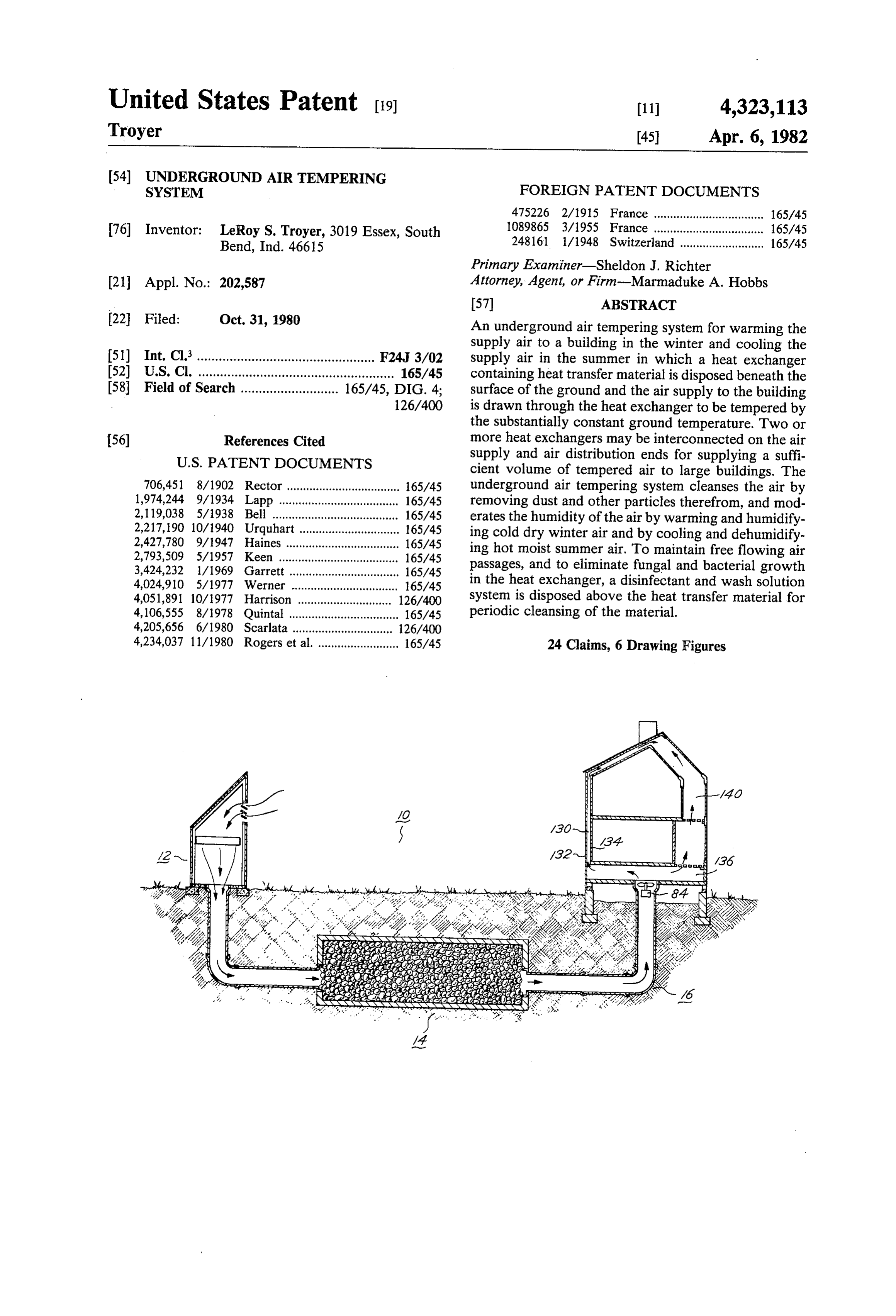
tion, and which will not interfere with the aesthetic Air mixing and supply section 12 includes an air in design of buildings or surrounding grounds of buildings. take structure which, in the embodiment shown, is a Additional objects and advantages of the present small building or shed 20 through which fresh outside invention will become apparent from the following makeup air enters the system. Building 20 is an enclosed detailed description and the accompanying drawings. structure having a roof 22 and walls 24, with an air inlet opening 26 in one of the walls, which normally will
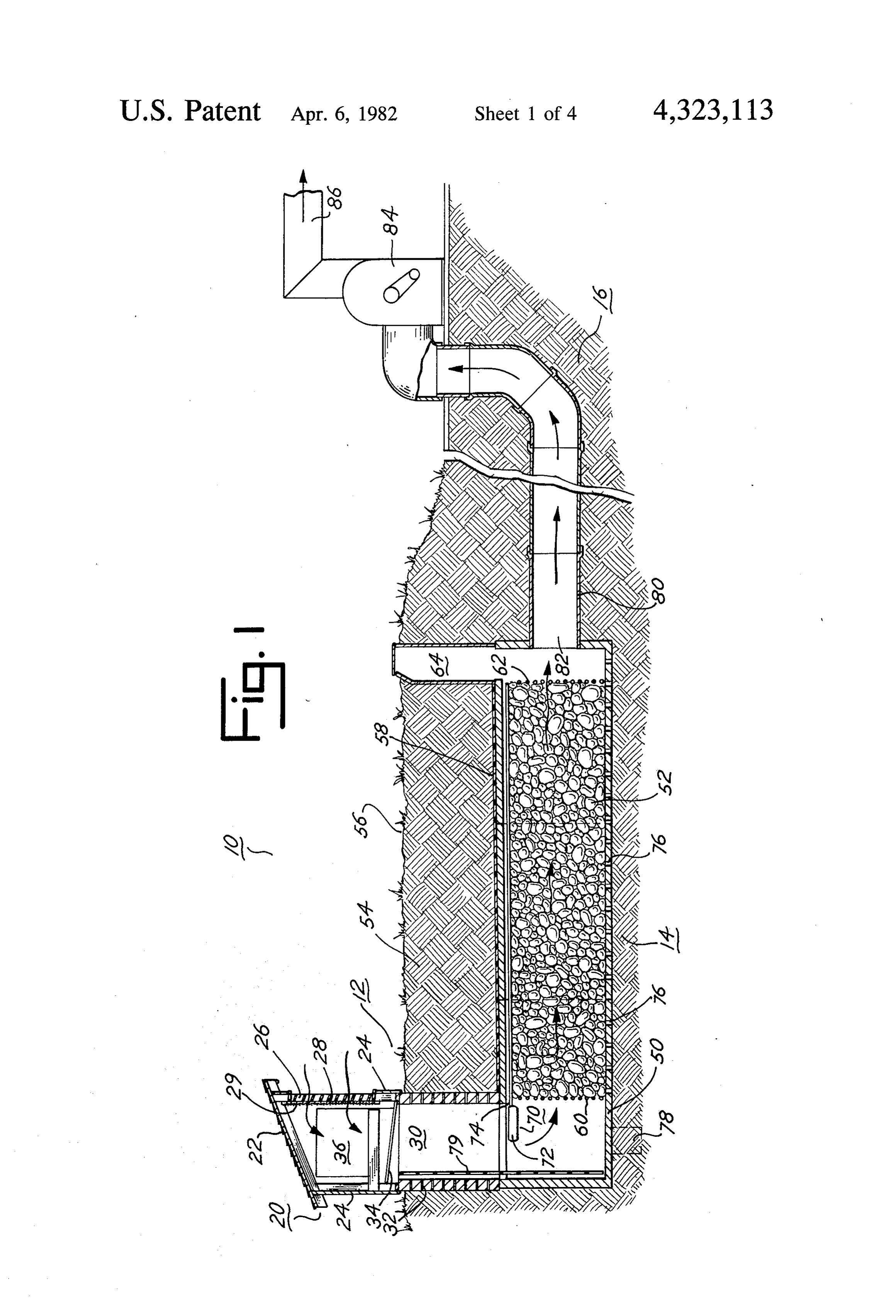
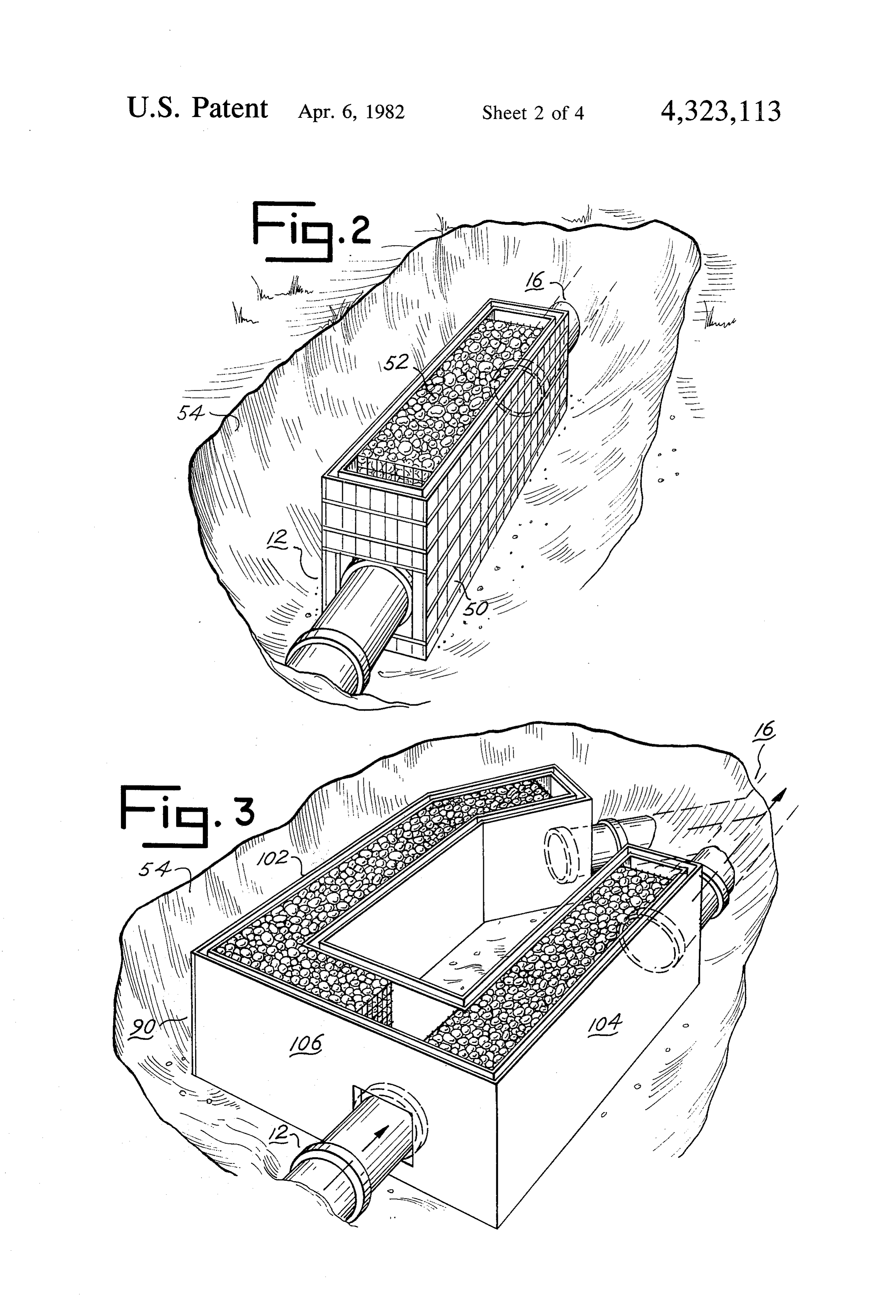
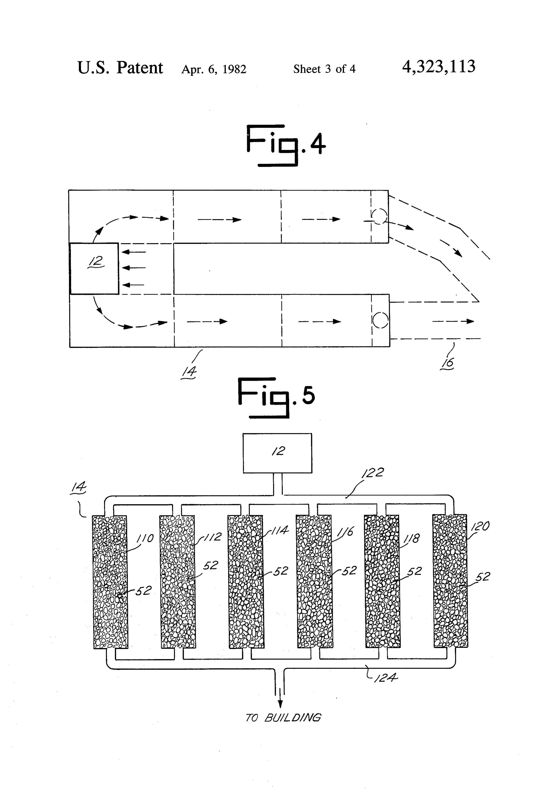
BRIEF DESCRIPTION OF THE DRAWINGS have louvers 28 to prevent rain and large debris such as FIG. 1 is a vertical cross sectional view of the present 10 leaves and sticks from entering building 20. A screen 29 underground air tempering system; disposed behind louvers 28 prevents smaller contami FIG. 2 is a perspective view of an embodiment of the nants from entering the building. The building is dis present invention suitable for use with a small building posed over an air shaft 30 which extends from the having relatively small volume makeup air require ground surface downwardly to heat exchanger 14. ments; 15 Walls 32 of shaft 30 may be of any suitable material; FIG. 3 is a perspective view of a larger embodiment however, poured concrete sections and/or concrete of the present invention then that shown in FIG. 1, for blocks have been found suitable while providing easy use in a larger building having larger volume makeup installation. Building 20 has no base or bottom floor, but air requirements; opens directly into shaft 30 so that air entering the FIG. 4 is a top plan view of a medium size under building will pass therethrough and down shaft 30 to ground air tempering system, indicating the air flow heat exchanger 14. Filters and/or screens 34 are dis patterns therethrough; posed over the opening to shaft 30 to further cleanse the FIG. 5 is a diagrammatical view of an underground air entering the tempering system. In some applications, air tempering system which may be modified as re 25 mayreturn the air from the building climate control system quired for large buildings having large volume makeup 12 bybeappropriatebrought into the air mixing and supply section ducts, and an air mixing box 36 of air requirements; and
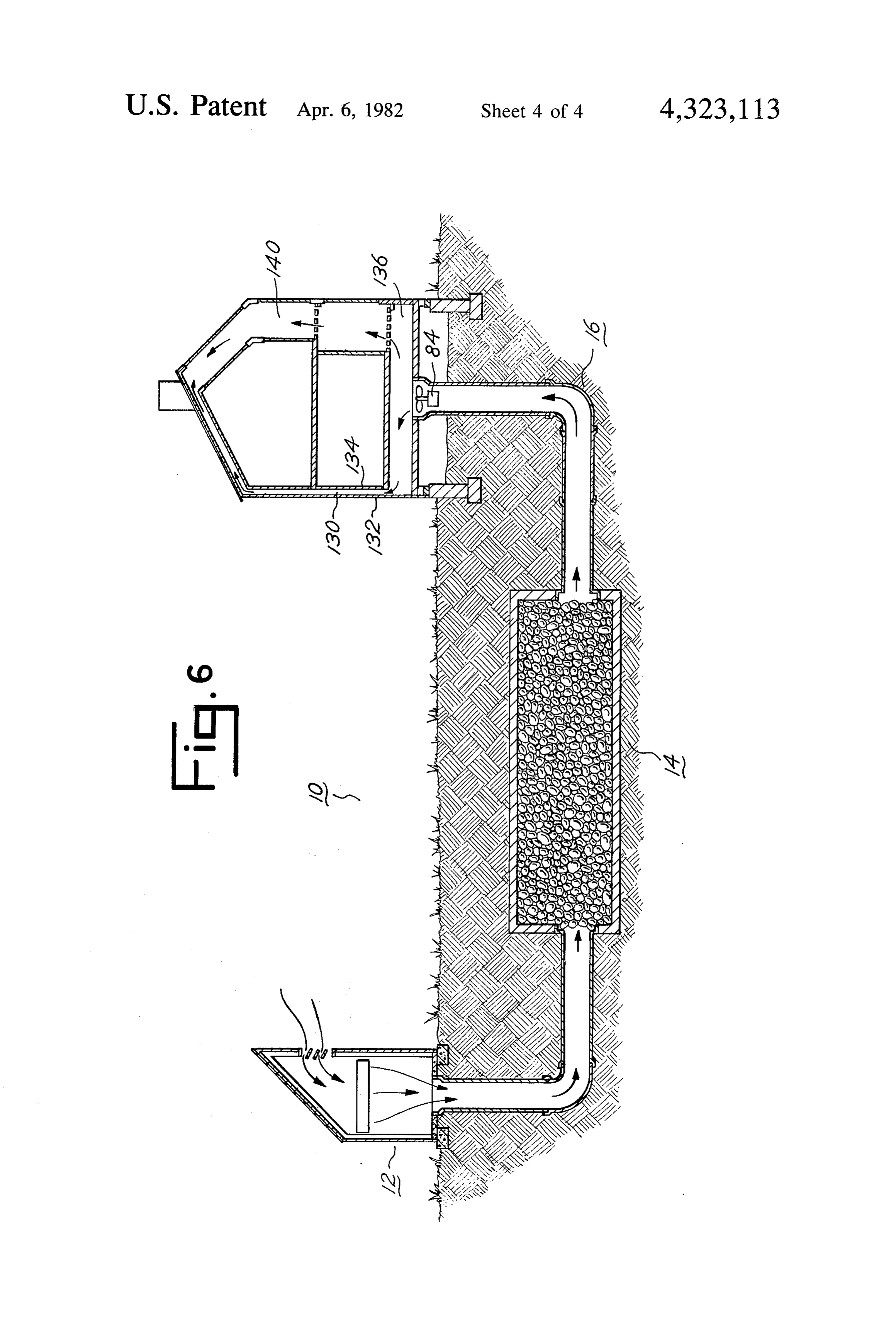
FIG. 6 is a vertical cross sectional view showing one fresh makeup air andmay conventional design be used to vary the mixture of particularly advantageous use of the present under pass into shaft 30. It shouldairbewhich return is permitted to understood that, al ground air tempering system, 30 though in some applications the air intake structure will DETAILED DESCRIPTION OF THE be a separate building as shown in the drawings, in PREFERRED EMBODIMENT many instances the intake structure will consist of a vent Referring now more specifically to the drawings, and theand ducts in the building being supplied with air from present tempering system, and the air mixing box 36, to FIG. 1 in particular, numeral 10 designates an under 35 filters 34 and the like will be disposed in mechanical ground air tempering system embodying the present equipment spaces within the building, with ducts and an invention which may be used with virtually any build air shaft or shafts to the heat exchanger. ing, from single family residential dwellings to public Heat exchanger 14 is comprised generally of a hous buildings, including restaurants, churches and the like, ing 50 filled with a heat transfer material 52. Housing 50 as well as factories, office buildings, farm buildings, is disposed in the ground 54 at a depth at which the such as poultry and hog sheds or cattle barns, or any temperature is relatively constant or at which the usable building which requires some degree of interior climate thermal fly wheel effect is present. Normally the dis control. The present system is useful during cold tance from the ground surface indicated by numeral 56 weather when heating is required and can substantially to the top of housing 50 will be approximately five (5) to reduce the energy cost for heating a building, and the 45 six (6) feet; however, this distance may vary, depending present system is also useful during warm weather on the location of the system and the desired perfor when cooling is required for interior building spaces. In mance of the system. The distance between surface 56 some applications the present system can entirely re and the bottom of housing 50 will be twelve (12) feet in place conventional centralized air conditioning systems, a typical installation for a medium size system; how and will totally preclude the need for compressors and 50 ever, again this distance may vary depending on many outdoor fan units used with conventional centralized air factors, including the volume of air required from the conditioning. The present system may also be used as a system which will affect the desired cross sectional area supplement to centralized air conditioning, and will of housing 50. Concrete has been found to be a suitable substantially reduce the energy expenditures in cooling material for housing 50, and septic tank sections with the a building. Exceptional energy savings can be realized 55 ends thereof removed when placed end to end provide when the present underground air tempering system is a simplified installation technique. The lids of the septic used for cooling particularly warm areas, such as the tanks are used to cover the housing after the heat trans interiors of kitchens in restaurants and the like. fer material 52 has been placed therein. If a segmented Underground air tempering system 10 is generally installation technique using septic tanks or other sec comprised of an air mixing and supply section 12, a heat tional materials is used, the joint between the sections exchanger 14 connected to and receiving air from sup should be adequately sealed to prevent water seepage, ply section 12, and a tempered air distribution network and known asphalt, felt and asphalt cement sealing tech 16 through which the tempered air is brought into the niques may be used. As an alternative to the segmented building makeup air system. As mentioned previously, type of installation, housing 50 may be formed from the present air tempering system may be used for both 65 poured concrete or other suitable material; however in small and large buildings; however, the basic construc most types of installation, it is preferred that a vapor tion and principles of operation are the same regardless barrier 58 be disposed on the top and sides of housing of the volume of air to be processed therein. Smaller 50. Six mil plastic vapor barrier has been found to per
Page 8
form satisfactorily. When conditions are present which building ventilation system 86. Air enters the air intake require the introduction of moisture to the air in the structure, such as building 20, through opening 26 and is system, the vapor barrier can be eliminated. cleansed by filters or screens 29 and 34. If return or The heat transfer material indicated by numeral 52 is exhaust air is also brought into the air intake structure, disposed in housing 50 and substantially fills the hous a suitable mixture of return air and fresh outside makeup ing, to increase the surface area which the air will air is made by air mixing box 36. The air is drawn down contact to facilitate heat transfer between the air and shaft 30 and through grill 60 into housing 50. As the air the material. A variety of materials may be used for heat is pulled between the heat transfer material 52, heat transfer material, including waste or other masonary transfer occurs between the air and the material. The units such as crushed brick, rubble stone, field stone and 10 large surface area and small air passages through the construction and industrial waste such as steel and glass. material provide an efficient heat transfer. As is known A particularly efficient heat exchanger can be made in thermodynamics, heat transfer occurs from a body of using a plurality of vessels containing liquid such as higher temperature to a body of lower temperature. water. Rocks are also suitable and generally are readily Thus, during the summer months when warm exterior available. To perform satisfactorily, the heat transfer 15 air is brought into housing 50 the heat is transferred material must be of small enough size to substantially from the air to the heat transfer material in the housing, increase the surface area available for air contact in the causing the air temperature to drop. During the winter housing, but must not be so small as to pack tightly and when cold air is brought into housing 50 heat is trans excessively restrict the passage of air through housing ferred from the heat transfer material to the air, causing 50. It has been found that if rocks or the like are used, 20 the air temperature to increase. The large ground tem the rocks should be approximately four (4) to six (6) perature buffer around housing 50 dissipates the temper inches in diameter, to provide a suitable compromise by ature change which occurs in material 52, thus keeping substantially increasing the surface area yet not packing the material at a relatively constant temperature. The so tightly as to substantially restrict the airflow in hous system performs additional conditioning on the air in ing 50. Housing 50 is provided with grills 60 and 62 at 25 that dust and dirt are filtered from the air, and the hu the air inlet and outlet ends, respectively, consisting of midity of the air is moderated. In the summer months steel bars to hold the heat transfer material 52 in housing when the incoming air is warm and moist the tempera 50. At the opposite end of housing 50 from shaft 30 a ture reduction of the air decreases the humidity content. manhole access 64 may be provided. The excess moisture removed from the air will flow It is desirable to minimize or eliminate fungal and 30 through material 52 and will pass out of housing 50 bacterial growth which may occur in the heat transfer through weep holes 76 to be removed by sump 78. In material from the moist incoming air after an extended the winter when cold and dry air is brought into the period of time. For this reason dolomite rocks have system it is humidified by the moisture in the ground been found to be a preferred type of heat transfer mate and material 52 in housing 50. Thus, the burden of hu rial, in that bacterial growth is somewhat inhibited by 35 midity control on conventional systems in the building dolomite rocks. A wash system 70 is provided to clean itself is substantially reduced, again decreasing energy dirt or dust which may accummulate on the heat trans costs. Periodically, wash system 70 is operated to spray fer material, restricting the flow of air through the ma a disinfectant and cleansing wash on material 52, to terial, and to spray antifungal and antibacterial solutions remove dust and dirt therefrom and inhibit bacterial and on the material to eliminate potentially hazardous fungal growth. Sump 78 removes the wash fluid from growths. Wash system 70 includes a supply tank 72 and system 10. The air pulled through material 52 under a plurality of perforated wash lines 74 disposed above goes the temperature modifications just described, and material 52 and positioned sufficiently close to ade the tempered air is then drawn through duct 80 and quately cover the top of the material with spray. The distributed in the building for which system 10 is pro bottom of housing 50 contains a plurality of weep holes 45 vided.
76 to drain the wash solution from housing 50. When The degree of temperature buffering which occurs excavating for the installation of housing 50, sufficient from the present system is directly affected by the depth should be obtained to permit the deposit of a layer length of heat exchanger 14, by the amount of surface of about six (6) inches of crushed gravel or other granu area of heat transfer material available for heat transfer, lar base beneath the housing to drain the wash solution. 50 and by the velocity at which the air is drawn through A sump pump 78 and any suitable sump drainage system the heat exchanger. A test system was designed and may be used, and it is desirable to slope housing 50 operated to provide 20 tons of cooling operating at slightly toward the location of the sump. In some appli 8,000 CFM. A generally U-shaped heat exchanger 90, cations a gravity drain will provide sufficient drainage having heat exchanger legs 102 and 104 each 30 feet in from the housing. A ladder 79 is disposed in shaft 30 to 55 length and connected at the intake ends by a heat ex provide access to the sump pump 78 and wash system 70 changer section 10615 feet in length, as shown in FIGS. for periodic maintenance and inspection. 3 and 4, was used. In the test system the air mixing and Tempered air distribution network 16 includes a duct supply section 12 was connected to the heat exchanger 80 extending from an opening 82 in housing 50 to the along the base section of the generally U-shaped heat building to be supplied with air from system 10. An air exchanger. Heat exchanger legs 102 and 104 and base handler 84 draws the air from system 10 and distributes section 106 consisted of housings 50 having at least a six the air to the ventilation system 86 in the building. Air foot top cover of ground, were approximately six feet in handler 84 pulls the air through system 10 all the way depth from the top of the housing, and were filled with from louvers 28 in opening 26, through shaft 30, heat cleanly washed four to six inch dolomite rock. During exchanger 14 and the distribution network 16. 65 the summer months when 90 F. air was drawn into the In the use and operation of an underground air tem system, the tempered air discharged from the system pering system embodying the present invention, air through distribution network 16 was consistently re handler 84 pulls air from the system and distributes it to corded at about 70 F. Thus, discounting the initial
Page 9
installation costs, the entire cost to cool air from 90 to sun shines or does not shine, even for extended periods 70' was solely that cost involved in operating air han of time. Thus, in envelope buildings utilizing the present dler 84. In normal installations, comparable size air underground air tempering system the greenhouse sys handlers may be used for underground systems as tem can be eliminated. If a greenhouse is used, during would be used for conventional central air conditioning days when the rays from the sun are relatively intense systems. Hence, there is no increased operating cost for and cause substantial heating within the greenhouse, the the present underground system over conventional air air circulation through underground air tempering sys conditioners for the circulation of the air itself; how tem 10 and space 130 can be effectuated solely by the ever, the present system completely eliminates the need thermal siphoning in the envelope structure. In these for compressors and outside fans, thus substantially 10 circumstances, air handler 84 need not be used, hence reducing air conditioning costs. A system such as that resulting in further energy savings. The inclusion of a just described, when operating in the winter months greenhouse results in a system which may be either drawing 0°F, air into the air mixing and supply section, passive or active. Combining an envelope structure warms the air and provides approximately 50' air to the with the present tempering system has the additional building. Hence 50' of warming occurs again at only the 15 advantage that the system need only be large enough to cost involved in operating air handler 84. A supplemen provide tempered air in volumes sufficient to supply tal heat system is necessary for the building, the system space 130 and not the entire building. will be required only to hear air from 50 F. to the Although one embodiment of an underground air desired indoor temperature. A 50 heating burden has tempering system has been shown and described in been eliminated, with a substantial savings in money and 20 detail herein, with several modifications thereof, vari energy. ous other changes may be made without departing from The present underground air tempering system is the scope of the present invention.
virtually limitless in the volume of air which can be I claim:
supplied, providing sufficient ground area is available 1. An open underground air tempering system for for the installation of heat exchangers. As shown in 25 providing fresh makeup air to a building ventilation FIG. 5a multileg system can be used, having individual system from air outside the indoor building climate, heat exchanger sections 110, 112, 114, 116, 118 and 120 comprising a heat exchanger disposed beneath the which are connected on their ends by an air supply duct ground through which fresh outdoor air passes to be 122 and a distribution duct 124. The air system of a warmed during the winter and to be cooled during the building may be zoned with separate air handlers for summer by the ground temperature as modified by the separate underground systems to provide air to various flywheel phenomenon, said heat exchanger having a zones in the building. In residential installations a single housing and heat transfer material substantially filling straight heat exchanger, as shown in FIG. 2, will be said housing for sufficiently increasing the surface area sufficient. Any number of exchanger sections can be within said heat exchanger to transfer heat between the used as needed for the volume of air required. The 35 ground surrounding said housing and the air passing shape of the heat exchanger can be than the rectangular therethrough, a portion of said housing defining an air shapes shown. For example, a round or donut shape inlet opening through which the untempered fresh, heat exchanger with air inlet and outlet openings dis outdoor air enters said heat exchanger and a second posed near each other on the same side of the housing portion of said housing defining an air outlet opening can be used. 40 through which tempered air flows from said heat ex The present tempering system works well with vari changer, an air supply means connected to said air inlet ous other energy saving construction techniques, such opening for providing untempered air from said fresh, as envelope building structures as shown in FIG. 6, outdoor air to the tempering system, an air distribution wherein an air circulation space 130 completely sur network connected to said air outlet opening for bring rounds the building. An outer wall 132 is fully insulated, 45 ing tempered air from said heat exchanger to the build and a fully insulated inner wall 134 is also provided on ing ventilation system, and air circulation means for either side of space 130. Duct 80 enters the building in creating an air flow through said air supply means, said crawl space 136. If 50 F. air is provided continuously heat exchanger and said air distribution network. to space 130, and remains at about 50 as it circulates 2. An underground air tempering system as defined in throughout the space, substantial heating burdens can 50 claim 1 in which said heat transfer material is rock. be reduced within the living area of the building. Again, 3. An underground air tempering system as defined in if for example the exterior air is 0 F. and 50 F. air is claim 1 in which the top of said heat exchanger is at provided to space 130, the insulation in outer wall 132 least about five (5) feet below the surface of the ground. will keep the temperature of the air circulating in space 4. An underground air tempering system as defined in 130 at or relatively close to 50 F. The heating system of 55 claim 2 in which said heat transfer material is a plurality the building will then operate as it would if the envelope of liquid filled containers.
structure were not provided and the outdoor tempera 5. An underground air tempering system as defined in ture were 50 F. instead of O' F. In a typical envelope claim 1 in which said heat transfer material comprises type construction, a southernly facing greenhouse 140 is substantially rounded individual pieces each between provided on the building which provides the warm air 60 about four (4) inches to six (6) inches in diameter. for space 130. One advantage of the present under 6. An underground air tempering system as defined in ground air tempering system is that the greenhouse is claim 5 in which said heat transfer material is dolomite not necessary, as 50 F. air can be provided from under rock.
ground; thus, architects have greater latitude in design 7. An underground air tempering system as defined in ing energy efficient buildings by not being required to 65 claim 6 in which said heat exchanger is disposed at least use the greenhouse heat supply system. Also, the pres about five (5) feet below the surface of the ground. ent underground system is not dependent upon visible 8. An underground air tempering system as defined in solar collectors, and will operate efficiently whether the claim 6 in which means are provided for washing and
Page 10
disinfecting said dolomite rock periodically during the 17. An underground air tempering system as defined operation of the system. in claim 1 in which a duct is provided for bringing 9. An underground air tempering system as defined in return air from the building ventilation system to said claim 8 in which said means for washing and disinfect air supply means.
ing includes a plurality of wash lines disposed within 18. In an envelope building structure having inner said housing at the top of said heat transfer material, a and outer insulated walls separated by an air passage pump for supplying wash fluid to said lines, and a drain way: the improvement comprising an open under age system below said heat exchanger including weep ground air tempering system for providing cooled air in holes in the bottom of said housing. the summer and warmed air in the winter in the passage 10. An underground air tempering system as defined 10 way, including a housing substantially filled with heat in claim 7 in which said air supply means includes an air transfer material, an air supply means for bringing fresh, intake structure above the ground having a louvered outdoor air to said housing for tempering the air by the opening for the entrance of fresh outside air, air cleans ground temperature, a duct from said housing to the ing devices disposed in said structure, and a shaft ex 15 passageway, and air circulation means for creating an tending from said structure to said heat exchanger. air flow through said air supply means, said housing and 11. An underground air tempering system as defined said duct.
in claim 10 in which a duct is provided for bringing 19. In an envelope building structure: the improve exhaust air from the building ventilation system to said ment as defined in claim 18 in which a plurality of said air intake structure, and an air mixing box is disposed in housings duct. are interconnected by said air supply means said structure for causing variable mixtures of fresh air 20 and20.said
In an envelope building structure: the improve and exhaust air to enter said heat exchanger.
12. An underground air tempering system as defined ment as defined in claim 18 in which the top of said in claim 1 in which means are provided for washing and housing is at least about five (5) feet below the surface disinfecting said heat transfer material periodically dur 25 of21.
the ground.
In an envelope building structure: the improve ing the operation of the system.
13. An underground air tempering system as defined material defined ment as in claim 20 in which said heat transfer in claim 1 in which said air supply means includes an air pieces each between substantially comprises about four (4) rounded individual inches and six (6) intake structure above the ground having an opening for the entrance of air, air cleansing devices disposed in 30 inches in diameter.
22. An open heating and cooling system for a building said structure, and an air shaft extending from said comprising a heat exchanger disposed below the surface structure to said heat exchanger.
14. An underground air tempering system as defined being at or nearand of the ground containing heat transfer material constant ground temperature, an air in claim 1 in which said air distribution network in supply means for providing fresh, outdoor air to said cludes a duct from said heat exchanger to the building 35 heat exchanger, a duct from said heat exchanger to the ventilation system and said air circulation means in building, inner and outer walls defining an air passage cludes an air handler for drawing the air from said air around the building, said passage receiving air from said supply means through said heat exchanger and said air heat exchanger through said duct, and air circulation distribution network into the building ventilation sys means for creating an air flow through said air supply
means, said heat exchanger, said duct, and said passage 15. An underground air tempering system as defined way.
in claim 1 in which a plurality of said heat exchangers 23. A heating and cooling system as defined in claim are interconnected by said air supply means and said air 22 in which said heat exchanger is disposed at last about distribution network. five (5) feet below the surface of the ground. 16. An underground air tempering system as defined 45 24. A heating and cooling system as defined in claim in claim 15 in which each of said heat exchangers is 23 in which a plurality of said heat exchangers are inter disposed at least above five (5) feet below the surface of connected by said air supply means and said duct. the ground. a sk. k is k
Provenance
- Collection
- Cited prior art
- Original PDF
- patentimages.storage.googleapis.com →
- Filed
- 1980-10-31
- Pages
- 10
- Method
- pdftotext (the PDF's own text layer) + pdftoppm 300dpi page scans
- Source
- Google Patents bibliographic record
- Granted
- 1982-04-06
- Inventors
- LeRoy S. Troyer
- Transcribed from
- patentimages.storage.googleapis.com →