patent · US4499872
Ultra lean burn carburetted adiabatic engine
19 February 1985
Page 1 — bibliographic record
United States Patent (19) 11 Patent Number: 4,499,872 Ward et al. (45) Date of Patent: Feb. 19, 1985 54) ULTRA LEAN BURN CARBURETTED 4,297,983 11/1981 Ward ............................... 123/193 P ADABATIC ENGINE 2,73, WYE"...O.",765 &
75) Inventors: Michael A. V. Ward, Lexington,
Mass.; Robert P. Lefevre, Dover, FOREIGN PATENT DOCUMENTS
N.H. 109723 8/1980 Japan ................................... 123/536 73 Assignee: Combustion Electromagnetics, Inc., Primary Examiner-William A. Cuchlinski, Jr. Arlington, Mass. Attorney, Agent, or Firm-Jerry Cohen; M. Lawrence 21 Appl. No.: 456,612 Oliverio 22 Filed: Jan. 10, 1983 57) ABSTRACT 51) Int. Cl. ........................ Fo2D 13/02, Fo2P 15/02 An improved carburetted internal combustion engine 52) U.S. Cl. ................................. 123/34. 123/60s. (10) which operates with an extremely lean mixture, 123/536; 123/638 without a conventional cooling system, and at an ele
vated temperature characteristic of anadiabatic engine.
The engine uses two ignition sources (20, 21) symmetri w ws y cally disposed about the center of the cylinder head, 56) References Cited and/or a third igniting and microwave coupling means
- bustion and relatively fast burn necessary for adiabatic 3,776,212 12/1973 Karlowitz. ....................... 2/292 engine operation. The engine incorporates other fea 3. 1 A329 Evide, Jr. E. & tures to improve its efficiency and emissions, including 7, 3768 ... 7968 engine air-throttling through controlled intake valve 4,284,054 8/1981 Kumaga et al... 23/36 closure and unconventional valve timing.
4,296,720 10/1981 Nakanishi et al. .................. 123/638 31 Claims, 7 Drawing Figures
Page 2
Drawing sheet — no readable text.
Page 3
Drawing sheet — no readable text.
Page 4
Drawing sheet — no readable text.
Page 5
Drawing sheet — no readable text.
Page 6
ily requiring the use of ceramics because of the lower
ULTRA LEAN BURN CARBURETTED ADIABATIC average temperatures resulting from the extreme lean ENGINE mixture operation). Other objectives are to use higher
BACKGROUND OF THE INVENTION AND
compression and expansion ratios to further increase 5 engine efficiency and to raise precombustion and lower
PRIOR ART postcombustion temperatures.
The present invention relates to internal combustion Further objectives are to use this simplified engine engines and in particular to a new high efficiency, low design to greater advantage by incorporating a novel emissions engine. engine air-throttling technique so as to substantially The automotive industry's answer to improved en 10 reduce air pumping losses; and to use unconventional gine efficiency and low emissions (necessary to meet valve timing for high efficiency and low emissions. emission standards) is the computer controlled/- Other objects and advantages will be pointed out here catalytic converter rich burning, water cooled gasoline inafter, and will become apparent from the following engine, and the diesel engine. The former is very expen discussion and description of particular preferred em sive, complex and fuel inefficient, and the latter is also 15 bodiments of the invention when read in conjunction very expensive, complex, heavy and has serious emis with the accompanying drawings.
sion problems (soot and NOx). There is a great need for an engine that is highly fuel efficient, cheap, simple and SUMMARY OF THE INVENTION clean. Variations of these two engine types, such as stratified charge engines and fast lean burn engines, are 20 spark (electrically)comprises This invention an extremely lean burning improved systems but still have the shortcomings of using preferably a carburetter andcombustion ignited internal double engine, overhead requiring high swirl to operate (which reduces effi cams with a semi(part)-spherical cylinder head (or coni ciency through increased heat transference), computer cal shaped head), and operating at an elevated engine controlled three-way catalytic converter operation, and temperature without a conventional (forced) cooling conventional cooling systems. Most notable of these are 25 system (operating the Honda CVCC engine, the May Fireball, and the engine features two approximately or three adiabatically). The igniting sources for reduc
Nissan Naps-Z engine.
There is much prior art on improving ignition of very ing the burn path, and electromagnetic and thermal means for both speeding up the flame and allowing lean mixtures. For the present purposes, Ward and Wu, extremely lean mixtures to burn as well as a wide range Plasma Jet Ignition, U.S. Pat. No. 4,317,068 discloses an 30 improved ignition system for igniting lean mixtures. of lean mixtures (essential to the adiabatic operation, Ward, U.S. Pat. No. 4,297,983 discloses a system for emissions reduction and efficiency gain). The engine application to the engine design disclosed here, which also has a high expansion ratio and preferably an oil-less is capable of actually stimulating the burn so that the (dry) crankcase (to enhance high temperature opera lean limit of flammability is extended and the flame 35 tion). The engine incorporates special piston and cylin speed is increased by electrical (microwave) means. der designs for improved operation, and features a Prior art on operating an engine adiabatically exists, novel mechanism for controlling intake valve closure such as Automotive Engineering, June 1978, "Insulated (CIVC) to throttle the engine with substantially lower Pistons Raises Diesel Efficiency"; SAE Paper 810070, air pumping losses (reducing or eliminating the need for 1981, "Cummins-Taradcom Adiabatic Turbocompound 40 the carburetter throttle plate). Stainless steel (SS) or Engine Program'; Popular Science, December, 1982, equivalent combustion chamber surfaces are preferably "From Japan's Labs-Ceramic Diesels'. However, all used to handle the higher temperatures as SS is easy to this prior art is on the adiabatic deisel. It is generally work with and is strong, with ceramics used where lack conceded that adiabatic operation is not possible for the of brittleness is not critical. Stainless steel also has a low premixed, homogeneous charge spark ignited (gasoline) 45 thermal conductivity (for a metal) and a high electrical engine. The reason given is that at the higher operating resistivity, making for both faster warm up and effective temperatures associated with adiabatic operation seri microwave coupling to the combustion chamber and ous knock (detonation) problems would ensue so that heating of the chamber surfaces.
the engine simply would not run. In the normal cruising condition (low to moderate 50 load), the engine preferably uses an extremely lean mix
OBJECTS OF THE INVENTION
ture combustible over a wide mixture strength, and
It is a principal object of this invention to simplify the delayed exhaust valve closure and opening (say 30 design and operation of the spark (electrically) ignited after top dead center (TDC) and after bottom dead internal combustion (IC) engine and to have it operate center (BDC) respectively) to heat up the intake charge essentially adiabatically, with low emissions and high 55 and to both extract maximum expansion work and pro efficiency, through the rapid combustion of extremely mote oxidation of burnt gases. Intake of mass of air/fuel lean mixtures; that is, to operate the engine lean enough mixture is preferably controlled through intake valve to meet NOx standards, and to eliminate the need for closure (CIVC). The intake charge is further heated by the conventional cooling system (to at most require heat transference to it from hot cylinder walls and by minimal air-cooling). In conjunction with the lean oper 60 further compressing it with a higher compression ratio. ation to: (1) reduce the burn time for further efficiency Ignition is achieved by preferably more than one high increases and, (2) more important, to eliminate the pos current electrical sources, and the flame is stimulated sibility of serious detonation (knock) which would oth (accelerated) through above mentioned preheating and erwise ensue (and allow for the possibility of using a by electromagnetic coupling to the flame. Flame simple lean burn carburetter, or other simple non-incyl 65 spreading and microwave coupling are improved by inder injection means of introducing the fuel). Other radial squish produced by the lobed rim of the piston objectives of the invention are to provide fast warm-up closely approaching cylinder head near top dead center. and elevated operating temperatures (without necessar Air-fuel ratio determination, CIVC operation, exhaust
Page 7
valve and ignition timing and flame stimulation, are flame and thus reduce the burn time, as well as to spread preferably controlled by means of an electronic control and tend to dissipate the electrical discharge that would ler through feedback techniques, to more accurately exist near the spark plugs as a result of the interaction of vary the above parameters for meeting emission stan the microwave electric field with the initial spark dards at optimal engine efficiency. 5 plasma discharge. The section of the piston top 14 be
BRIEF DESCRIPTION OF THE DRAWINGS
yond the rim 22 could also be flat or even concave (to produce a clan-shell design), reducing surface to vol
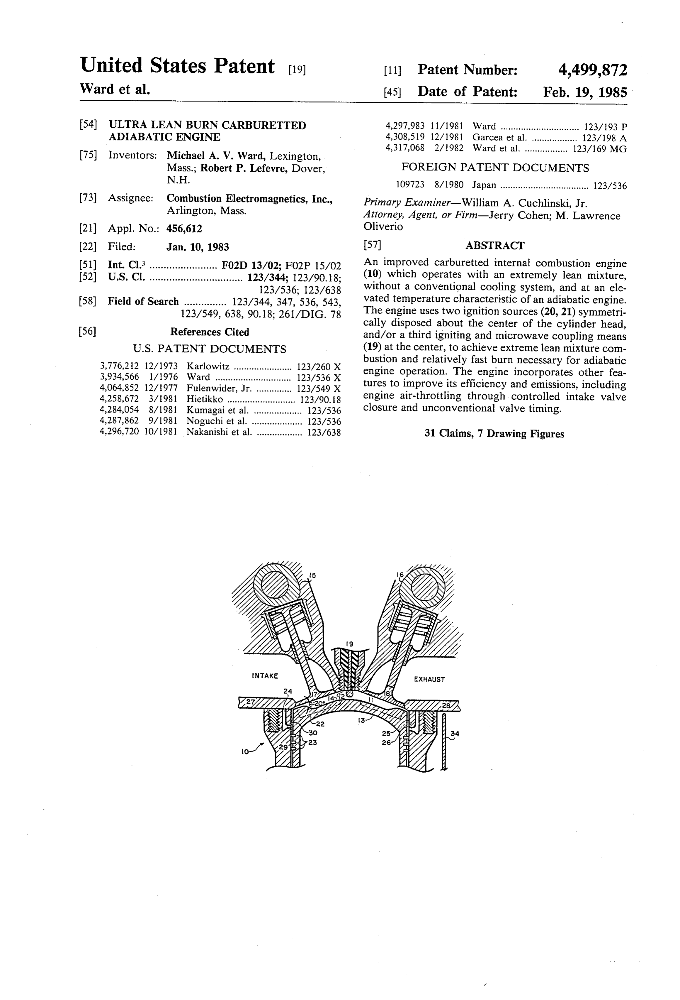
The nature and objects of the invention are illustrated ume ratio, as long as a stable microwave mode can be and described in reference to the following drawings, maintained near TDC.
which also illustrate the preferred embodiments of the 10 Two spark plugs 20 and 21 are used for the following invention: reasons: to reduce the burn path (and hence burn time), FIG. 1 depicts the end (lateral) view of one cylinder and to present symmetrical ignition electrical dis of the preferred embodiment of the improved engine charges to the microwaves, to reduce microwave re invention, depicting most of the operational features of flection (which is also reduced through squish dis the improved engine, including cams and valves, cylin 15 charge dissipating effects). The plugs are used to pro der head and upper cylinder sleeve, and upper part of duce a higher current discharge such as is found in the piston; plasma jet ignition (See Ward and Wu, U.S. Pat. No. FIG. 1A is a cross-sectional top view of the cylinder 4,317,068).
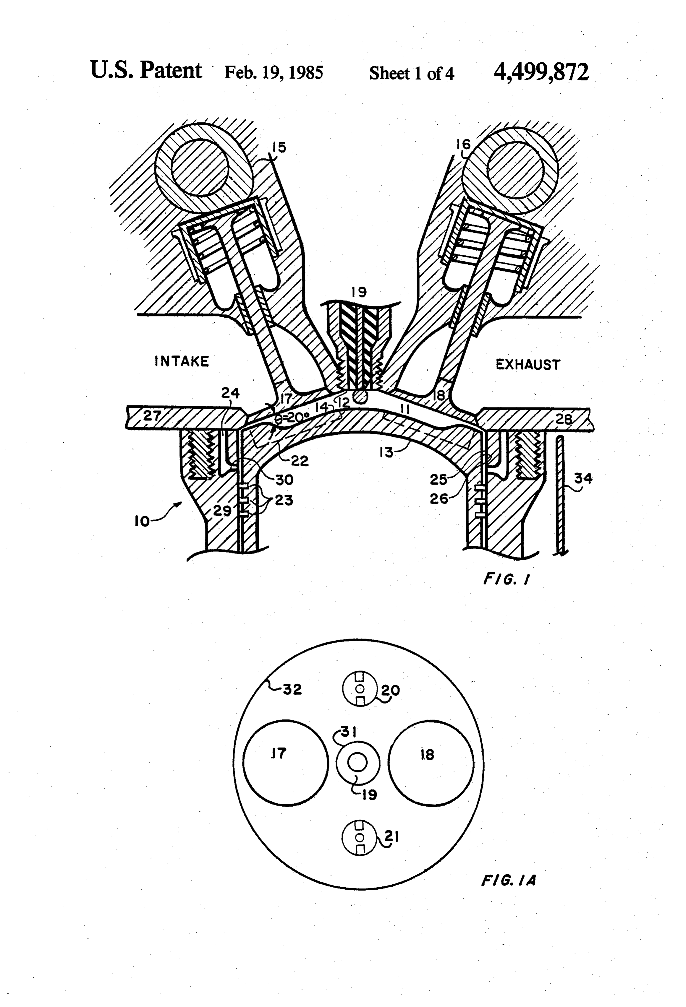
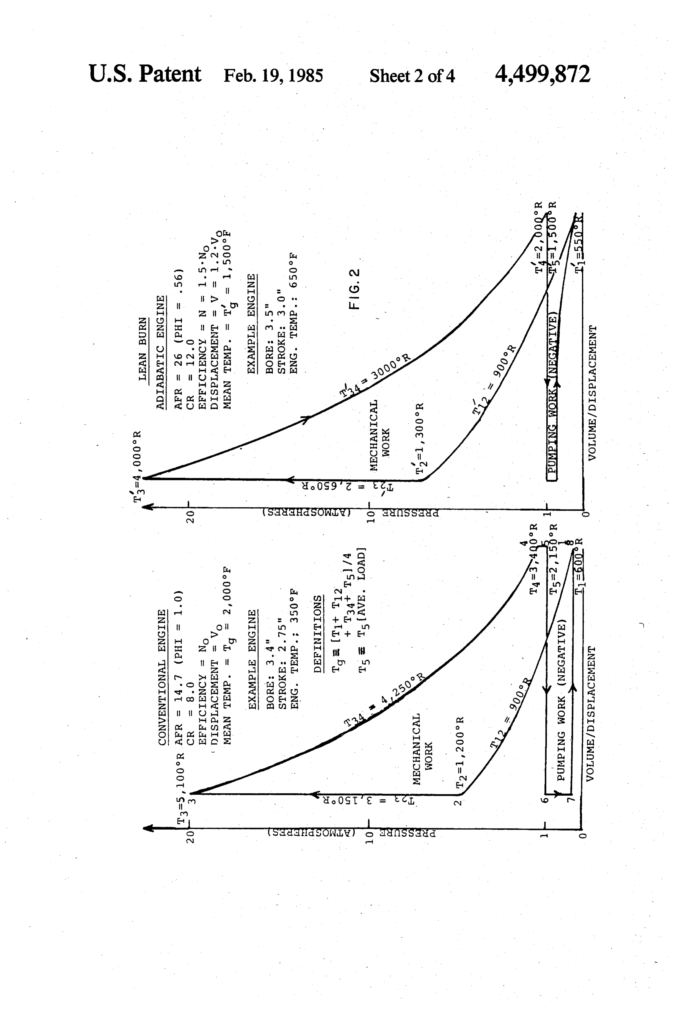
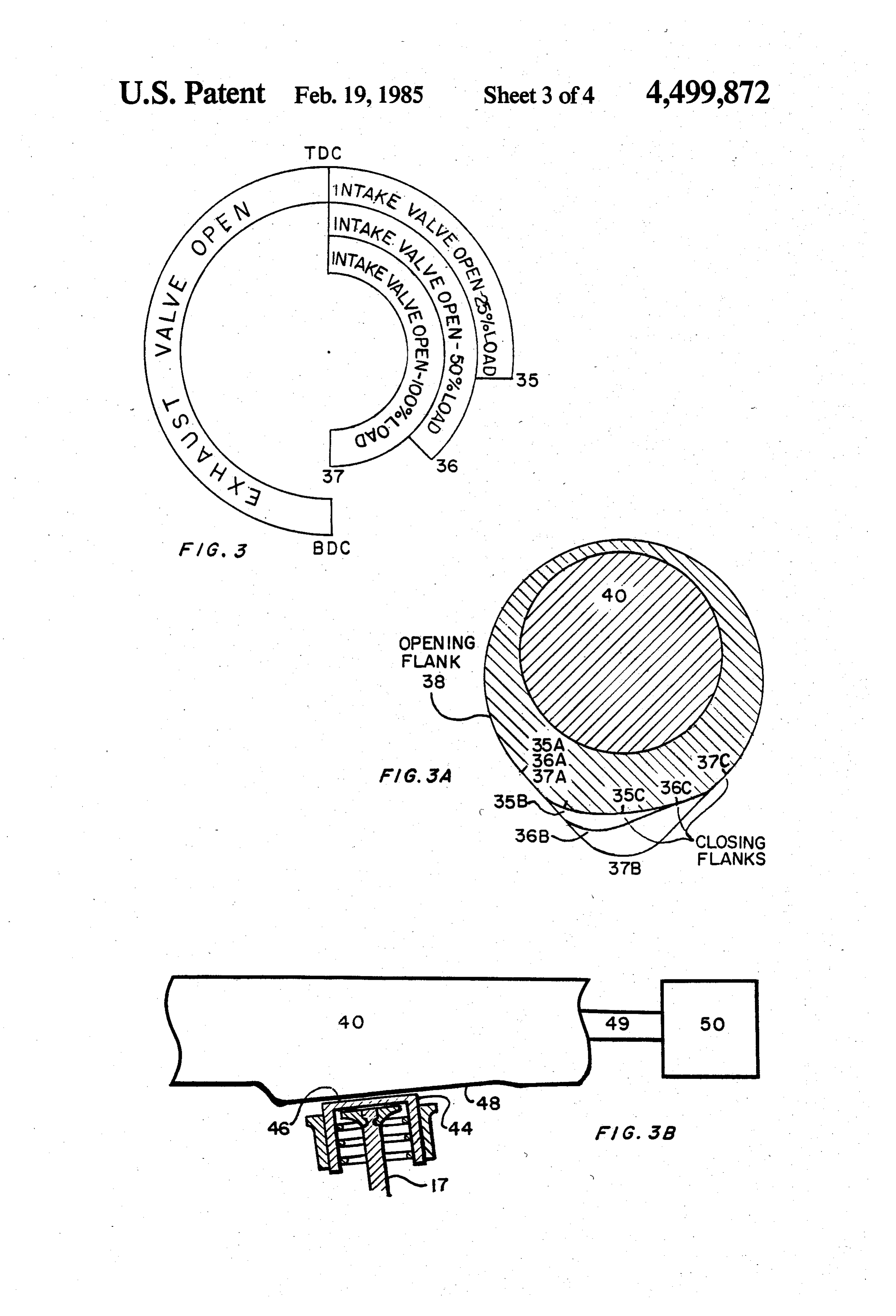
head, showing valves, spark plugs and microwave cou A heat insulating layer (possibly ceramic)24 is placed pler; 20 at the topmost part of the cylinder sleeve (and can be FIG.2 depicts ideal operating P-V cycles (Pressure placed elsewhere) to reduce the radial heat conductiv Volume diagrams) for conventional engines and for the ity (heat transfer) of this region and enhance its fast present improved engine invention. warm-up. The insulating layer 24 can also serve as a FIG. 3 is a circle diagram depicting preferred valve microwave choke by introducing a horizontal channel operation; 25 30 shown in the figure as long microwave excitation is FIG. 3A is an end view depicting three cross-sec limited to less than 30 either side of TDC (in Ward, tional slices of the tapered can used for controlling U.S. Pat. No. 4,297,983 the choke is shown placed in the intake valve closure; piston). The channel can have small solid metallic sec FIG. 3B is a side view of the CIVC showing one tions, where it intersects the interior cylinder wall 25, as section (for one cylinder) of the can and the upper part 30 a way of helping retain the ceramic in place without of the valve mechanism. destroying choke action. Note that the rings 23 are FIG. 4 is a schematic of an advanced (feedback loop) placed below the level of the choke (about i' to ' cam actuator and engine controller. below the cylinder head) so that they do not interfere
DESCRIPTION OF THE PREFERRED
with choke action. Also, if oil lubrication is used (pref.
35 erably synthetic), then locating the rings 23 in this way
EMBODIMENTS helps keep the oil (film) away from the hotter surfaces FIG. 1 depicts the preferred embodiment of the en 12, 14, 25 and 26. The piston and cylinder surfaces 12 gine apparatus 10 of the invention, composed of a semi and 14 would be preferably composed of Stainless Steel spherical (conical) combustion chamber 11 with an (SS) or iron-nickel alloy (Fe-Ni), or other such material included angle 0 of 18 to 24 with respect to the hori to handle the higher temperatures. The relatively low zontal (6=20 here), said chamber being defined by the thermal conductivity of these materials (SS has a ther cylinder head 12, the piston face 14 (of piston 13) and mal conductivity about a tenth of Aluminum) reduces the upper surface 25 of the cylinder sleeve 29. The heat transference to improve the engine's adiabatic design includes double overhead cams 15 and 16 to properties without having to overly depend on ceram provide independent control of the valves 17 and 18 (to 45 ics. These two thermal properties also suggest the con achieve controlled intake valve closure of intake valve struction of the exhaust manifold 28 out of SS (for fast 17). This semi-spherical design is chosen because it warm-up and higher operating temperature). provides room for the centrally located microwave From the microwave point of view the use of, for probe coupler 19, since the cam/valve mechanisms example a SS combustion chamber would be highly locate outwards and away from each other. It also pro 50 desirable because SS also has a very low electrical con vides naturally improved breathing because of the bet ductivity (about a twentieth of Aluminum). This has ter air-flow pattern and relatively larger area it provides two positive consequences. First it implies that the for valves, compensating in part for the smaller valves empty combustion chamber would have a relatively necessitated by the presence of the coupler 19. It also low Q (electrical Quality Factor) of about 300 to 600, allows for the placement of the two spark plugs 20 and 55 improving the ability to effectively couple microwaves 21 (FIG. 1A) without having them interfere with cou to the combustion chamber throughout the entire com pler 19 or the spark plugs of the adjacent cylinder. The bustion process (including prior to combustion if so included angle 0 is picked to satisfy the above men desired). Secondly, the low electrical conductivity tioned spatial constraints and to minimize the surface to means that a layer of thickness equal to several skin volume ratio. The combustion chamber does not have 60 depths (about 0.001' one mil) would be heated by the to be circularly symmetric (the piston valve cut-outs microwaves, further stimulating the combustion by already destroy the perfect symmetry). reducing the wall quenching effects. This factor could The piston surface shape 14 is of the "Mexican Hat” be enhanced by constructing a piston and/or cylinder variety, with the side rim or lobe 22 introduced to help with about 0.001" SS on a ceramic backing (by flame stabilize the resonant frequency of the lowest order 65 spraying techniques, for example) so that a more intense microwave mode contemplated here (See Ward, U.S. heating (higher temperature) of the surface layer can be Pat. No. 4,297,983), and to produce radial squish near achieved (through reduced heat transference from it) to top dead center (TDC). The squish serves to spread the reduce wall quenching effects.
Page 8
Most of the engine would be surrounded by heat ventional valve timing. These thermal considerations retaining and controlling shields 34 for the purpose of are contrary to the conventional wisdom on proper achieving some temperature control of the surrounding engine operation.
air, by means of small electric fans. In this way tempera FIG. 2 shows real gas, ideal operating cycles for the ture sensitive areas (where electronics for example, are 5 "conventional standard' and improved engine, with the contained) can be kept at close to under-hood ambient differences between the two engine operating modes temperatures, and other areas allowed to achieve high described in terms of these curves. The curves also aid est practical temperatures for more optimal adiabatic in the description of the two engines under non-ideal engine operation. cycle operating conditions, expecially in describing the FIG. 1A depicts the inside cross-sectional view of the 10 effects of the highly unconventional valve timing used cylinder head of FIG. 1. The microwave probe coupler in the improved engine. The temperatures shown (in 19 is in the center, and the spark (or plasma jet) plugs 20, general are accurate to better than 10% and) are used 21 are located approximately half-way between the primarily for bringing out the differences between the edge 31 of the probe coupler 19 and the cylinder wall 32 two engines.
(the upper edge of 25, FIG. 1). The valves 17 and 18 are 15 Beginning with the cycle starting point 1, we note located between the coupler 19 and the cylinder wall that TdT1. The difference is due primarily to the 32. The orientation of the intake valve 17 is different different exhaust gas residual for the two different com from that of the exhaust valve 18 because of the require pression ratios, and because of the expansion cooling of ment to achieve "controlled intake valve closure' the improved engine's CIVC operation under part load. (CIVC) as a way of controlling engine air-throttling 20 Precombustion temperatures reverse (T2 <T) because with minimum pumping losses. This is discussed fully of the greater adiabatic heating (temperature rise) from with reference to FIG. 3. The need and advantages of the higher compression ratio of the improved engine. CIVC will become apparent in the following discussion The peak (post combustion) temperatures T3, T3 of the P-V diagrams of FIG. 2. differ considerably; the improved engine has a peak FIG. 2 depicts idealized P-V diagrams for a conven-25 operating temperature T3 of approximately 1,000 F. tional engine and for the present improved engine in lower than T3 (F. =R-460), eliminating NOx emis vention. The "Conventional standard' engine is as sions for practical purposes in its case, and reducing its sumed to operate at stoichiometric air-fuel ratio (of 14.7 peak pressure so that it is comparable to the conven to 1 or d = 1) and at a compression ratio of 8 to 1 (lim tional engine (despite the substantially higher compres ited by engine knock and NOx emissions) with no ex- 30 sion ratio of the improved engine). The average expan haust gas recirculation (EGR). The improved engine sion temperature T34 (average of T3 and T4) is seen to be operates at around 26 to 1 air-fuel ratio (d = 0.6) and at 1,250 F. less (than T34) for the improved engine (be a compression (expansion)ratio of 12 to 1. cause of the substantially higher air-fuel ratios and ex In comparing these P-V curves, the following ap pansion ratios), leading to the substantially reduced heat proximations (for lean mixtures) should be appreciated 35 losses and hence to the efficiency increase summarized and kept in mind: in Table 1. Similarly, the exhaust temperatures T4, T5 Flame speed S-S-Tu2.5/Puo.25 where Tu, Pu are are substantially lower for the improved engine, which the unburnt gas temperature and pressure respec helps in part to compensate for the higher engine (block tively, and Suois the ambient temperature and pres or cylinder) temperature in controlling underhood tem sure flame speed. 40 peratures. T'sensitive to load (unlike the other tempera With regard to microwave enchancement of combus tures) and is shown here for an average load setting. tion, the following very approximate relationship The lower the load setting, the lower Tis, because of can be made (for Propane): the greater degree of expansion cooling that occurs Suoad -0.53 meters/sec. upon opening of the exhaust valve (represented by the Suomal-d-0.43 meters/sec. 45 process 4-5). The most important and striking difference where d = Equivalence ratio=Stoichiometric air between the two engines is their mean temperatures Tg, fuel ratio/Actual air-fuel ratio). Tg. Mean combustion temperatures are defined in sev and Suo" is the microwave enhanced flame speed. eral ways, and the following definition has been chosen The effect of the microwaves is being modeled as for the present purposes:
reducing the lean flammability from 0.53 to 0.43, 50 and increasing the flame speed by progressively larger amounts as the normal lean limit is ap proached. The above relationships hold for dis 1. One important characterization of the improved engine Curves demonstrating these results are given in (the CEI Lean Burn Adiabatic Engine) is that it has an Ward, Journal of Microwave Power, (3), 1980. 55 ideal cycle mean gas temperature Tg approximately An immediate conclusion that can be drawn is that in operating near an air-fuel ratio of 26 to 1 (d=0.6), we three gine, quarters that of the "conventional standard' en i.e. Tgs.T. We can place bounds on the definition are operating in a range where the unstimulated flame of “approximately three quarters' according to the burns very slowly if at all. Preignition with such a mix following:
ture is practically impossible, making adiabatic opera- 60 tion now possible. Moreover, to obtain proper flame is Tg/Ts 4/5.
propagation, one must stimulate the flame both electri cally (with microwaves) and thermally. (Thermal stin Another important difference is that in the improved ulation is achieved by providing maximum precombus engine the exhaust pressure PA is close to atmospheric at tion unburnt gas temperatures through heat transfer- 65 low to moderate loads, because of the very lean mixture ence from elevated operating temperature engine sur and moderately high expansion ratio. At the 0.25 load faces and through greater adiabatic heating through setting shown, P4 is almost exactly one atmosphere higher compression ratio operation, and through uncon (representing a complete expansion cycle, which is the
Page 9
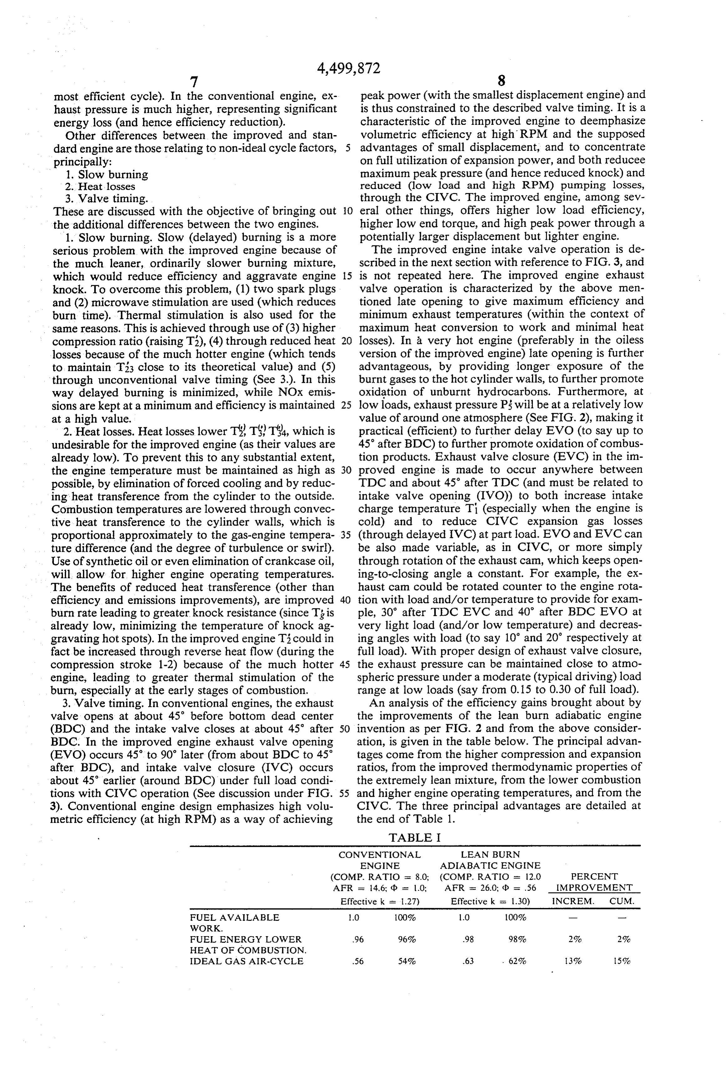
most efficient cycle). In the conventional engine, ex peak power (with the smallest displacement engine) and haust pressure is much higher, representing significant is thus constrained to the described valve timing. It is a energy loss (and hence efficiency reduction). characteristic of the improved engine to deemphasize Other differences between the improved and stan volumetric efficiency at high RPM and the supposed dard engine are those relating to non-ideal cycle factors, 5 advantages of small displacement, and to concentrate principally: on full utilization of expansion power, and both reducee 1. Slow burning maximum peak pressure (and hence reduced knock) and 2. Heat losses reduced (low load and high RPM) pumping losses, 3. Valve timing. through the CIVC. The improved engine, among sev These are discussed with the objective of bringing out O eral other things, offers higher low load efficiency, the additional differences between the two engines. higher low end torque, and high peak power through a 1. Slow burning. Slow (delayed) burning is a more potentially larger displacement but lighter engine. serious problem with the improved engine because of The improved engine intake valve operation is de the much leaner, ordinarily slower burning mixture, scribed in the next section with reference to FIG. 3, and which would reduce efficiency and aggravate engine 15 is not repeated here. The improved engine exhaust knock. To overcome this problem, (1) two spark plugs valve operation is characterized by the above men and (2) microwave stimulation are used (which reduces tioned late opening to give maximum efficiency and burn time). Thermal stimulation is also used for the minimum exhaust temperatures (within the context of same reasons. This is achieved through use of (3) higher maximum heat conversion to work and minimal heat compression ratio (raising T3), (4) through reduced heat 20 losses). In a very hot engine (preferably in the oiless losses because of the much hotter engine (which tends version of the improved engine) late opening is further to maintain T33 close to its theoretical value) and (5) advantageous, by providing longer exposure of the through unconventional valve timing (See 3.). In this burnt gases to the hot cylinder walls, to further promote way delayed burning is minimized, while NOx emis oxidation of unburnt hydrocarbons. Furthermore, at sions are kept at a minimum and efficiency is maintained 25 low loads, exhaust pressure P5 will be at a relatively low at a high value. value of around one atmosphere (See FIG. 2), making it 2. Heat losses. Heat losses lower T3, TST34, which is practical (efficient) to further delay EVO (to say up to undesirable for the improved engine (as their values are 45 after BDC) to further promote oxidation of combus already low). To prevent this to any substantial extent, tion products. Exhaust valve closure (EVC) in the im the engine temperature must be maintained as high as 30 proved engine is made to occur anywhere between possible, by elimination of forced cooling and by reduc TDC and about 45 after TDC (and must be related to ing heat transference from the cylinder to the outside. intake valve opening (IVO)) to both increase intake Combustion temperatures are lowered through convec charge temperature Ti (especially when the engine is tive heat transference to the cylinder walls, which is cold) and to reduce CIVC expansion gas losses proportional approximately to the gas-engine tempera 35 (through delayed IVC) at part load. EVO and EVC can ture difference (and the degree of turbulence or swirl). be also made variable, as in CIVC, or more simply Use of synthetic oil or even elimination of crankcase oil, through rotation of the exhaust cam, which keeps open will allow for higher engine operating temperatures. ing-to-closing angle a constant. For example, the ex The benefits of reduced heat transference (other than haust cam could be rotated counter to the engine rota efficiency and emissions improvements), are improved 40 tion with load and/or temperature to provide for exam burn rate leading to greater knock resistance (since Tg is ple, 30° after TDC EVC and 40° after BDC EVO at already low, minimizing the temperature of knock ag very light load (and/or low temperature) and decreas gravating hotspots). In the improved engine T3 could in ing angles with load (to say 10 and 20 respectively at fact be increased through reverse heat flow (during the full load). With proper design of exhaust valve closure, compression stroke 1-2) because of the much hotter 45 the exhaust pressure can be maintained close to atmo engine, leading to greater thermal stimulation of the spheric pressure under a moderate (typical driving) load burn, especially at the early stages of combustion. range at low loads (say from 0.15 to 0.30 of full load). 3. Valve timing. In conventional engines, the exhaust An analysis of the efficiency gains brought about by valve opens at about 45° before bottom dead center the improvements of the lean burn adiabatic engine (BDC) and the intake valve closes at about 45 after 50 invention as per FIG. 2 and from the above consider BDC. In the improved engine exhaust valve opening ation, is given in the table below. The principal advan (EVO) occurs 45 to 90' later (from about BDC to 45° tages come from the higher compression and expansion after BDC), and intake valve closure (IVC) occurs ratios, from the improved thermodynamic properties of about 45' earlier (around BDC) under full load condi the extremely lean mixture, from the lower combustion tions with CIVC operation (See discussion under FIG. 55 and higher engine operating temperatures, and from the 3). Conventional engine design emphasizes high volu CIVC. The three principal advantages are detailed at metric efficiency (at high RPM) as a way of achieving the end of Table 1.
TABLE I
CONVENTIONAL LEAN BURN
ENGINE ADIABATIC ENGINE
Effective k = 1.27) Effective k = 1.30) INCREM, CUM.
FUEL AVAILABLE O 100% 1.0 100%
WORK
FUEL ENERGY LOWER 96. 96% .98 98% 2% 2%
HEAT OF COMBUSTION.
IDEAL GAS AIR-CYCLE 56. 54% .63 . 62% 3% 5%
Page 10
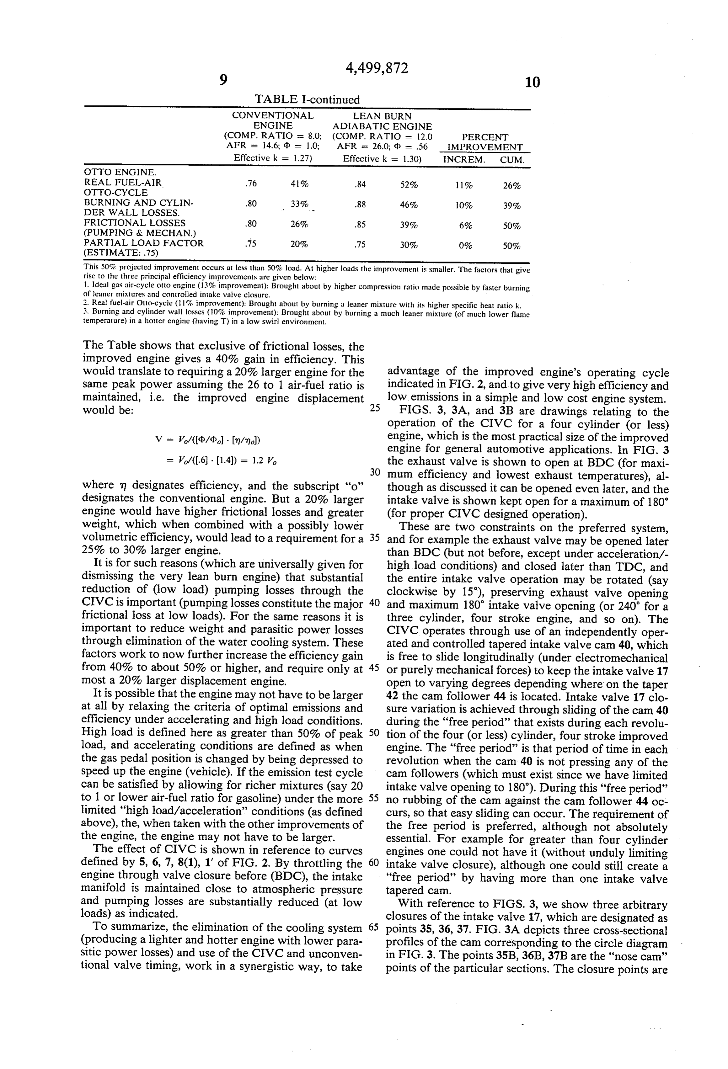
TABLE I-continued
CONVENTIONAL LEAN BURN
ENGINE ADIABATIC ENGINE
(COMP. RATIO = 8.0; (COMP. RATIO = 12.0 PERCENT
AFR - 14.6; d = 1.0, AFR = 26.0; d = .56 IMPROVEMENT
Effective k = 1.27) Effective k = 1.30) INCREM, CUM.
OTTO ENGINE.
REAL FUEL-AIR .76 41% .84 52% 11% 26%
BURNING AND CYLN- 80 33% .88 46% 0% 39% DER WALL LOSSES. -
FRCTIONAL LOSSES 80 26% .85 39% 6% 50%
(PUMPING & MECHAN.)
PARTIAL LOAD FACTOR 75 20% 75 30% 0% 50%
(ESTIMATE: .75)
This 50% projected improvement occurs at less than 50% load. At higher loads the improvement is smaller. The factors that give rise to the three principal efficiency improvements are given below:
1. Ideal gas air-cycleotto engine (13% improvement): Brought about by higher compression ratio made possible by faster burning of leaner mixtures and controlled intake valve closure.
2. Real fuel-air Otto-cycle (1% improvement): Brought about by burning a leaner mixture with its higher specific heat ratio k. 3. Burning and cylinder wall losses (10% improvement): Brought about by burning a much leaner mixture (of much lower flame temperature) in a hotter engine (having T) in a low swirl environment.
The Table shows that exclusive of frictional losses, the improved engine gives a 40% gain in efficiency. This would translate to requiring a 20% larger engine for the advantage of the improved engine's operating cycle same peak power assuming the 26 to 1 air-fuel ratio is indicated in FIG. 2, and to give very high efficiency and maintained, i.e. the improved engine displacement low emissions in a simple and low cost engine system. would be: 25 FIGS. 3, 3A, and 3B are drawings relating to the operation of the CIVC for a four cylinder (or less)
Vo/((d/d). Im/mol)) engine, which is the most practical size of the improved engine for general automotive applications. In FIG. 3
V/(.6 - 1.4) = 1.2 Vo the exhaust valve is shown to open at BDC (for maxi 30 mum efficiency and lowest exhaust temperatures), al where m designates efficiency, and the subscript "o' though as discussed it can be opened even later, and the designates the conventional engine. But a 20% larger intake valve is shown kept open for a maximum of 180 engine would have higher frictional losses and greater (for proper CIVC designed operation). weight, which when combined with a possibly lower These are two constraints on the preferred system, volumetric efficiency, would lead to a requirement for a 35 and for example the exhaust valve may be opened later 25% to 30% larger engine. than BDC (but not before, except under acceleration/- It is for such reasons (which are universally given for high load conditions) and closed later than TDC, and dismissing the very lean burn engine) that substantial the entire intake valve operation may be rotated (say reduction of (low load) pumping losses through the clockwise by 15), preserving exhaust valve opening CIVC is important (pumping losses constitute the major 40 and maximum 180 intake valve opening (or 240 for a frictional loss at low loads). For the same reasons it is three cylinder, four stroke engine, and so on). The important to reduce weight and parasitic power losses CIVC operates through use of an independently oper through elimination of the water cooling system. These ated and controlled tapered intake valve cam 40, which factors work to now further increase the efficiency gain is free to slide longitudinally (under electromechanical from 40% to about 50% or higher, and require only at 45 or purely mechanical forces) to keep the intake valve 17 most a 20% larger displacement engine. open to varying degrees depending where on the taper It is possible that the engine may not have to be larger 42 the cam follower 44 is located. Intake valve 17 clo at all by relaxing the criteria of optimal emissions and sure variation is achieved through sliding of the cam 40 efficiency under accelerating and high load conditions. during the "free period' that exists during each revolu High load is defined here as greater than 50% of peak 50 tion of the four (or less) cylinder, four stroke improved load, and accelerating conditions are defined as when engine. The "free period' is that period of time in each the gas pedal position is changed by being depressed to revolution when the cam 40 is not pressing any of the speed up the engine (vehicle). If the emission test cycle cam followers (which must exist since we have limited can be satisfied by allowing for richer mixtures (say 20 intake valve opening to 180'). During this "free period” to 1 or lower air-fuel ratio for gasoline) under the more 55 no rubbing of the cam against the cam follower 44 oc limited "high load/acceleration' conditions (as defined curs, so that easy sliding can occur. The requirement of above), the, when taken with the other improvements of the free period is preferred, although not absolutely the engine, the engine may not have to be larger. essential. For example for greater than four cylinder The effect of CIVC is shown in reference to curves engines one could not have it (without unduly limiting defined by 5, 6, 7, 8(1), 1' of FIG. 2. By throttling the 60 intake valve closure), although one could still create a engine through valve closure before (BDC), the intake "free period' by having more than one intake valve manifold is maintained close to atmospheric pressure tapered cam.
and pumping losses are substantially reduced (at low With reference to FIGS. 3, we show three arbitrary loads) as indicated. closures of the intake valve 17, which are designated as To summarize, the elimination of the cooling system 65 points 35, 36, 37. FIG. 3A depicts three cross-sectional (producing a lighter and hotter engine with lower para profiles of the cam corresponding to the circle diagram sitic power losses) and use of the CIVC and unconven in FIG. 3. The points 35B, 36B, 37B are the "nose cam” tional valve timing, work in a synergistic way, to take points of the particular sections. The closure points are
Page 11
shown as 35C, 36C, 37C. Note that the normal (closed shaft 41 or the controller results in reducing the power throttle or off) position of the cam is with the cam fol output of the engine i.e. using the opposite taper to the lower 44 all the way on the right of the cam 40 shown one shown in FIG. 3B.
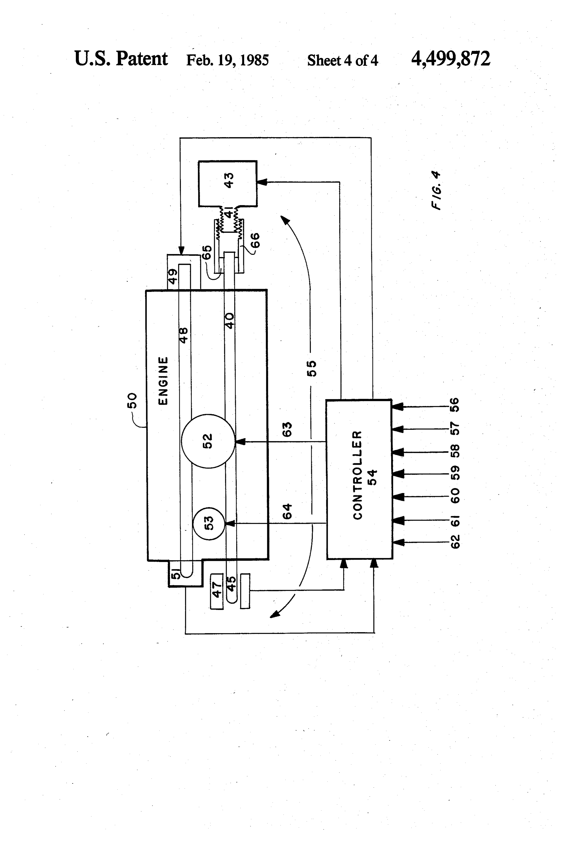
in FIG. 3B, giving minimum intake valve opening dura FIG. 4 is a schematic of a more advanced (feedback tion. This has the important advantage (over conven loop) cam actuator (and other controller) circuit 55. tional throttling) in that under cranking conditions, the Fifty (50) is a schematic representation of the engine cylinder pressure is at its lowest level in this case (at the with carburettor 52 and ignition and flame stimulation lowest load position), making for easy cranking, espe system 53. Forty (40) and 48 are the intake valve cam cially under severe conditions, such as very cold days and exhaust valve cam respectively. The three main when battery voltage is low. CIVC thus also makes 10 elements making up the feedback loop circuit are the more electrical power available during cranking to controller 54, the actuators 43/49 and the position/rota drive the ignition and flame stimulation electrical tion sensors 47/51. The controller 54 performs signal power supplies, eliminating the need for a larger battery comparison to a system transfer function, or performs a and simplifying ignition system design. In conventional calculation to a system transfer function from the input throttling, cranking speeds are too low to allow the 15 sensor data.
throttle plate to be effective (because of the very low In its simplest form, the circuit 55 uses a mechanical air-flow velocities), so that cranking occurs against (independent variable) can actuator as described with almost peak pressure (equal to wide open throttle). reference to FIG. 3B, and does not use sensors 47/51 for With reference to FIG. 3A, it is noted that the cam is feedback control. The controller 54 receives input sig tapered to give constant valve opening; it clearly could 20 nals which sense the gas pedal position, 56 (the principal be tapered to give non-constant opening. For example, controlling variable), engine speed (RPM) 57, engine a slight taper can be placed on the opening flank 38 so temperature 58, intake-air temperature 59, intake mani that the valve opening advances with load requirement, fold vacuum 60, knock-detection 61, and possibly oth from say 30 after TDC at light load to 10 after TDC ers. It processes these by means of a predetermined at full load. Furthermore, IVO variation can be syn 25 transfer function programmed in the controller 54 and chronized with EVC for optimal operation. IVO can provides outputs to vary air-fuel mixture (output 63), also be retarded with load, if required, by for example, spark timing and electromagnetic stimulator (output 64) rotating the cam (with respect to the crank) in synchro exhaust valve opening and closure variation (output 65), nization with EVC. and possibly others. It can sample these input variables FIG. 3B is a 90° rotation of FIG. 1 about a vertical 30 at a rate of, for example, one per milisecond. axis. It is noted that the face 46 of the cam follower 44 In this form, the system is subject to errors due to is parallel to the taper face 42, while the exhaust valve mechanical machining tolerances, assembly and me is vertical. This is required to eliminate undue wear chanical wear of parts. These can be eliminated through between these two surfaces 46 and 42, and creates the feedback from position and/or other sensors, such as added complication of slightly unsymmetric intake 17 35 the linear differential transformer sensor 47 connected and exhaust 18 valves with respect to the cylinder axis. to the output shaft 45 of the intake valve cam 40. The For a single cylinder engine the symmetry can be pre sensor 47 is especially suitable since it does not require served and the intake valve cam 40 itself angled to make physical contact with what may be a hot camshaft 40. 42 parallel to 44, which would now be horizontal. It is simply a special transformer connected to a phase The cam 40 is actuated (moved axially) by means of 40 comparator circuit, which gives a phase angle output the cam actuator 43. In its simplest form, 43 is a mechan for example, (between two square waves) as a function ical linkage mechanism connected to the vehicle gas of cam 45 position (penetration into the winding (47)). pedal; in more advanced form, it is an electromechani This information is fed back into controller 54, which cal actuator, which is described more fully with refer then, by means of comparator circuits, can insure that ence to FIG. 4. The cam actuator 43 slides cam 40 by 45 the cam is positioned as required. Other feedback sen means of shaft 41 (through a bearing mechanism as the sors, such as exhaust can rotational sensor 51 can be cam is rotating), to adjust the mass of air/fuel mixture used, to feedback-control (through actuator 49) the entering the cylinder. As shown in FIG. 3B, motion exhaust cam, and other engine variables. from right to left (pushing of the cam 40 by shaft 41) The most advanced (electronic) system is one represents motion producing earlier valve closing (ligh 50 whereby the actuator 43 and shaft 41 are electro terload). In this mode, the can 40 could be operated by mechanical. In particular, 43 represents a stepping having it spring loaded at the left-most end with a motor connected to the shaft 41, by means of, for exam Spring under compression, with appropriate spring con ple, a bearing 65 and wormgear 66, to provide motion to stant to be able to move the cam if no obstruction is the cam. A shock absorbing part (which is possibly also placed at the right. The shift 41 and linkage mechanism 55 thermally insulating) may have to be interposed be then controls the axial motion by acting as a stop, with tween motor 43 and shaft 41 to handle the non-con the fully extended (left-most position) of the shaft being tinuity of the cam "free period' (if it exists) and its the light load position, and higher loads being obtained possible high temperature. The advantages of the con by pulling on shaft 41. By reversing the taper (and valve troller 54 and stepping motor 43 combination is that it orientation), higher loads are achieved by pushing on 60 allows for other than simple linear relationships be shaft 41. In this case, one can spring load the cam tween gas pedal position and cam axial position, as well (through a roller bearing) with a spring not sufficient to as eliminating the requirement for possibly very large move the cam, but sufficiently so that with light pres pedal. pressure to actuate the can and/or spring assists sure from shaft 41, the cam 40 will slide. Other combi (as described in reference to FIG. 3B.) nations of the type described are clearly also possible. 65 It is within the context of the invention that the intake For use in an automobile or other application in and exhaust valves can be controlled independently or which safety may be an issue, the taper and spring load in synchronization, and that either linear tapered cam ing should always be arranged so that a failure of the means or can rotation means (relative to the engine
Page 12
crank) be used in any combination or permutation to means for effecting such linear cam movement, as a achieve optimal engine operation with respect to effi function of engine load.
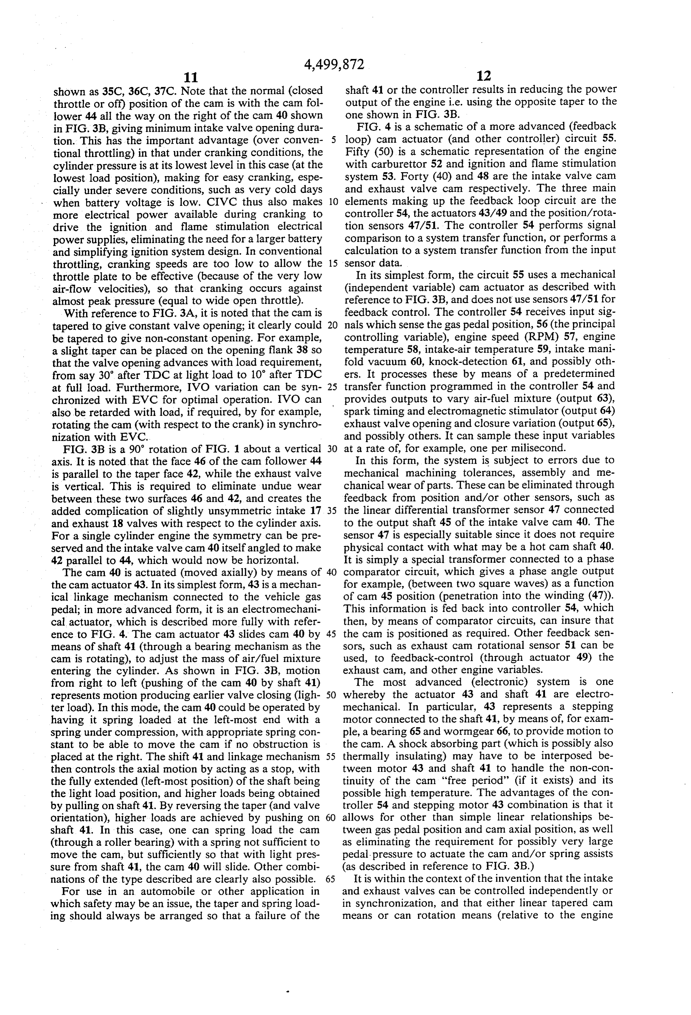
ciency, emissions, power, cost and simplicity. Other 4. Internal combustion engine apparatus in accor direct means, such as electromechanical or hydraulic dance with claim 3, wherein intake valve opening is means to control valve timing, are also within the con limited to a maximum of less than 720°/n, where n is the text of the invention. number of engine cylinders of a four stroke engine (180° In addition most of the principles described herein for a four cylinder, four stroke engine-the typical with regard to ultra lean, elevated temperature, high engine), such condition defining a free period during expansion ratio operation can be applied to a two stroke which there is no loading of the valves by the cam/- IC engine, where emissions would be emphasized to a O spring combination, said free period defining the time greater extent (the two stroke engine's principal prob during which linear axial movement of the tapered cam lem) since power to weight ratio of a two stroke is is effected for changing load settings. already high. 5. Internal combustion engine apparatus in accor Since certain changes may be made in the above dance with claim 4, wherein axial movement of the apparatus and method without departing from the 15 tapered cam is produced through mechanical linkage to scope of the invention herein involved, it is intended the vehicle gas pedal, such axial movement also being that all matter contained in the above description, or coupled to air/fuel mixing means, ignition and flame shown in the accompanying drawings shall be inter stimulating means, and exhaust valve control means, to preted in an illustrative and not in a limiting sense. vary these in a predetermined and prescribed way with What is claimed is: 20 axial movement of the cam.
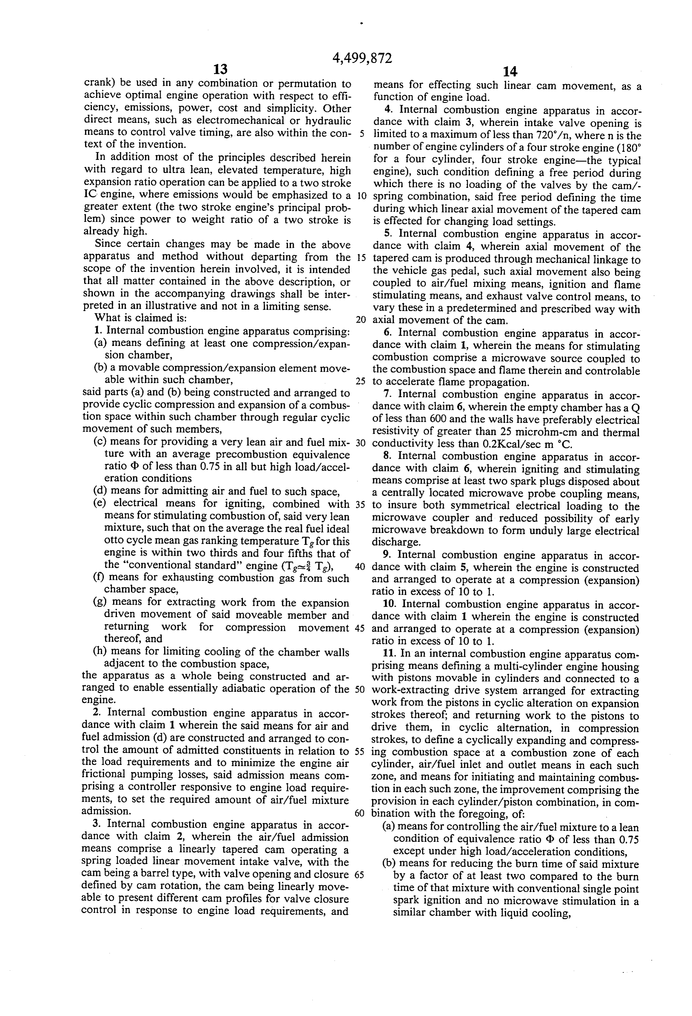
1. Internal combustion engine apparatus comprising: 6. Internal combustion engine apparatus in accor (a) means defining at least one compression/expan dance with claim 1, wherein the means for stimulating sion chamber, combustion comprise a microwave source coupled to (b) a movable compression/expansion element move the combustion space and flame therein and controlable able within such chamber, 25 to accelerate flame propagation.
said parts (a) and (b) being constructed and arranged to 7. Internal combustion engine apparatus in accor provide cyclic compression and expansion of a combus dance with claim 6, wherein the empty chamber has a Q tion space within such chamber through regular cyclic of less than 600 and the walls have preferably electrical movement of such members, resistivity of greater than 25 microhm-cm and thermal (c) means for providing a very lean air and fuel mix 30 conductivity less than 0.2Kcal/sec m C. ture with an average precombustion equivalence 8. Internal combustion engine apparatus in accor ratio d of less than 0.75 in all but high load/accel dance with claim 6, wherein igniting and stimulating eration conditions means comprise at least two spark plugs disposed about (d) means for admitting air and fuel to such space, a centrally located microwave probe coupling means, (e) electrical means for igniting, combined with 35 to insure both symmetrical electrical loading to the means for stimulating combustion of, said very lean microwave coupler and reduced possibility of early mixture, such that on the average the real fuel ideal microwave breakdown to form unduly large electrical otto cycle mean gas ranking temperature T for this discharge.
engine is within two thirds and four fifths that of 9. Internal combustion engine apparatus in accor the "conventional standard" engine (Tall: Tg), 40 dance with claim 5, wherein the engine is constructed (f) means for exhausting combustion gas from such and arranged to operate at a compression (expansion) chamber space, ratio in excess of 10 to 1.
(g) means for extracting work from the expansion 10. Internal combustion engine apparatus in accor driven movement of said moveable member and dance with claim 1 wherein the engine is constructed returning work for compression movement 45 and arranged to operate at a compression (expansion) thereof, and ratio in excess of 10 to 1.
(h) means for limiting cooling of the chamber walls 11. In an internal combustion engine apparatus com adjacent to the combustion space, prising means defining a multi-cylinder engine housing the apparatus as a whole being constructed and ar with pistons movable in cylinders and connected to a ranged to enable essentially adiabatic operation of the 50 work-extracting drive system arranged for extracting engine. work from the pistons in cyclic alteration on expansion 2. Internal combustion engine apparatus in accor strokes thereof; and returning work to the pistons to dance with claim 1 wherein the said means for air and drive them, in cyclic alternation, in compression fuel admission (d) are constructed and arranged to con strokes, to define a cyclically expanding and compress trol the amount of admitted constituents in relation to 55 ing combustion space at a combustion zone of each the load requirements and to minimize the engine air cylinder, air/fuel inlet and outlet means in each such frictional pumping losses, said admission means com zone, and means for initiating and maintaining combus prising a controller responsive to engine load require tion in each such zone, the improvement comprising the ments, to set the required amount of air/fuel mixture provision in each cylinder/piston combination, in com admission. 60 bination with the foregoing, of: 3. Internal combustion engine apparatus in accor (a) means for controlling the air/fuel mixture to a lean dance with claim 2, wherein the air/fuel admission condition of equivalence ratio d of less than 0.75 means comprise a linearly tapered cam operating a except under high load/acceleration conditions, spring loaded linear movement intake valve, with the (b) means for reducing the burn time of said mixture cam being a barrel type, with valve opening and closure 65 by a factor of at least two compared to the burn defined by cam rotation, the cam being linearly move time of that mixture with conventional single point able to present different cam profiles for valve closure spark ignition and no microwave stimulation in a control in response to engine load requirements, and similar chamber with liquid cooling,
Page 13
(c) means for retaining heat left in the combustion compression step, to preheat mixture in such com zone after expansion and imparting such heat from pression step to aid in the reduction of the burn a previous expansion to air/fuel mixture admitted time, except under high load/acceleration condi in a next compression step, to preheat mixture in tions.
such compression step to aid in the reduction of 5 19. Method as recited in claim 18 and further com burn time, except under high load/acceleration prising controlling pressure in the inlet manifold near conditions. atmospheric and no lower than about 30% vacuum, in 12. Apparatus as recited in claim 11 wherein the air/f- order to reduce engine air pumping losses. uel inlet means for each cylinder comprise intake mani 20. Method as recited in claim 18 constructed and fold means and mixture inlet valve means constructed 10 further comprising control thereof to operate at a com and arranged to effect a pressure in the inlet manifold pression (expansion) ratio in excess of 10 to 1. near atmospheric and no lower than 50 cms Hg absolute 21. Internal combustion engine apparatus comprising: pressure in order to reduce engine air pumping losses. (a) means defining at least one compression/expan 13. Apparatus as recited in claim 11 wherein said sion chamber, means for retaining and imparting heat (effectively 15 (b) a movable compression/expansion element move transferring heat) comprise combustion chamber sur able within such chamber, providing compression faces made of at least one thin metallic layer of thick /expansion ratio between 10 and 15 to 1, said parts ness between 0.001' and 0.050', backed by heat insulat (a) and (b) being constructed and arranged to pro ing means. vide cyclic compression and expansion of a com 14. Apparatus as recited in claim 11 constructed and 20 bustion space within such chamber through regular arranged to operate at a compression (expansion) ratio cyclic movement of such members, in excess of 10 to 1. (c) means for premixing a very lean air and fuel mix 15. Apparatus as recited in claim 11 comprising ture with an average precombustion equivalence spread multiple ignition elements for each cylinder's ratio d of less than 0.65 in all but high load/accel combustion zone and a microwave coupling element 25 eration conditions, (d) means for admitting such integrated with the cylinder head construction, the premixed air and fuel mixture to such space, cylinder head being contoured in such portion to pro (e) electrical means for igniting, combined with vide space for such elements together with inlet and means for stimulating combustion of, said very lean exhaust valves, and the piston head being contoured to mixture, (f) means for exhausting combustion gas interact and not interfere with the head and said ele 30 from such chamber space, nents. (g) means for extracting work from the expansion 16. Apparatus as recited in claim 15 wherein cylinder driven movement of said moveable member and head is section of cone with 15 to 30 cone angle with returning work for compression movement respect to horizontal, and piston head is contoured to thereof, and have lobed rim and central portion is contoured to pro 35 (h) means for limiting cooling of the chamber walls duce minimal shift in microwave frequency with piston adjacent to the combustion space, motion for 30' either side of top dead center. the apparatus as a whole being constructed and ar 17. Apparatus as recited in claim 11 wherein com ranged to enable essentially adiabatic operation of the pression ratio is between 12 and 16 to 1, wherein ex engine.
haust valve opening is made variable through exhaust 40 22. Internal combustion engine apparatus in accor can rotation relative to engine rotation and occurs dance with claim 21 wherein the said means for air and between 10 and 40 after BDC, and exhaust valve fuel admission (d) are constructed and arranged to con closure varies a corresponding 30, and wherein fresh trol the amount of admitted constituents in relation to (inlet) air/fuel ratio is varied approximately in propor the load requirements and to minimize the engine air tion to load (for a warned-up engine) such that exhaust 45 frictional pumping losses, said admission means con pressure at BDC is kept as close to one atmosphere as prising a controller responsive to engine load require possible, excepting under high load/accelerating condi ments, to set the required amount of air/fuel mixture tions. admission.
18. A method for operation of an internal combustion 23. Internal combustion engine apparatus in accor power system of the type utilizing a multi-cylinder 50 dance with claim 22, wherein the air/fuel admission engine housing with pistons movable in cylinders and means comprise a linearly tapered cam operating a connected to a work-extracting drive system arranged spring loaded linear movement intake valve, with the for extracting work from the pistons in cyclic alteration cam being a barrel type, with valve opening and closure on expansion strokes thereof, caused by combustion of defined by cam rotation, the cam being linearly move an air/fuel mixture; and returning work to the pistons to 55 able to present different cam profiles for valve closure drive then in, cyclic alternation, in compression strokes control in response to engine load requirements, and comprising the steps of: means for effecting such linear cam movement, as a (a) controlling the air/fuel mixture to a lean condition function of engine load.
of equivalence ratio d of less than 0.75 except 24. Internal combustion engine apparatus in accor under engine high load/acceleration, 60 dance with claim 23, wherein intake valve opening is (b) limiting the burn time of said mixture by a factor limited to a maximum of less than 720/n, where n is the of at least two compared to the burn time of that number of engine cylinders of a four stroke engine (180 mixture with conventional single point spark igni for a four cylinder, four stroke engine-the typical tion and no microwave stimulation in a similar engine), such condition defining a free period during chamber with liquid cooling, 65 which there is no loading of the valves by the cam/- (c) retaining heat left in the combustion zone after spring combination said free period defining the time expansion and imparting such heat from a previous during which linear axial movement of the tapered can expansion to air/fuel mixture admitted in a next is effected for changing load settings.
Page 14
25. Internal combustion engine apparatus in accor sors: exhaust cam position (relative to engine/crank dance with claim 24, wherein axial movement of the shaft position), air-fuel ratio, ignition timing and electri tapered cam is produced through mechanical linkage to cal-flame stimulation timing. the vehicle gas pedal, the apparatus further comprising 28. Internal combustion engine apparatus in accor air-fuel mixing operational means for adjusting the air dance with claim 27, and further comprising means for fuel ratio, means for relating such axial movement to producing such axial movement of the tapered cam by said air/fuel mixing operational means, ignition and a combination stepping motor/interposed shock absorb flame stimulating operational means, and exhaust valve ing element/gearing and bearing element, such stepping control operational means, to vary these operational motor receiving its instructions (signal) from said con means in a predetermined way with axial movement of 10 troller.
the cam. 29. Internal combustion engine apparatus in accor 26. Internal combustion engine apparatus in accor dance with claim 21, wherein the means for stimulating dance with claim 25, wherein element to vary in a pre combustion comprise a microwave source coupled to determined way said various operational means, com the combustion space and flame therein and controlable prises a controller which performs a comparison or 15 to accelerate flame propagation.
calculation to a prescribed system transfer function 30. Internal combustion engine apparatus in accor from input sensor data which includes at least one of the dance with claim 29, wherein igniting and stimulating following: gas pedal (intake cam) position, engine means comprise at least two spark plugs disposed about speed, engine temperature, intake air temperature, in a centrally located microwave probe coupling means, take manifold vacuum, and knock detection, and sam 20 to insure both symmetrical electrical loading to the ples these inputs at a prescribed rate. microwave coupler and reduced possibility of early 27. Internal combustion engine apparatus in accor microwave breakdown to form unduly large electrical dance with claim 26, wherein intake valve cam position discharge.
is obtained by means of a linear differential transformer 31. Internal combustion engine apparatus in accor sensor connected to an end of the can, giving electrical 25 dance with claim 29 wherein premixed admitted air/fphase angle output which is fed back into said control uel ratio is varied approximately with load within the ler (for comparison), and creating a feedback loop range of 20 to 1 for gasoline (d=0.75) to 30 to 1 for which insures that the cam is in the required position, gasoline (d = 0.5), for at least all but high load/accelera and wherein at least one of the following is also con tion conditions.
trolled by feedback to said controller by means of sen 30 sk xk k k sk
Provenance
- Collection
- Cited prior art
- Original PDF
- patentimages.storage.googleapis.com →
- Filed
- 1983-01-10
- Pages
- 14
- Method
- pdftotext (the PDF's own text layer) + pdftoppm 300dpi page scans
- Source
- Google Patents bibliographic record
- Granted
- 1985-02-19
- Inventors
- Michael A. V. Ward; Robert P. Lefevre; Combustion Electromagnetics Inc
- Transcribed from
- patentimages.storage.googleapis.com →