patent · US4653472
Solar ray energy collecting device
31 March 1987
Page 1 — bibliographic record
35 - 56 SR
United States Patent (19) 11 Patent Number: 4,653,472 Mori (45) Date of Patent: Mar. 31, 1987 (54) SOLAR RAY ENERGY COLLECTING 4,312,330 l/1982 Holdridge ........................... 126/440 DEVICE 4,395,582 7/1983 Damsker ............................. 126/417 4,411,490 10/1983 Daniel ................................. 126/439 76 Inventor: Kei Mori, 3-16-3-501, Kaminoge, 4,425,907 1/1984 Younghouse ....................... 126/439 Setagaya-ku, Tokyo, Japan 4,458,672 7/1984 Wesley ................................ 126/440 4,46,278 7/1984 Mori .................................... 126/440 (21) Appl. No.: 767,567 4,483,311 11/1984 Whitaker ............................. 126/440 22 Filed: Aug. 20, 1985 4,511,755 4/1985 Mori.................................... 126/441 30 Foreign Application Priority Data Primary Examiner-Samuel Scott
Assistant Examiner-H. A. Odar
Aug. 31, 1984 JP Japan ................................ 59-183293 Attorney, Agent, or Firm-Jordan and Hamburg 51 int. Cl.................................................. F24J 2/00 57 ABSTRACT 52 U.S. C. .................................... 126/440; 126/439;
136/246; 350/96.1; 350/96.24 A solar ray energy collecting device capable of effec 58) Field of Search ................ 136/246; 126/440, 439; tively separating and collecting only a light component 350/96.1, 96.24 of a desired wave length among the solar rays. The 56) References Cited solar ray energy collecting device comprises a light focusing lens being provided with a light intercepting
3,801,389 4/1974 Fujimara ............................. 1.36/246 tor having a light-receiving edge situated at the position 4,106,952 8/1978 Kravitz ..... of the lens' focus, a reflector installed at the circumfer 4,191,593 3/1980 Cacheux.... ential portion of the optical conductor, and means for 4,201,197 5/1980 Dismer .............. collecting energy of the light component reflected by 4,238,246 12/1980 Genequand et al. the reflector.
4,307,936 12/1981 Ochiai ................................. 126/417 17 Claims, 4 Drawing Figures
Page 2
Drawing sheet — no readable text.
Page 3
Drawing sheet — no readable text.
Page 4
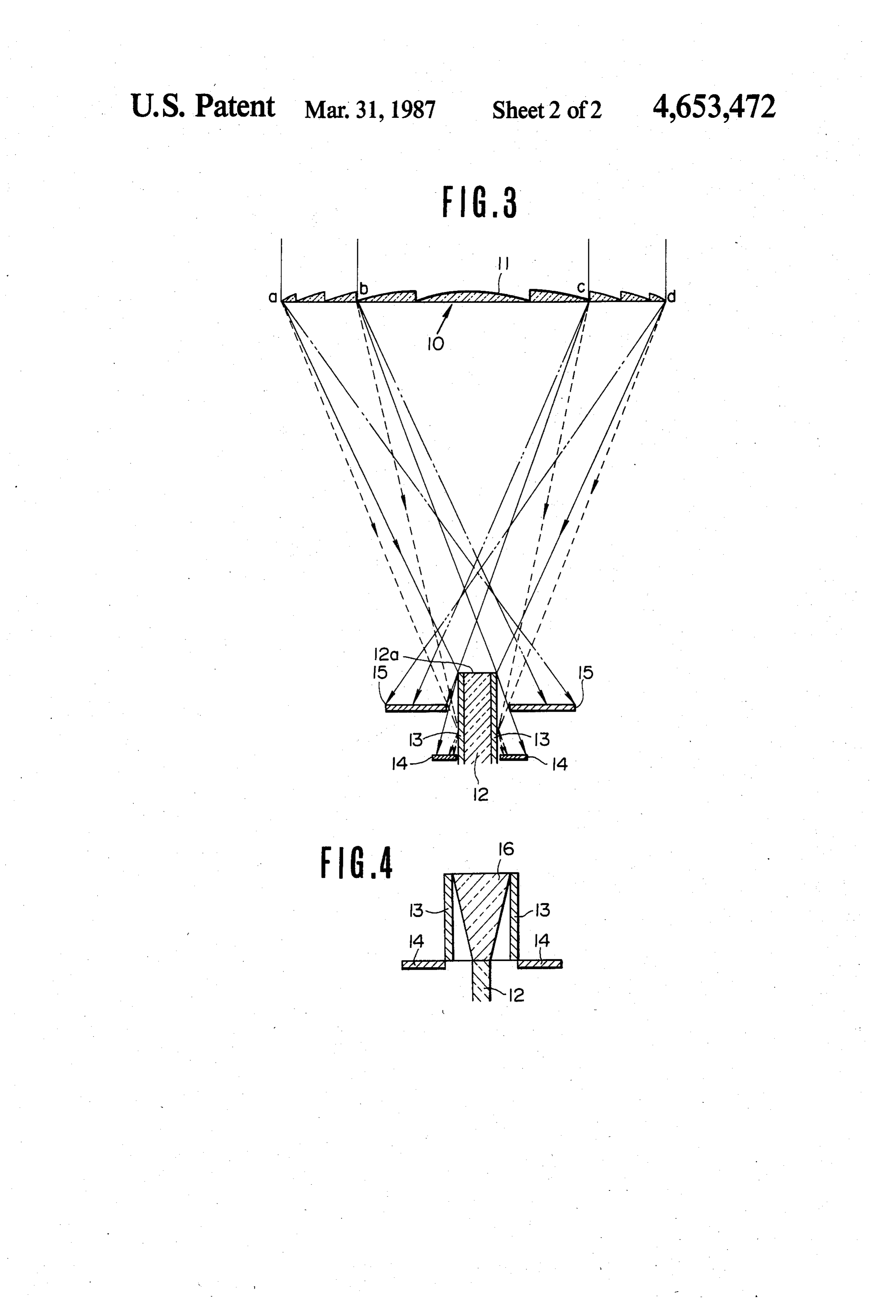
FIG. 3 is a construction view for explaining an em
SOLAR RAY ENERGY COLLECTING DEVICE bodiment of the solar ray energy collecting device ac cording to the present invention; and
BACKGROUND OF THE INVENTION FIG. 4 is a cross-sectional view for explaining an 5 other embodiment in which the focused solar rays are
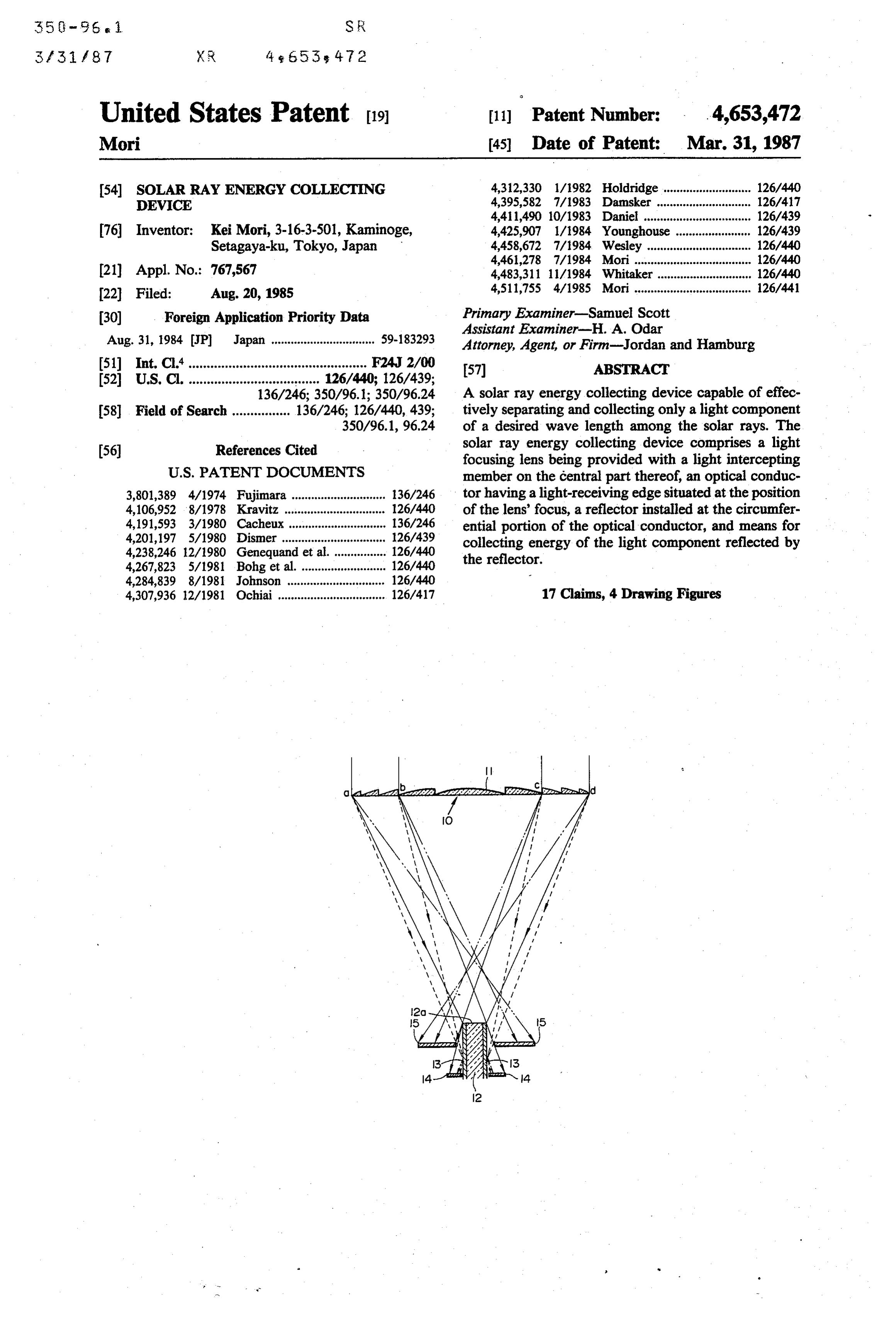
The present invention relates to a solar ray energy collecting device capable of effectively separating and guided into the optical conductor.
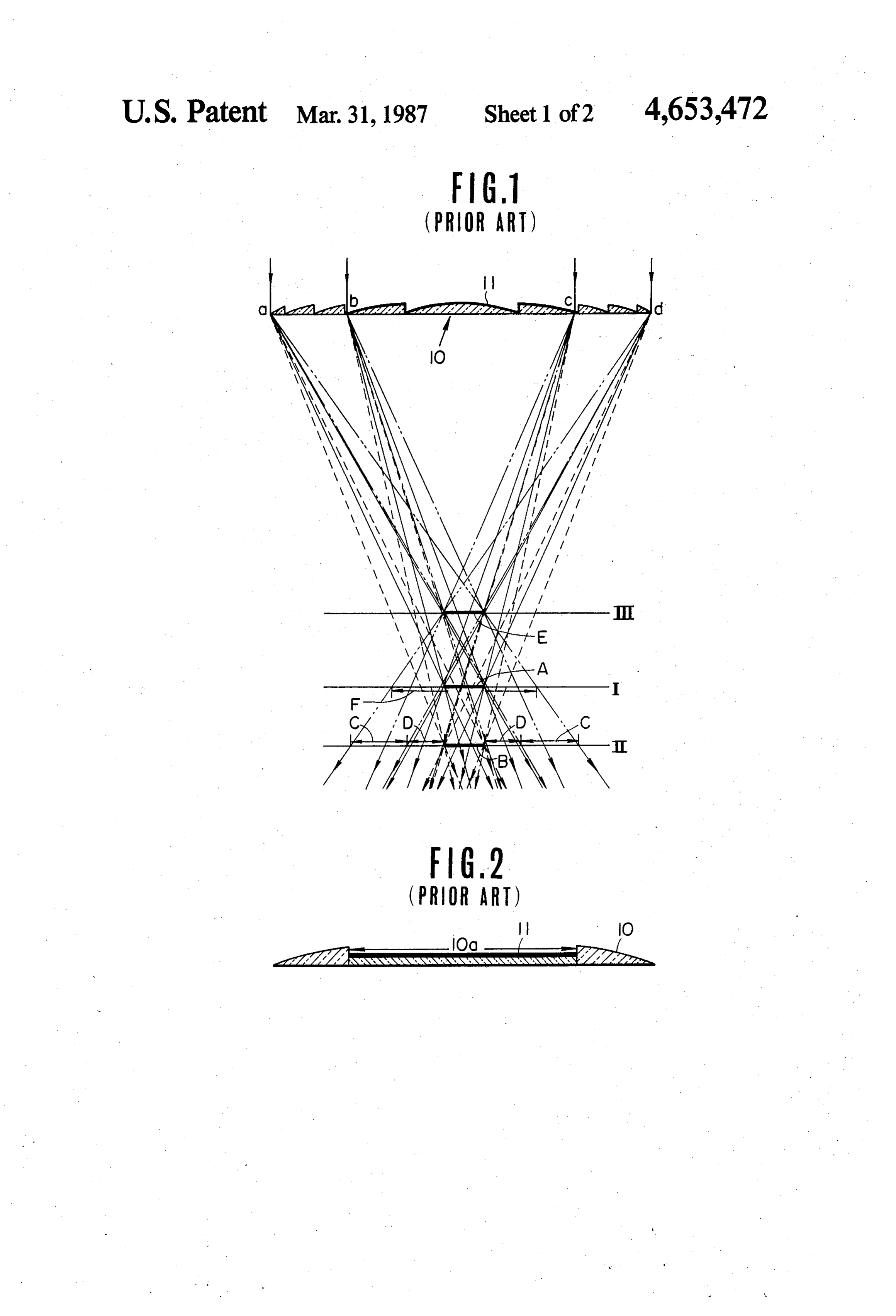
collecting only a light component of a desired wave DESCRIPTION OF THE PREFERRED length among the solar rays. w EMBODIMENTS The present applicant has previously proposed vari O FIG. 1 is a construction view for explaining a light ous ways to focus solar rays or artificial light rays by focusing lens which has been previously proposed by use of lenses or the like, to guide the same into an optical the present applicant. In FIG. 1, 10 is a Fresnel lens, and conductor, and thereby to transmit them onto an op 11 is a light intercepting membrane mounted on the tional desired place through the optical conductor for central portion of the Fresnel lens 11. The solar rays or use in illumination or for other like purposes. 15 the artificial light rays arrive directly at the points; a, b, However, in the case of employing the light energy c and d, of the lens 10 are focused, respectively, as transmitted through the optical conductor in such a shown in F.G. 1.
manner as mentioned above as a photo-synthesis light Moreover, in FIG. 1, the green light rays are shown source for nurturing chlorella or intensively cultivate by solid lines, the red light rays by dotted lines, and the the plants, a light source for breeding fish, a light source blue light rays by two-dots-and-dash lines, respectively. for promoting human health, and a light source utilized Therefore, at the portion A of the plane I in FIG. 1 for various other purposes, there are many cases in comparatively pure green light rays are concentrated, which only a desired light component fitted in the pur at the portion B of the plane II comparatively pure red pose of utilization needs to be selectively separated and 25 tivelyrays, light pure and at the portion E of the plane III compara blue light rays. Consequently, if each light employed among the light components contained in the receiving edge of the optical conductors is put at those light energies. portions; A, B and E, respectively, the light rays having However, although various techniques of cutting off only the desired light infrared rays, ultraviolet rays, or the like have already optical conductor. component can be guided into the been proposed up to now, a technique of taking out a 30 Moreover, on the plane II, the portion C is a blue light component of the specially designated wave light component area, and the portion D is a green light length among the white light rays has not yet been component area. It has been described, heretofore, that proposed at all. Furthermore, it was very difficult to the light-receiving edge of the optical conductor is obtain the infrared rays, the ultraviolet rays, or the like moved to the direction of the lens' optical axis so as to which contain no visible light rays' component or very 35 take out the light component of a desired wave length. small amount of component of those visible rays. However, the light component guided into the optical The present applicant has previously proposed in the conductor can be also changed in accordance with the other ways a light focusing lens capable of effectively diameter of the optical conductor. For instance, if the separating and taking out only a light component of a diameter of the optical conductor is equal to F on the desired wave length among the solar rays in consider- 40 plane I, the visible light rays containing the light con ation of the actual situation as mentioned above. ponents from red to blue are guided into the optical conductor.
SUMMARY OF THE INVENTION FIG. 2 is a cross-sectional view showing another The primary object of the present invention is to embodiment of the afore-mentioned light focusinglens. provide a solar ray energy collecting device capable of 45 In FIG. 2, a light focusing lens 10 has a central portion effectively separating and collecting only a light com 10a formed in a state of plane surface, and a light inter ponent of a desired wave length among the solar rays. cepting member 11 is mounted on the plane portion It is another object of the present invention to pro thereof. In relation to such a light focusing lens, the vide a solar ray energy collecting device in which a plane portion 10a can be formed at the same time when specially designated wave length component among the 50 the lens is formed, and thereby the dimension and loca solar rays energies can be utilized as the light energy tion of the light intercepting member can be determined precisely. And further, since the surface for mounting and the other wave length components can be utilized the light intercepting member thereon is plane, it will be as the thermal energy or the electric energy.
It is another object of the present invention to pro 55 Moreover, in the case ofintercepting very easy to form a light membrane 11.
vide a solar ray energy collecting device in which a light intercepting member, the lens is notreflector employing a heated as the at all.
desired wave length component can be separated from Consequently, there is less fear that the lens is not de the solar rays' components and taken out, and thereby it formed due to the heat. It is very preferable. In case that can be most effectively utilized in accordance with the there is no fear of being heated, the light intercepting wave length component. 60 member is not limited to the reflector. A light absorbing The above-mentioned features and other advantages material, a photoelectric converter, or the like can be of the present invention will be apparent from the fol used instead of the reflector. However, when the photo lowing detailed description which goes with the accom electric converter is used, the solar ray energy can be panying drawings. utilized much more effectively.
BRIEF DESCRIPTION OF THE DRAWINGS 65 FIG. 3 is a construction view for explaining an em bodiment of the solar ray energy collecting device ac
FIGS. 1 and 2 are views showing the light focusing cording to the present invention. In FIG. 3, 10 is a light lenses employed in the present invention, respectively. focusing lens as mentioned above, 11 a light intercept
Page 5
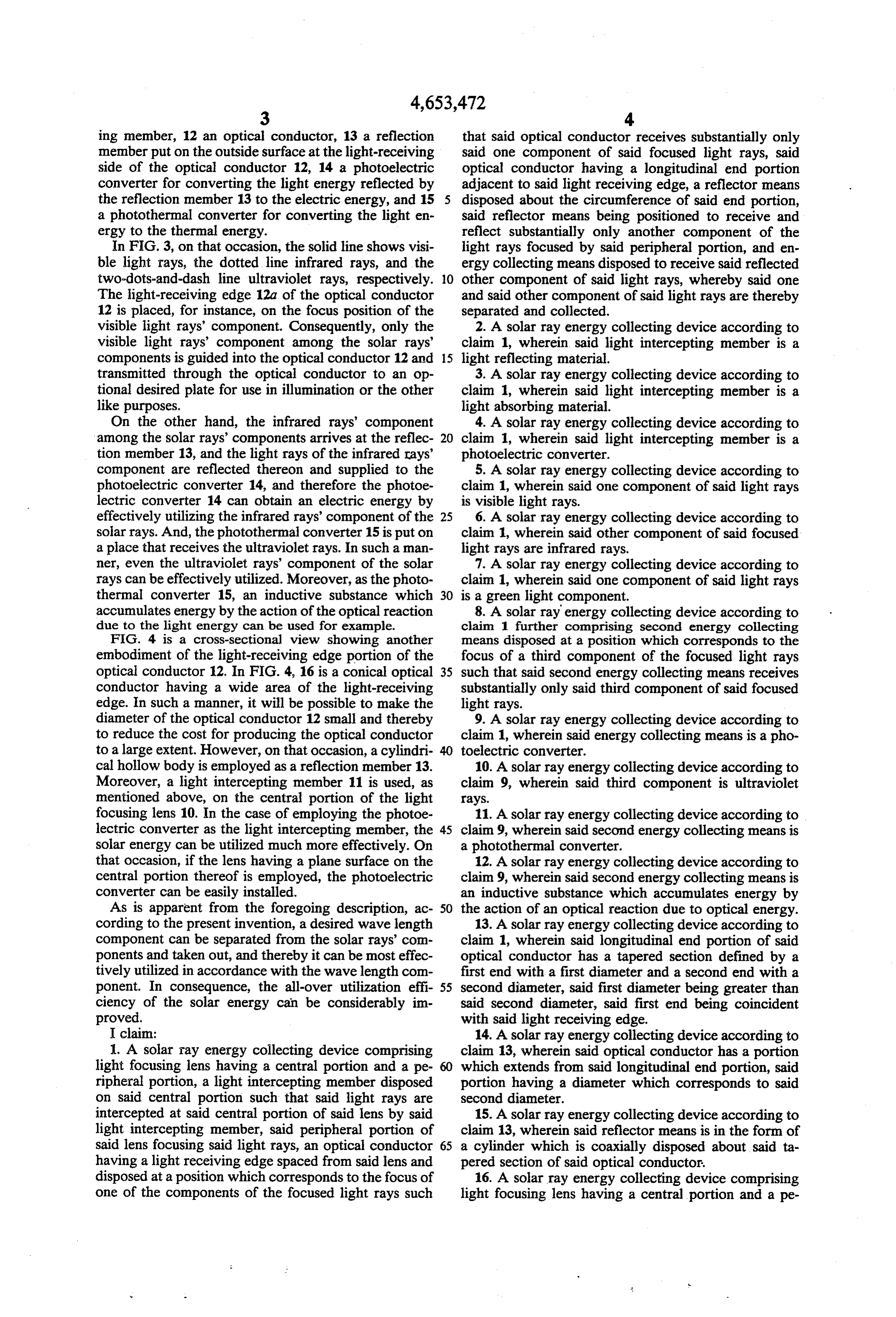
ing member, 12 an optical conductor, 13 a reflection that said optical conductor receives substantially only member put on the outside surface at the light-receiving said one component of said focused light rays, said side of the optical conductor 12, 14 a photoelectric optical conductor having a longitudinal end portion converter for converting the light energy reflected by adjacent to said light receiving edge, a reflector means the reflection member 13 to the electric energy, and 15 disposed about the circumference of said end portion, a photothermal converter for converting the light en said reflector means being positioned to receive and ergy to the thermal energy. reflect substantially only another component of the In FIG. 3, on that occasion, the solid line shows visi light rays focused by said peripheral portion, and en ble light rays, the dotted line infrared rays, and the ergy collecting means disposed to receive said reflected two-dots-and-dash line ultraviolet rays, respectively. 10 other component of said light rays, whereby said one The light-receiving edge 12a of the optical conductor and said other component of said light rays are thereby 12 is placed, for instance, on the focus position of the separated and collected.
visible light rays' component. Consequently, only the 2. A solar ray energy collecting device according to visible light rays' component among the solar rays' claim 1, wherein said light intercepting member is a components is guided into the optical conductor 12 and 15 light reflecting material.
transmitted through the optical conductor to an op 3. A solar ray energy collecting device according to tional desired plate for use in illumination or the other claim 1, wherein said light intercepting member is a like purposes. light absorbing material.
On the other hand, the infrared rays' component 4. A solar ray energy collecting device according to among the solar rays' components arrives at the reflec 20 claim 1, wherein said light intercepting member is a tion member 13, and the light rays of the infrared rays' photoelectric converter.
component are reflected thereon and supplied to the 5. A solar ray energy collecting device according to photoelectric converter 14, and therefore the photoe claim 1, wherein said one component of said light rays lectric converter 14 can obtain an electric energy by is visible light rays.
effectively utilizing the infrared rays' component of the 25 6. A solar ray energy collecting device according to solar rays. And, the photothermal converter 15 is put on claim 1, wherein said other component of said focused a place that receives the ultraviolet rays. In such a man light rays are infrared rays.
ner, even the ultraviolet rays' component of the solar 7. A solar ray energy collecting device according to rays can be effectively utilized. Moreover, as the photo claim 1, wherein said one component of said light rays thermal converter 15, an inductive substance which 30 is a green light component.
accumulates energy by the action of the optical reaction 8. A solar ray energy collecting device according to due to the light energy can be used for example. claim 1 further comprising second energy collecting FIG. 4 is a cross-sectional view showing another means disposed at a position which corresponds to the embodiment of the light-receiving edge portion of the focus of a third component of the focused light rays optical conductor 12. In FIG. 4, 16 is a conical optical 35 such that said second energy collecting means receives conductor having a wide area of the light-receiving substantially only said third component of said focused edge. In such a manner, it will be possible to make the light rays.
diameter of the optical conductor 12 small and thereby 9. A solar ray energy collecting device according to to reduce the cost for producing the optical conductor claim 1, wherein said energy collecting means is a pho to a large extent. However, on that occasion, a cylindri toelectric converter.
cal hollow body is employed as a reflection member 13. 10. A solar ray energy collecting device according to Moreover, a light intercepting member 11 is used, as claim 9, wherein said third component is ultraviolet mentioned above, on the central portion of the light rays.
focusing lens 10. In the case of employing the photoe 11. A solar ray energy collecting device according to lectric converter as the light intercepting member, the 45 claim 9, wherein said second energy collecting means is solar energy can be utilized much more effectively. On a photothermal converter.
that occasion, if the lens having a plane surface on the 12. A solar ray energy collecting device according to central portion thereof is employed, the photoelectric claim 9, wherein said second energy collecting means is converter can be easily installed. an inductive substance which accumulates energy by As is apparent from the foregoing description, ac 50 the action of an optical reaction due to optical energy. cording to the present invention, a desired wave length 13. A solar ray energy collecting device according to component can be separated from the solar rays' com claim 1, wherein said longitudinal end portion of said ponents and taken out, and thereby it can be most effec optical conductor has a tapered section defined by a tively utilized in accordance with the wave length com first end with a first diameter and a second end with a ponent. In consequence, the all-over utilization effi 55 second diameter, said first diameter being greater than ciency of the solar energy can be considerably im said second diameter, said first end being coincident proved. with said light receiving edge. I claim: 14. A solar ray energy collecting device according to 1. A solar ray energy collecting device comprising claim 13, wherein said optical conductor has a portion light focusing lens having a central portion and a pe which extends from said longitudinal end portion, said ripheral portion, a light intercepting member disposed portion having a diameter which corresponds to said on said central portion such that said light rays are second diameter.
intercepted at said central portion of said lens by said 15. A solar ray energy collecting device according to light intercepting member, said peripheral portion of claim 13, wherein said reflector means is in the form of said lens focusing said light rays, an optical conductor 65 a cylinder which is coaxially disposed about said ta having a light receiving edge spaced from said lens and pered section of said optical conductor. disposed at a position which corresponds to the focus of 16. A solar ray energy collecting device comprising one of the components of the focused light rays such light focusing lens having a central portion and a pe
Page 6
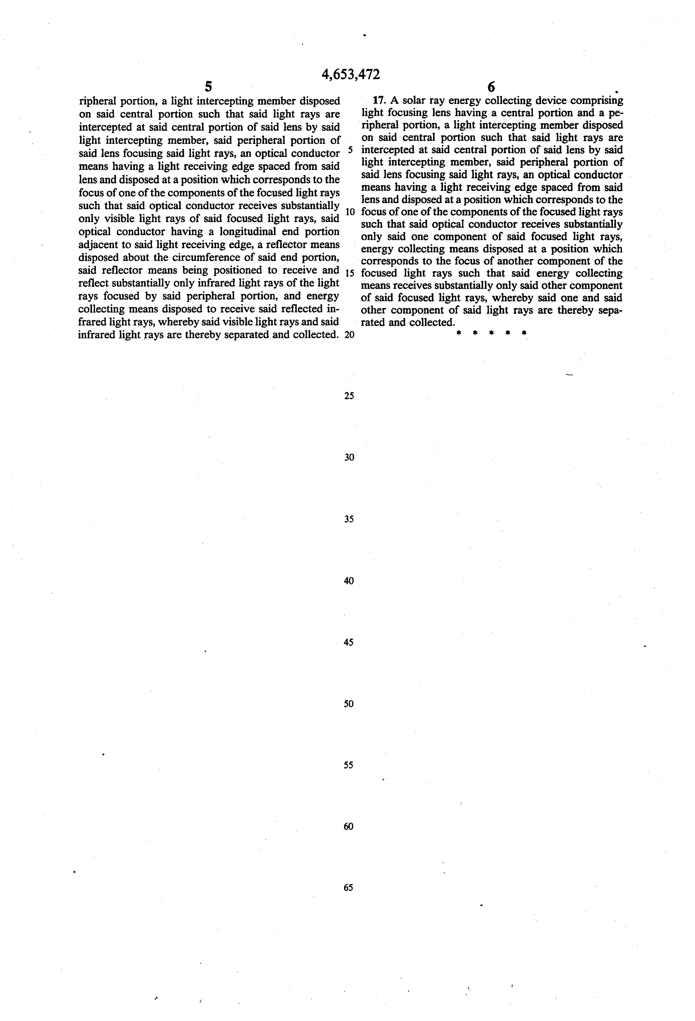
5 6 Y. ripheral portion, a light intercepting member disposed 17. A solar ray energy collecting device comprising on said central portion such that said light rays are light focusing lens having a central portion and a pe intercepted at said central portion of said lens by said ripheral portion, a light intercepting member disposed light intercepting member, said peripheral portion of on said central portion such that said light rays are said lens focusing said light rays, an optical conductor 5 intercepted at said central portion of said lens by said means having a light receiving edge spaced from said light intercepting member, said peripheral portion of lens and disposed at a position which corresponds to the said lens focusing said light rays, an optical conductor focus of one of the components of the focused light rays lens andhaving means a light receiving edge spaced from said such that said optical conductor receives substantially O focus of one of theatcomponents disposed a position which corresponds to the only visible light rays of said focused light rays, said such that said optical conductorof receives the focused light rays optical conductor having a longitudinal end portion only said one component of said focusedsubstantially light rays, adjacent to said light receiving edge, a reflector means energy collecting means disposed at a position which disposed about the circumference of said end portion, corresponds to the focus of another component of the said reflector means being positioned to receive and 15 focused light rays such that said energy collecting reflect substantially only infrared light rays of the light means receives substantially only said other component rays focused by said peripheral portion, and energy of said focused light rays, whereby said one and said collecting means disposed to receive said reflected in other component of said light rays are thereby sepa frared light rays, whereby said visible light rays and said rated and collected.
infrared light rays are thereby separated and collected. 20 s
Provenance
- Collection
- Cited prior art
- Original PDF
- patentimages.storage.googleapis.com →
- Filed
- 1985-08-20
- Pages
- 6
- Method
- pdftotext (the PDF's own text layer) + pdftoppm 300dpi page scans
- Source
- Google Patents bibliographic record
- Granted
- 1987-03-31
- Inventors
- Kei Mori
- Transcribed from
- patentimages.storage.googleapis.com →