patent · US4333447
Solar receiver tube support
8 June 1982
Page 1 — bibliographic record
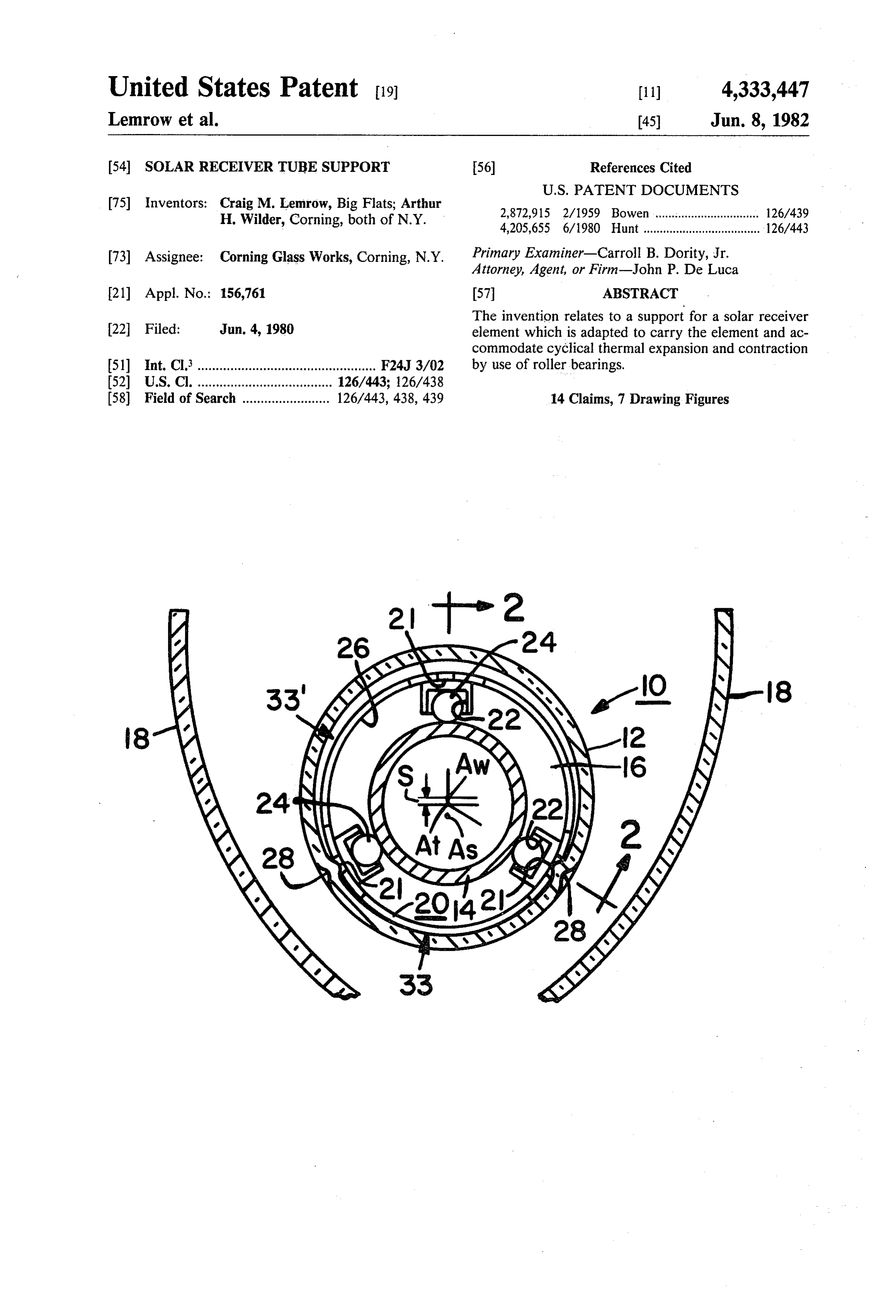
United States Patent (19) 11 4,333,447 Lemrow et al. 45) Jun. 8, 1982 54 SOLAR RECEIVERTUBE SUPPORT 56) References Cited
(75) Inventors: Craig M. Lemrow, Big Flats; Arthur 2,872,915 2/1959 Bowen ................................ 126/439 H. Wilder, Corning, both of N.Y. 4,205,655 6/1980 Hunt .................................... 126/443 (73) Assignee: Corning Glass Works, Corning, N.Y. Primary Examiner-Carroll B. Dority, Jr. Attorney, Agent, or Firm-John P. De Luca 21 Appl. No.: 156,761 57 ABSTRACT The invention relates to a support for a solar receiver 22 Filed: Jun. 4, 1980 element which is adapted to carry the element and ac commodate cyclical thermal expansion and contraction (51) Int. Cl. ................................................. F24J 3/02 by use of roller bearings.
(52) U.S.C. ..................................... 126/443; 126/438 (58) Field of Search ........................ 126/443, 438,439 14 Claims, 7 Drawing Figures
Page 2
Drawing sheet — no readable text.
Page 3
Drawing sheet — no readable text.
Page 4
element as it expands and contracts during thermal
SOLAR RECEIVERTUBE SUPPORT cycles. A frame member is located between the surfaces and includes a retainer for associately accommodating
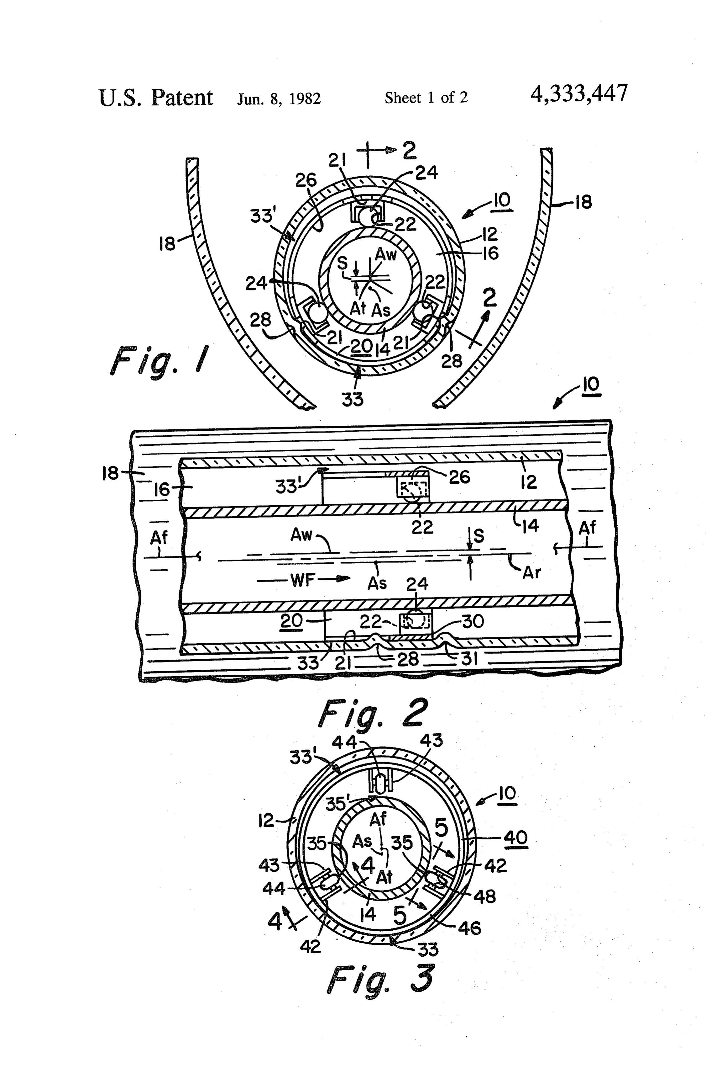
BACKGROUND OF THE INVENTION one each of the roiler bearings therein and securing In designing evacuated solar receivers for parabolic 5 each to a limited path of rotation relative to the window trough concentrators, it is desirable to make the re and receiver element during each thermal cycle. ceiver or absorber and the evacuated envelope sur DESCRIPTION OF THE DRAWINGS rounding same as long as possible such that connection and end losses are minimized. By reducing the number O FIG. 1 is an end section in elevation of a receiver tube of ends, materials requirements are reduced and fabrica incorporating the support member of the present inven tion is simplified. Further, manifolding is simplified and tion. .
the significant thermal losses associated therewith can FIG. 2 is a fragmented side section in elevation taken be substantially reduced. along line 2-2 of FIG. 1.
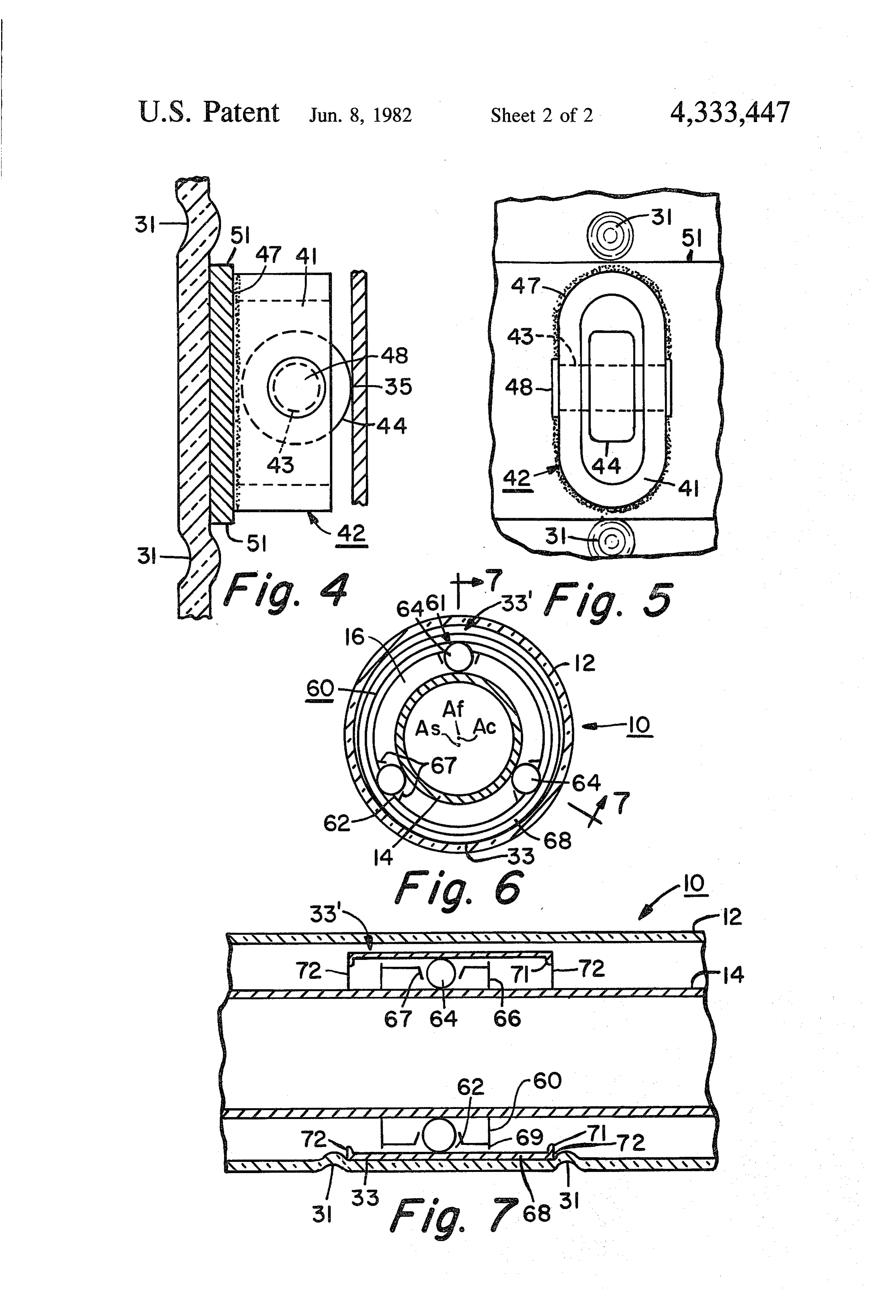
It now appears feasible to manufacture receivers in FIG. 3 is an end section of another embodiment of the excess of 20 feet in length. A metal receiver or absorber 15 present invention incorporating pinned rollers therein. tube this length would, by its own weight and that of FIGS. 4 and 5 are enlarged side and top elevations, of the heat transfer fluid contained therein, deflect much the pinned rollers illustrated in FIG. 3, respectively more than would be tolerable to maintain the absorber taken along lines 4-4 and 5-5 of FIG. 3. . . within the focal line of a parabolic trough. For example, FIG. 6 is an end view in section of yet another em a receiver tube 24 feet long consisting of a steel tube 1." 'bodiment of the present invention. O.D. by 0.1' wall thickness supported at its ends would FIG. 7 is a side section in elevation taken along line deflect by its own weight about 4' near its center. A 7-7 of FIG. 6.
glass tube or envelope 2" O.D. by 0.1' wall thickness would deflect about 1'. Even if such bending could be DESCRIPTION OF THE PREFERRED tolerated from a stress point of view, the fact is the 25 EMBODIMENT .. . .
absorber or receiver portion of the solar collector FIGS. 1 and 2 show an embodiment of the present would be in contact with the glass envelope and would invention in the environment of an evacuated tubular thus create intolerable thermal losses which the evacu ated envelope is designed to reduce. The prior art a tubular glass,or solar collector receiver 10. The collector 10 includes envelope or solar window 12 surround shows various receiver tube supports. See for example 30 ing a metal absorber or receiver tube 14 located axially FIGS. 8 and 22 in U.S. Pat. No. 4,133,298. The disad therealong. The window 12 and receiver 14 each have vantages of such a system will become readily apparent respective central axes Aw and Ar. While in the collec hereinafter from the present disclosure.
In addition to the deflection problem mentioned tor 10 shown, the axes Aw and Ar may be designed coaxially, one appears spaced from the other for reasons above, the operating temperatures contemplated e.g. 35. hereinafter explained. The receiver tube 14 is separated 650 F., means that, a steel receiver tube or absorber from the would expand linearily about 1' through an extreme 16. A working fluidenvelope or window 12 by an evacuated space excursion from cold to hot in the thermal cycle. The absorber tube 14 to conduct WF may be passed through the support for the absorber therefor must be able to ac sensible heat therefrom as a commodate the movement between the absorber and 40 result of insolation of the absorber 14, 3. the glass envelope. The glass also expands but to a much In certain kinds of solar collectors, the insolation may lesser degree since the thermal expansion is much lower be concentrated by the use of a reflector 18 in the form and the temperature for the glass would not reach the of a parabolic mirror having a linear focal line Af. temperature of the absorber (probably no more than While the geometry of such reflectors is important to 250 F). 45 the art of concentrating solar collectors, for the purpose The support for an extremely long receiver tube of the explanation herein, it will be assumed that the axis therefore must be substantial to provide the support Af of the reflector 18 is located more or less colinearily necessary considering the greater weight and amount of with the window axis Aw and closely-with the receiver deflection and must also be capable of accommodating tube axis Ar. Thus, it should be understood that, if the the linear expansion of the receiver tube while at the 50 absorber 14 moves substantially away from the focal same time protecting the inside surface of the glass line Afthe concentrating power of the reflector 18 will envelope or housing from abrasion over a contemplated be reduced and hence the efficiency of the collector 10 useful life of twenty years. will be diminished.
A support 20 is located in the evacuated space 1
SUMMARY OF THE INVENTION 55 between the envelope 12 and the absorber 14. The sup In a housing for a solar energy collector having a port 20 is adapted to space the absorber or receiver tube solar window portion and a thermally cyclical solar 14 from the envelope 12 and maintain the absorber axis energy receiver element located therewithin, a support Ar closely along the focal line Afas much as possible. element has been provided adapted to locate the re In the embodiment shown the support 20 includes a ceiver in spaced relation with respect to the window 60 frame member 26, a plurality of retainer cavities 22 and and to accommodate linear expansion and contraction associated ball bearings 24 located therein. The frame of the receiver element relative to the window due to 26 may be an annular ring which loosely fits about the thermal cycling thereof. The support includes a bearing absorber 14 and within the inside dimension of the enve adapted to engage opposed surfaces of the receiver lope 12. Frame 26 has a plurality of linear slots 21 for element and the window and includes a plurality of 65 accommodating one or more appropriately located wall roller bearings being selectively located between the dimples 28 in window. 12. Each slot 21 and dimple 28 opposed surfaces for spacing and supporting one against cooperate to prevent axial movement of the frame 26 (to the other and being free to rollably carry the receiver the left in FIG. 2) and circumferential motion (rotation
Page 5
ally in FIG. 1). One or more additional wall dimples 31 on bearing 48 as illustrated. The oblong members 41 engage a margin 30 of frame 26 to prevent axial motion may be welded to the frame 46 at weldment 47. It is away from dimple 28 (to the right in FIG. 2). As the possible also to provide a stamping for accomplishing absorber 14 expands and contracts under the influence the formation of the retainer ears 42 as an alternative. of the solar radiation or insolation the lower two of ball Dimples 31 in the wall of envelope 12 restrain axial bearings 24 provide support for and accommodate the movement of frame 46 at opposed margins 51 thereof. linear expansion and contraction of the absorber 14. The In the embodiments illustrated in FIGS. 6 and 7 the frequent thermal cycling of the absorber 14 creates in collector 10 has a support 60 in the form of a roller the support 20 a tendency to creep axially and circum bearing and race set. Roller bearings 64 are accommo ferentially of the tube 12. Since the frame 26 is retained 10 dated in a race 66 which is similar to the frame members in position as shown by dimples 28 and 31, and the ball previously discussed. The roller bearings 64 carry the bearings 24 roll against the metal absorber tube 14, the absorber 14 and space it from the glass of the solar envelope 12 is protected from glass to metal abrasion of window or envelope 12. In order to safeguard the glass its inside surface through uncounted thermal cycles from abrasion by roller bearings 64 a protective shield over its useful life. 15 68 is provided to both retain the roller bearings 64 in The frame 26 is purposely designed to be smaller in place and to protect the glass. Each of the roller bear diameter than that of the window 12 to facilitate assem ings 64 are accommodated in apertures 62 of the race bly and to minimize contact area therebetween (see 66. Dimpled annular margins 67 of apertures 62 stabily arrow 33). Remaining portions of frame 26 are thus locate the roller bearings 64 radially in the circumferen spaced away from the glass window 12 (see arrow 33). 20 tial positions shown.
This limited contact reduces the cross-sectional area The race 66 includes depending ears 69 located at the available for thermal leakage. Since it is assumed that opposed margins thereof and the shield 68 includes absorber 14 would sag but for support 20 and because depending ears 71 directed in opposition to the ears 69. the latter may be designed to be off axis of the envelope In FIG. 7 especially it can be seen that the respective 12, the receiver tube 14 and envelope 12 have closely 25 ears 69 and 71 overlap radially. In addition the shield 68 spaced but non-colinear axes. (See dimensions in FIG. is about twice as wide as the race 66 and as the absorber 1). As long as the dimensions is small, the axial discrep 14 expands and contracts the race 66 and roller bearings ancy is not thought to be important in terms of effi 64 move linearily or axially of the collector 10. In the ciency. Similarly an axis for the support As may be embodiment shown the race 66 and roller bearings 64 located off center as shown. For purposes of the disclo 30 will move linearily about one-half the amount that the sure the support 20 can be said to be substantially con absorber 14 moves during each thermal cycle. As the centric with the envelope 12 and/or absorber tube 14. race 66 moves back and forth the ears 69 of the race 66 In another embodiment of the present invention illus may engage the ears 71 of the shield 68 and thus prevent trated in FIG. 3, the solar collector 10 incorporates a the race 66 from creeping therebeyond. The dimples 31 support 40. (Reflector 18 shown in FIG. 1 is omitted in 35 are located in the wall of the glass envelope 12 at op order to simplify the drawing and other reference nu posed margins 72 of the shield 68 near the ears 71 to merals are retained as appropriate.) The support 40 retain the entire assembly of the support 60 axially in includes a frame member 46, a plurality of apertured place.
retainer ears 42, rollers 44 and through shafts or bear As in the earlier embodiments described herein the ings 48. Rollers 44 are carried by an associated one of 40 uppermost of the roller bearings 64 carries essentially the bearings 48 which have free ends 49 journaled or none of the weight of the absorber tube 14. In this em sleevably located in opposed axial apertures 43 of the bodiment as above the support 60 has a diameter some retainer ears 42. The rollers 44 bear against the absorber what smaller than that of the window 12 and thus when 14 and maintain its spacing from the window 12 as well the collector 10 is in the horizontal position shown, the as allow for linear expansion and contraction of the 45 shield 68 rests on the lower inside surface of the win absorber 14 along its axis At. dow 12 at 33 and leaves spaces near the upper portion The support 40 is constructed so that only two of the 33' as illustrated. This loose fitting arrangement not three rollers 44 need actually contact the absorber 14 at only reduces thermal cross section as mentioned above any one time. Note for example the space between the but allows for wall thickness and diameter variation of uppermost roller 44 in the drawing of FIG. 3 and the 50 the components.
absorber 14 (see arrow 35). The lower two rollers 44 The material forming the supports illustrated in the contact and bear absorber 14 against its weight in the various embodiments herein may be fabricated from downward direction at contact points 35. As above highly reflective material in both the visible and infra described in the embodiment of FIGS. 1 and 2, the red range thus avoiding excessive localized heating of frame 46 is designed to have minimal contact with the 55 the glass envelope as the support comes in contact envelope 12 at lower portion 33 and be spaced away therewith. Further some of the bearings might be fabri above at 33". The fact that there are three rollers 44 cated from ceramic material in order to reduce the mounted in the apertured retainer ears 42 as illustrated, thermal conductivity of the path between the absorber simplifies the shipping process so that the solar receiv 14 and the window 12.
ers 10 can be oriented in any manner during shipping 60 Referring to FIGS. 1 and 2, it should be understood and installation or operation, however, for purposes of that slots 21 in frame 26 which are engaged by dimples function the two lower rollers in the embodiment illus 28 to prevent circumferential creep may be provided as trated shown bear or carry the absorber tube 14 and desired in the embodiments of the remaining Figures. accommodate its linear expansion. It should be realized that while the embodiments FIGS. 4 and 5 show the details of the retainer ears 42 65 described above are preferred the invention can be and roller bearings 44 in enlarged views. Each of the adapted for other types of collectors, specifically flat former includes an oblong annular member 41 with the plates and evacuated tubular collectors utilizing such apertures 43 formed therein. Each roller 44 is mounted structures, if the absorber in such a device needs sup
Page 6
port. In such a case, the frame would be modified to the concentric member for receiving therein at least an accommodate the shape and configuration of the ab associated one of the roller bearings. sorber. 7. An evacuated solar tubular collector wherein a We claim: tubular receiver element is axially surrounded and 1. In a solar energy collector having a solar window 5 sealed within a tubular glass envelope or solar window, portion and a thermally cyclical solar energy receiver a support for the receiver element comprising: a bearing element located therewithin, a support for the receiver adapted to accommodate linear expansion and contrac element adapted to locate same in spaced relation with tion of the receiver element relative to the window due respect to the window and to accommodate linear ex to thermal cycles thereof, said bearing adapted to en pansion and contraction of the receiver element relative O gage opposed substantially concentric surfaces of the to the window due to thermal cycles thereof, the sup receiver element and window including an annular port comprising; a bearing adapted to engage opposed frame member adapted to be fitted about the receiver surfaces of the receiver element and the window includ element and loosely within the window, said frame ing a plurality of roller bearings being selectively lo having retainer apertures circumferentially located cated between the opposed surfaces of said window and 15 therein and a roller bearing located within each of the said receiver for spacing one from the other and being apertures adapted to closely engage the receiver ele free to rollably carry the receiver element as it expands ment to space it from the window and rollably accom and contracts during thermal cycles, and a frame mem modate axial movement thereof, means associated with ber located between said opposed surfaces of said win the window adapted to engage the frame and axially dow and said receiver including retainer means for 20 locate same within the envelope to inhibit axial creep of associatively accommodating one each of the roller the bearing during thermal cycling of the receiver. bearings therein and securing each to a limited path of 8. The support of claim 7 wherein the frame includes rotation relative to the window and the receiver ele ment during each thermal cycle. circumferentially located retainer ears radially depend 2. The support of claim 1 further including means therein 25 ing from the frame having the retainer apertures located associated with at least one of said opposed surfaces for as a pair of opposed openings axially parallel engaging with and relatively fixedly locating the frame with the receiver; and each of the roller bearings in relative thereto in a direction of expansion and contrac cludes a roller wheel and shaft axially mounted thereto, tion of the receiver. having opposed free ends sleeved within the opposed 3. The support of claim 1 wherein the frame includes 30 openings of the ears.
9. The support of claim 7 wherein the frame is fabri a pair of concentric members having lateral margins, cated from a material having a relatively high infrared each member engaging one of the respective surfaces of and visible reflectance.
the housing and the receiver element, and the retainer means includes a pair of ears, one each depending from are fabricated fromofthermally 10. The support claim 7 wherein the roller bearings insulated material.
each margin extending towards the other by an amount 35 such that a distal portion of one ear overlaps a similar 11. The support of claim 7 wherein the frame is portion of an opposed member both radially and trans adapted to rest against the window and space it from the versely, and said roller bearing being located between receiver element and provide a minimum area of the overlapping ears. contact with the former for reducing thermal leakage 4. The support of claim 1 wherein the frame includes 40 from the receiver to the window.
a first member substantially concentric with one of the 12. The support of claim 7 wherein the frame in window and the receiver element having lateral mar cludes: a pair of substantially concentric annular rings, gins, the frame engaging one of said opposed surfaces an inner one having apertures to accommodate the and the retainer means includes, depending ears extend roller bearings therein and outer one adapted to sur ing from margins thereof towards the opposite surface a 45 round the rollers radially and shield the window from sufficient distance to secure the roller laterally therein contact therewith.
over a portion of its diameter. 13. The support of claim 7 wherein the means for 5. The support of claim 4 wherein the frame includes locating the frame axially of the window include dim a second substantially concentric member opposed to ples formed interiorally of the window and being the first mentioned one engaging the opposite surface 50 spaced to engage opposed axial margins of the frame from the first for bearing diametrically against the roller and retain it therebetween.
bearing. 14. The support of claim 13 wherein the frame has 6. The support of claim 1 wherein the frame includes marginal slots for engaging the dimples for preventing a member substantially concentric with one of the sur circumferential creep thereof. k sk faces and the retainer means is formed of apertures in 55
Provenance
- Collection
- Cited prior art
- Original PDF
- patentimages.storage.googleapis.com →
- Filed
- 1980-06-04
- Pages
- 6
- Method
- pdftotext (the PDF's own text layer) + pdftoppm 300dpi page scans
- Source
- Google Patents bibliographic record
- Granted
- 1982-06-08
- Inventors
- Craig M. Lemrow; Arthur H. Wilder; Corning Glass Works
- Transcribed from
- patentimages.storage.googleapis.com →