patent · US4588151
Solar ray collector for spacecraft
13 May 1986
Page 1 — bibliographic record
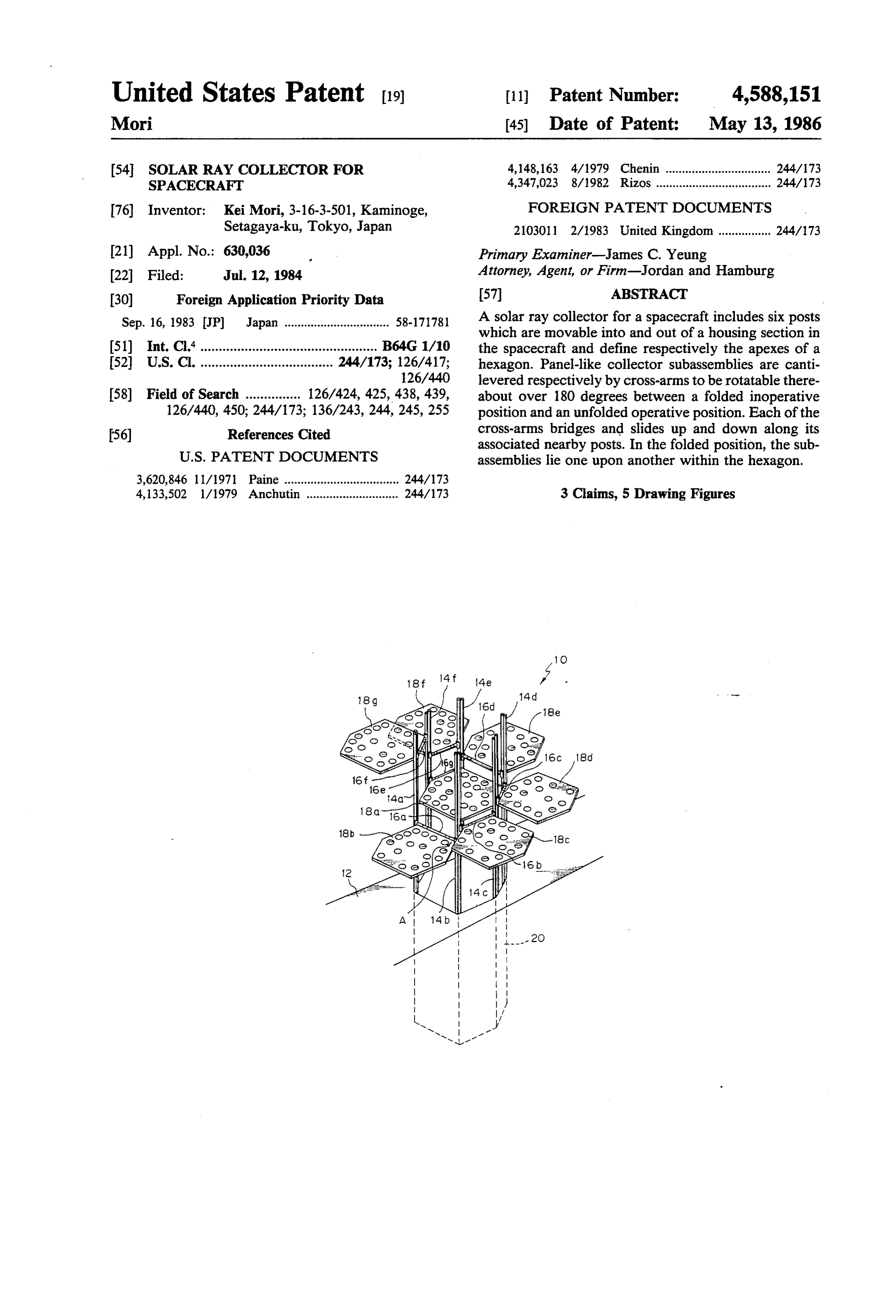
United States Patent (19) 11 Patent Number: 4,588,151 Mori 45) Date of Patent: May 13, 1986 54 SOLAR RAY COLLECTOR FOR 4,148,163 4/1979 Chenin ................................ 244/173 SPACECRAFT 4,347,023 8/1982 Rizos ................................... 244/173 76 Inventor: Kei Mori, 3-16-3-501, Kaminoge, FOREIGN PATENT DOCUMENTS Setagaya-ku, Tokyo, Japan 2103011 2/1983 United Kingdom ................ 244/173 21) Appl. No.: 630,036 s Primary Examiner-James C. Yeung 22 Filed: Jul. 12, 1984 Attorney, Agent, or Firm-Jordan and Hamburg 30 Foreign Application Priority Data 57 ABSTRACT Sep. 16, 1983 JP Japan ................................ 58-171781 A solar ray collector for a spacecraft includes six posts which are movable into and out of a housing section in 51) Int. Cl." ................................................ B64G 1/10 the spacecraft and define respectively the apexes of a 52 U.S. C. .................................... 244/173; 126/417; hexagon. Panel-like collector subassemblies are canti 126/440 levered respectively by cross-arms to be rotatable there 58) Field of Search ............... 126/424, 425,438,439, about over 180 degrees between a folded inoperative 126/440, 450; 244/173; 136/243, 244, 245, 255 position and an unfolded operative position. Each of the 56) References Cited cross-arms bridges and slides up and down along its associated nearby posts. In the folded position, the sub
3,620,846 11/1971 Paine ................................... 244/173 4,133,502 1/1979 Anchutin ............................ 244/173 3 Claims, 5 Drawing Figures
Page 2
Drawing sheet — no readable text.
Page 3
Drawing sheet — no readable text.
Page 4
Drawing sheet — no readable text.
Page 5
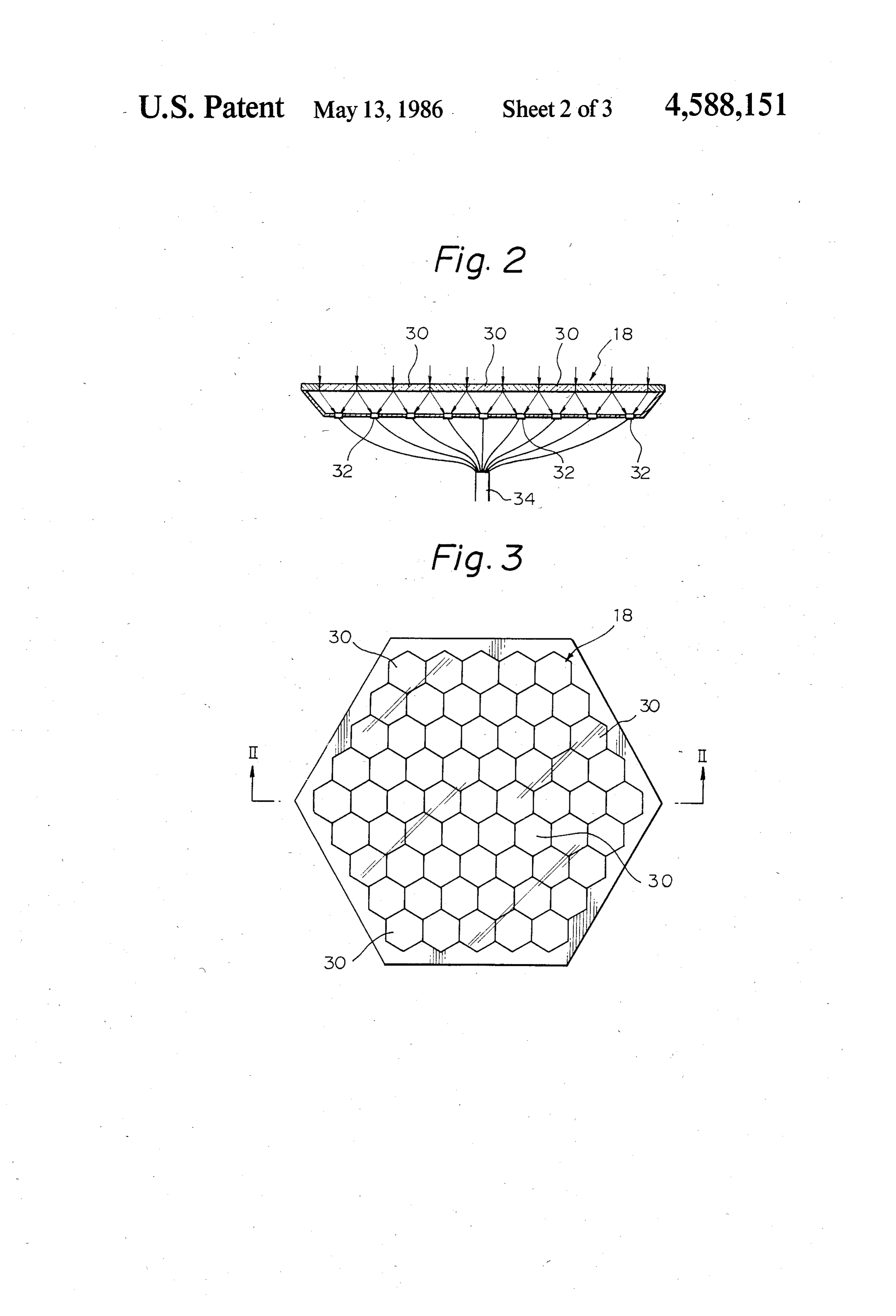
FIG. 2 is a sectional side elevation (along line II-II
SOLAR RAY COLLECTOR FOR SPACECRAFT of FIG. 3) of a collector subassembly desirably applica ble to the present invention;
BACKGROUND OF THE INVENTION FIG. 3 is a plan view of the collector subassembly
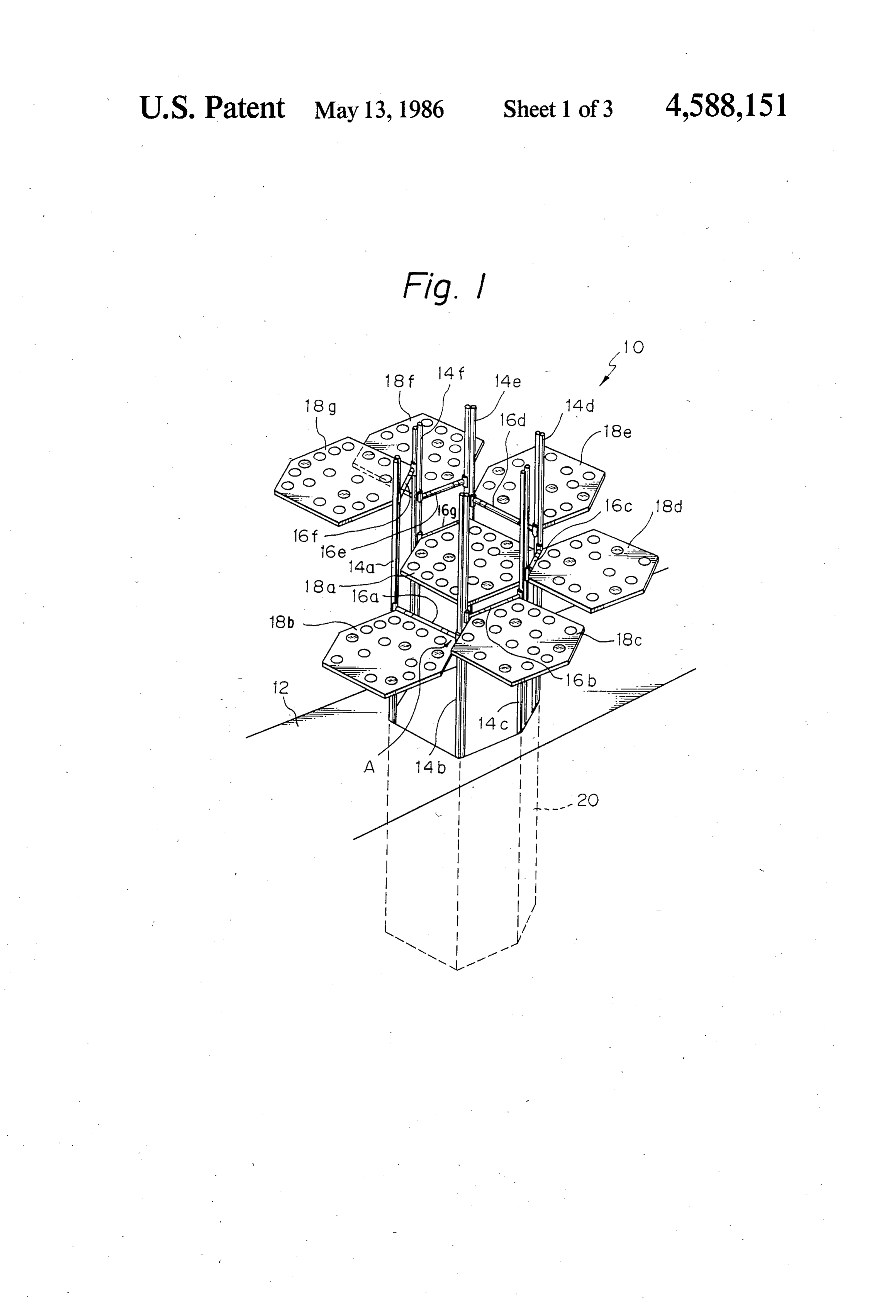
The present invention relates to a solar ray collector FIG. 4 is a section showing an encircled portion A of and, more particularly, to a solar ray collector which is FIG. 1 in detail; and suitable for use with a spacecraft. FIG. 5 is a side elevation of the solar ray collector of There has been proposed in various forms a system in FIG. 1 which is in a folded inoperative position. which lenses or the like converge solar radiation into 10 DESCRIPTION OF THE PREFERRED light conducting members so that the solar radiation is EMBODIMENT transmitted to a desired location to serve as a light source such as for lighting or culture of chlorella. While the solar ray collector for a spacecraft of the In parallel with the development in space engineer present invention is susceptible of numerous physical ing, the expected duration of stay of astronauts and 15 embodiments, depending upon the environment and others in the space is growing longer and longer. One of requirements of use, a substantial number of the herein critical conditions for such a long stay in the space is the shown and described embodiment have been made, supply of oxygen and food in a spacecraft. While such tested and used, and all have performed in an eminently may be implemented by loading a spacecraft with oxy satisfactory manner.
gen cylinders and food before launching it, the ever 20 lector Referring to FIG. 1 of the drawings, a solar ray col increasing number of crews and time of their stay in the unfolded embodying the present invention is shown in its space will soon come to require oxygen cylinders and operative position. The collector, generally 10, is mounted on an outer wall 12 of a spacecraft and fresh food more than a spacecraft can carry. It is there includes fore required to furnish a space craft with some imple six posts 14a, 14b, 14c, 14d, 14e and 14f which mentation for the self-supply of oxygen and fresh food 25 protrude from the outer wall 12. As shown, the posts within the spacecraft. The most effective energy source arms 16a, 16b,located 14a-14fare at the apexes of a hexagon. Cross 16c, 1.6d, 16e, 16f and 16g are individually available in the space is, as a matter of course, solar movable up and down along and between the nearby radiation. The prior art solar collection and delivery system previously described, although effective on the 30 posts 14a-14f Collector subassemblies 18a, 18b, 18c, 18d, 18e, 18f and 18g are mounted respectively on the earth, are not suitable for use in the space. cross-arms 16a-16g to be rotatable thereabout between SUMMARY OF THE INVENTION the illustrated unfolded operative position and folded inoperative position, which will be described. The ref.
It is therefore an object of the present invention to erence numeral 20 designates a housing section defined provide a solar ray collector which is suitable for use in 35 inside the spacecraft in order to accommodate the solar the space. collector 10. If desired, the housing section 20 may be It is another object of the present invention to pro positioned outside the spacecraft. -- - - - vide a generally improved solar ray collector. Details of each collector subassembly 18 are shown in A solar ray collector for use with a spacecraft of the FIGS. 2 and 3. Each collector subassembly 18 has a present invention comprises posts extending respec 40 light receiving surface which is substantially identical in tively from apexes of a hexagon which is defined on an shape with the hexagon defined by the posts 14a-14f. In outer periphery of the spacecraft, cross-arms each this particular embodiment, the collector subassembly bridging the nearby posts and slidable up and down 18 comprises sixty-one lenses 30 each having a diameter along the nearby posts, and collector subassemblies of about 4 centimeters. It should be noted, however, the each having a light receiving surface which is substan 45 number of lenses 30 shown and described is only illus tially identical in shape with the hexagon, each of the trative and even several thousands or more lenses may collector subassemblies being rotatably mounted on a be used. Optical fibers 32 are arranged such that the light receiving end of each is accurately aligned with respective one of said cross-arms at one side thereof. the focal point of a respective one of the lenses 30. In In a preferred embodiment, the collector subassem 50 this blies, when in operation, are unfolded to the outside of into construction, the associated solar rays converged by the lenses optical fibers 32 are transmitted to said hexagon such that the light receiving surfaces thereof are substantially perpendicular to the posts and, desired locations by the optical fibers 32 or, as shown in FIG. 2, by way of a fiber optic cable 34 to which the when out of use, folded to the inside of the hexagon to optical fibers 32 are optically connected. be stored in a stack. 55 The collector subassembly 18 shown in FIGS. 2 and Preferably, the posts are movable into and out of the 3 has a very thin configuration due to the use of the spacecraft. lenses 30 whose diameter and, therefore, focal length is Desirably, another collector subassembly is con as short as about 4 millimeters. This renders the whole stantly positioned in the hexagon. solar collector construction significantly thin, requiring The above and other objects, features and advantages 60 a minimum of space in a spacecraft. While the lenses 30 of the present invention will become apparent from the shown in FIGS. 2 and 3 have a small hexagonal shape, following detailed description taken with the accompa they may be formed in a circle or any other suitable nying drawings. shape so long as the efficiency concerning occupied area is not critical.
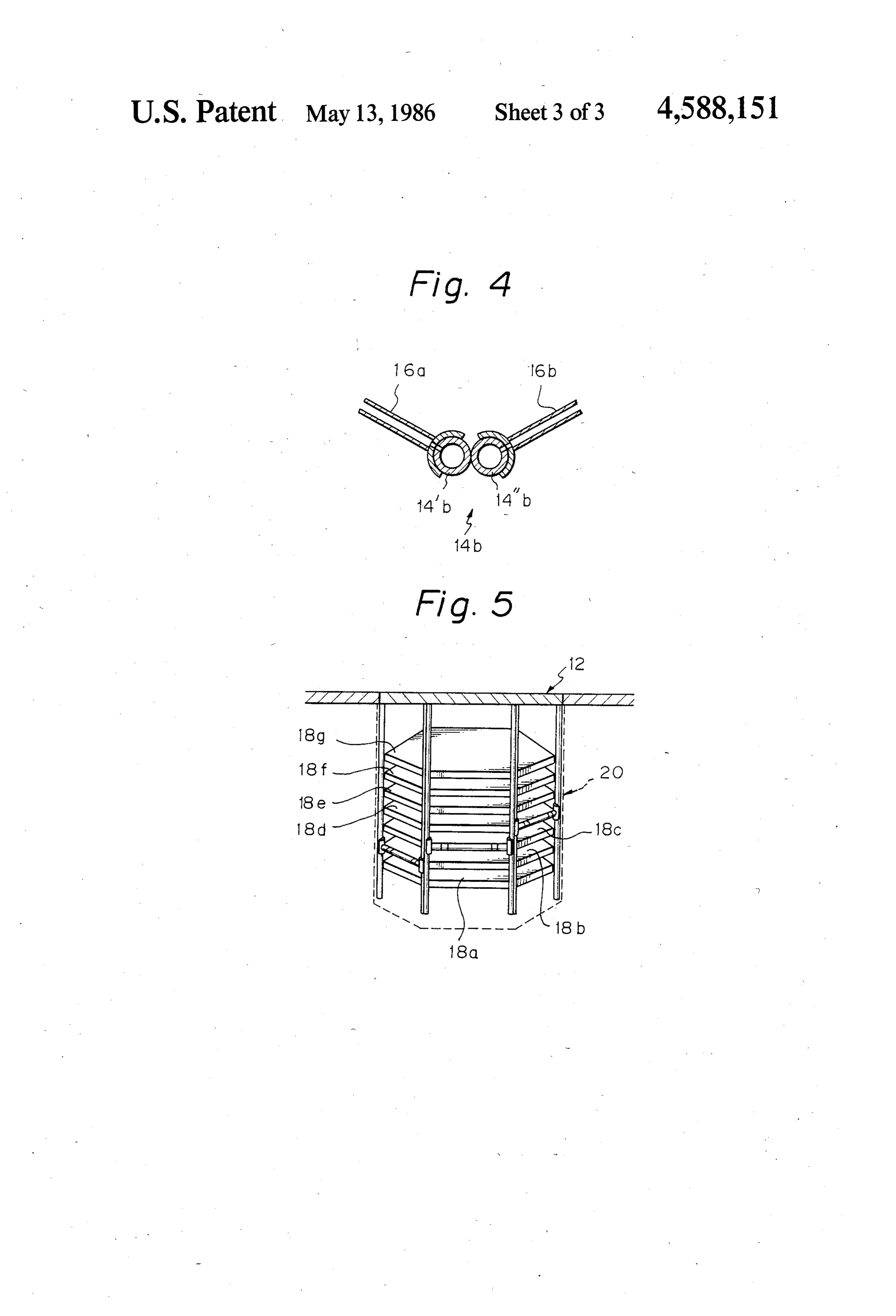
BRIEF DESCRIPTION OF THE DRAWINGS 65 Referring to FIG. 4, an encircled portion A of the FIG. 1 is a perspective view of a solar ray collector solar collector shown in FIG. 1 is shown in an enlarged embodying the present invention which is in an un sectional plan view, representing the configuration of folded operative position; the posts 14a-14f and their associated cross-arms
Page 6
16a-16g. As shown, the post 14b in the portion A is any desired sequence if the subassembly 18a is posi made up of two hollow tubular members, or pipes, 14"b tioned at the bottom of the stack. In this sense, the and 14'b which are joined together in a generally co movement of the subassembly 18a along the posts 14e coon shape. The cross-arms 16a and 16b, which are also and 14f is not an essential feature and, instead, the subas holow, respectively grip the pipes 14b and 14'b and are sembly 18a may be securely mounted in lower portions slide up and down therealong. This configuration ap of the posts 14e and 14f plies to all the other associated posts and cross-arms. Although not shown in the drawings, stops are rig The construction shown in FIG. 4 allows all the fiber idly mounted on the tops of the posts 14a-14fin order to optic cables 34 associated with the collector subassem prevent the cross-arms 16a-16f from slipping off the blies 18a-18g to be led through the bores inside the 10 posts i4a-14f when they are raised to the top of the cross-arms 16a-16g and posts 14-a-14f Solar radiation assembly.
collected by the collector subassemblies 18a-18g are The light receiving surfaces of the subassemblies transmitted by the cables 34 in the cross-arms and posts 18a-18g are oriented sunward relying on a posture con to the interior of the spacecraft. While the posts 14a-14f trol performed by the spacecraft.
have been shown and described as each being made up In summary, it will be seen that the present invention of two pipes, they may comprise a single hollow mem 15 provides a solar ray collector which is suitable for use ber having a general cocoon-shaped cross section. with a spacecraft due to the need for a minimum of Each of the hollow posts 14a-14f has thereinside a space. Designed for use in the space, the solar ray col drive mechanism for moving its associated cross-arms lector of the present invention has no gravity during 16 up and down, while each of the cross-arms 16a-16g operation and, therefore, requires only a small driving has thereinside a drive mechanism for rotating its asso 20 force for raising and lowering and rotating the subas ciated collector subassembly 18. When in use, the col semblies 18a-18g as described. Such a situation also lector subassemblies 18a-18g are moved out of the hous allows the subassemblies 18a-18g to be cantilevered ing section 20 and, when out of use such as at the time each at one end only.
of launching, they are kept in the housing section 20. Various modifications will become possible for those The folded inoperative position of the collector sub 25 skilled assemblies 18a-18g is shown in FIG. 5. An exemplary present indisclosure the art after receiving the teachings of the without departing from the scope and not restrictive example of the procedure for folding thereof.
the collector subasemblies 18a–18g from the FIG. 1 What is claimed is:
position to the FIG. 5 position will be described. First, 1. A solar ray collector adapted to be used for a the cross-arm 16g carrying the subassembly 18a there 30 spacecraft, comprising:
with is lowered along the posts 14e and 14fto a lower support means connected to the spacecraft, said sup most position in the assembly. Then, the cross-arm 16a, porting means being extended outside the space for example, is elevated along the posts 14a and 14b to craft in use, said supporting means being formed of an uppermost position in the assembly. Subsequently, at least three posts arranged parallel to each other the subassembly 8b is rotated 180 degrees about the 35 so that the distance between each adjacent two cross-arm 16a and over the tops of the posts 14a and 14b posts is equal to each other, until the subassembly 18b settles itself in the hexagonal a plurality of holding means connected to and moved region defined by the posts 14a-14f. In this position, the along the supporting means, each holding means cross-arm 16a is lowered along the posts 14a and 14b to having an axis and being rotatable relative to the lay the subassembly 18b over the subassembly 18a. By 40 the same procedure, the other subassemblies 18c-18g axis, each holding means being in the form of a are sequentially elevated to the upper ends of their shaft situated between a respective adjacent two of associated posts, rotated 180 degrees, and then lowered the posts and extending perpendicular to the posts, along the posts to be stacked in the hexagonal space. and
Thereafter, the posts 14a-14fare lowered together so 45 a plurality of collector means each connected to a that the whole assembly 10 is bodily retracted into the respective holding means so that the collector housing section 20. The top opening of the housing means are independently movable and rotatable section 20 may be closed by a lid (not shown). relative to the supporting means, each collector At the time of launching the spacecraft or collecting means having a light receiving surface to receive it, all the collector subassemblies 18a-18g are efficiently 50 solar rays thereon, the light receiving surface being stored in a stack inside the housing section 20 as previ of a configuration substantially corresponding to ously stated. After the spacecraft has reached the space, an area perpendicular to and surrounded by the the solar collector 10 is unfolded to its operative posi posts, said shaft being movable along and rotatable tion shown in FIG. 1 by the steps of opening the lid (not relative to the posts so that when the collector shown) of the housing section 20, projecting the stack 55 means are not used, the collector means are held in of subassemblies 18a-18g together with the posts an area surrounded by the posts, and when the 14a-14f to the outside of the spacecraft, and causing the collector means are used, the collector means are previously mentioned folding procedure to occur in the located substantially outside the area surrounded reverse sequence, that is, sequentially elevating the by the posts.
subassemblies 18g-18b and rotating them 180 degrees in 2. A solar ray collector according to claim 1, in the opposite direction. which said supporting means is formed of six posts so In the unfolded position of the solar collector 10, the that the area perpendicular to and surrounded by the subassemblies 18b-18g may lie in the same plane with posts is hexagonal.
the subassembly 18a positioned in the lowermost por 3. A solar ray collector according to claim 1, in tions of the associated posts 14e and 14f. However, any which each collector means comprises a plurality of positional relationship between the subassemblies 65 lenses and optical fibers having light receiving ends, 18a-18g with respect to height is permissible so long as each of said light receiving ends being located on the their light receiving surfaces are directed on the sun. focal point of a respective one of the lenses. Also, the subassemblies 18a-18g may be folded down in sk sk r k k
Provenance
- Collection
- Cited prior art
- Original PDF
- patentimages.storage.googleapis.com →
- Filed
- 1984-07-12
- Pages
- 6
- Method
- pdftotext (the PDF's own text layer) + pdftoppm 300dpi page scans
- Source
- Google Patents bibliographic record
- Granted
- 1986-05-13
- Inventors
- Kei Mori
- Transcribed from
- patentimages.storage.googleapis.com →