patent · US4106952
Solar panel unit
15 August 1978
Page 1 — bibliographic record
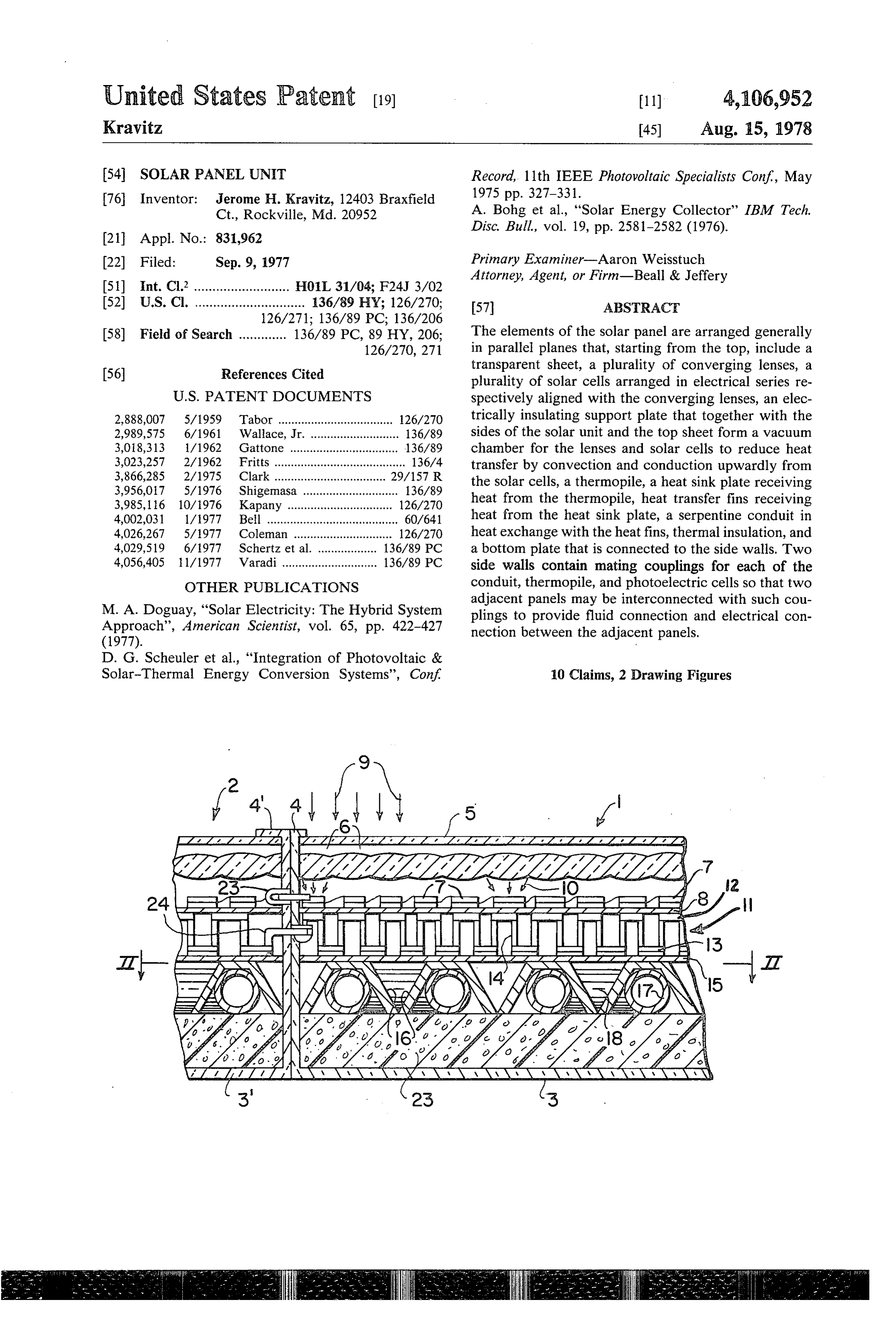
United States Patent (19) 11) 4,106,952 Kravitz, 45) Aug. 15, 1978 54 SOLARPANEL UNIT Record, 11th IEEE Photovoltaic Specialists Conf, May 76 Inventor: Jerome H. Kravitz, 12403 Braxfield 1975 pp. 327-331.
Ct., Rockville, Md. 20952 A. Bohg et al., "Solar Energy Collector” IBM Tech.
22 Filed: Sep. 9, 1977 Primary Examiner-Aaron Weisstuch Attorney, Agent, or Firm-Beall & Jeffery 51) int. C.? .......................... H01L 31/04; F24J 3/02 52 U.S. Cl. .............................. 136/89 HY; 126/270; 57 ABSTRACT
58) Field of Search ............. 136/89 PC, 89 HY, 206; The elements of the solar panel are arranged generally 126/270, 271 in parallel planes that, starting from the top, include a
transparent sheet, a plurality of converging lenses, a plurality of solar cells arranged in electrical series re
2,888,007 5/1959 Tabor ................................... 126/270 trically insulating support plate that together with the 2,989,575 6/1961 Wallace, Jr. ........................... 136/89 sides of the solar unit and the top sheet form a vacuum 3,018,313 /1962 Gattone ................................. 136/89 chamber for the lenses and solar cells to reduce heat 3,023,257 2/1962 Fritts ........................................ 136/4 transfer by convection and conduction upwardly from 3,866,285 2/1975 Clark .................................. 29/157 R the solar cells, a thermopile, a heat sink plate receiving 3,956,017 5/1976 Shigemasa ............................. 36/89 heat from the thermopile, heat transfer fins receiving 3,985, 116 10/1976 Kapany ...... ... 126/270 4,002,031 1/1977 Bell ........................................ 60/641 heat from the heat sink plate, a serpentine conduit in 4,026,267 5/1977 Coleman .............................. 126/270 heat exchange with the heat fins, thermal insulation, and 4,029,519 6/977 Schertz et al. .................. 136/89 PC a bottom plate that is connected to the side walls. Two 4,056,405 1/1977 Varadi ............................. 136/89 PC side walls contain mating couplings for each of the OTHER PUBLICATIONS conduit, thermopile, and photoelectric cells so that two adjacent panels may be interconnected with such cou
M. A. Doguay, "Solar Electricity: The Hybrid System plings to provide fluid connection and electrical con Approach'', American Scientist, vol. 65, pp. 422-427 nection between the adjacent panels.
D. G. Scheuler et al., "Integration of Photovoltaic &
Solar-Thermal Energy Conversion Systems', Conf 10 Claims, 2 Drawing Figures
HgIII
E7SN SY
Page 2
Drawing sheet — no readable text.
Page 3
Since the solar panel unit 1 and solar panel unit 2 are
SOLAR PANEL UNIT of identical construction, the same numerals will be BACKGROUND OF THE INVENTION used for the two panels, with primes being used for the numerals of panel two, and the description of one will
The present invention relates to a solar panel unit that 5 suffice for the other.
may collect solar energy and convert it into a more The solar panel unit 1 has an upwardly opening en reusable energy form, such as electrical energy or a closure formed by a bottom wall 3 and side walls 4 heated liquid. extending around the entire periphery of the bottom Due to the increase in cost and depletion of fossil wall 3. The top of the enclosure is closed by means of a fuels, other energy sources are becoming increasingly 10 self supporting sheet of material transparent to Solar important, and the use of solar energy has great poten radiant energy, for example glass 5. Immediately be tial. One of the main problems with the solar panels neath and parallel to the glass 5, there is a sheet of mate employed today is that their efficiency is relatively low rial transparent to solar radiant energy and providing a so that a large surface area is required to produce a plurality of circular, as seen in plan view, lenses 6. The usable quantity of energy. 15 lenses 6 may be of the same construction as those shown
SUMMARY in U.S. Pat. No. 3,929, 121 issued Dec. 30, 1975. Immedi ately beneath the lenses 6, there are provided a plurality
It is an object of the present invention to produce a of electrically serially interconnected photoelectric more efficient solar panel, so that thereby for a given 20 cells 7, which may be of identical construction to and quantity of desired usable energy, the area of solar panel interconnected in the same manner as the photoelectric required will be at a minimum. cells of U.S. Pat. No. 4,002,031 issued Jan. 11, 1977. Lenses are provided to concentrate the solar energy Beneath the cell 7, there is provided a support plate 8, onto photoelectric cells for the production of electric which is constructed of electrically insulated material ity, and the heat that is necessarily produced is pre 25 that has good thermal conductivity. The plate 8 and top vented from leaving the system, to a large extent, by an 5 are sealingly connected around their entire peripher evacuated chamber while at the same time reflected ies to the side walls 4, so as to form with the side walls radiation is limited due to the greenhouse effect of the 4 a hermetically sealed enclosure that is evacuated so as top transparent sheet that assists in the formation of the to greatly decrease heat transfer by conductivity or evacuated chamber. The heat thus produced is con 30 convection from the photoelectric cells 7 to the top ducted downwardly to a thermopile where it is partially plate 5.
converted to electricity, and further conducted down As shown, the unit would be arranged so that prefera wardly to where it is used to finally heat water that may bly the solar radiant energy as indicated by arrows 9 be used in the hot water system of a residence or for will pass through the transparent plate 5 in a direction space heating purposes at a remote location. Thermal 35 perpendicular to the plane of the plate 5 and be concen insulation is provided below the water pipes. trated by means of the lenses 6 so as to converge in The panels are provided with electrical and fluid concentrated beams 10 onto the individual photoelec couplings so that adjacent panels may be connected tric cells 7, with a number of lenses preferably being together. equal to the number of vertically aligned photoelectric BRIEF DESCRIPTION OF A PREFERRED 40 cells 7. In this manner, the majority of the solar radia EMBODIMENT tion will strike the photoelectric cells 7 so as to produce electricity in each of the cells, with the cells being seri
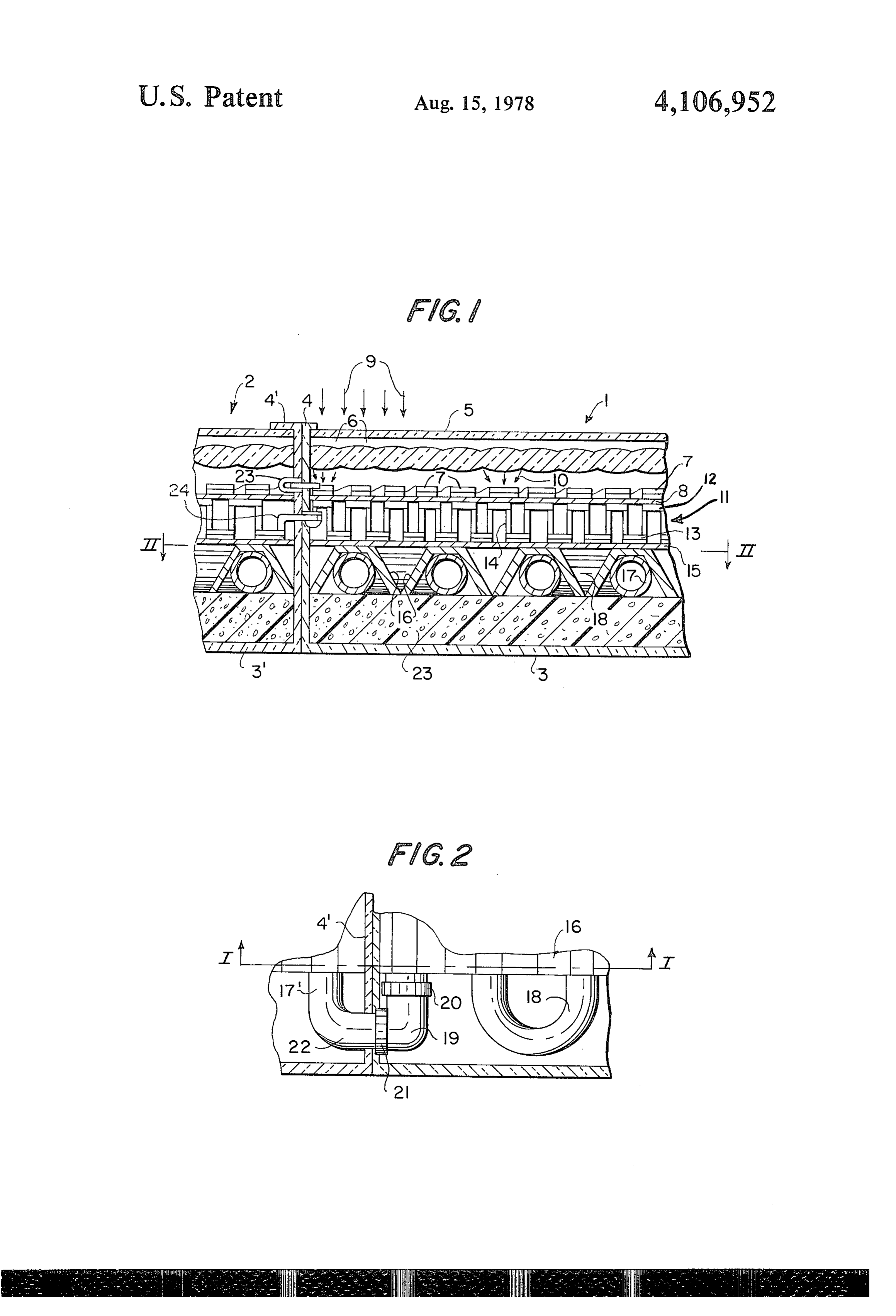
Further objects, features and advantages of the pres ally connected so as to produce a useful voltage be ent invention are shown in the accompanying drawing, tween the positive and negative electrical terminals of which shows a preferred embodiment that is at the 45 the serially connected photoelectric cells 7 of each unit. present time the best known mode of construction. Any radiation that does not strike the photoelectric FIG. 1 is a partial cross sectional elevational view of cells 7 will strike the support plate 8, which is prefera two adjacent solar panels constructed according to the bly black to absorb the radiation and convert it into present invention, and as taken along line I-I of FIG. heat. Since the enclosure formed by the plates 5, 8 and 2; and 50 side walls 4 is evacuated, the heat generated within the FIG. 2 is a partial cross sectional view taken along photoelectric cells 7 and the plate 8 will be conducted line II-II of FIG. 1. downwardly.
DETAILED DESCRIPTION OF A PREFERRED Beneath the support plate 8, there is a thermopile 11 EMBODIMENT that is preferably of the same construction as shown in
FIGS. 1 and 2 disclose portions of two adjacent and conductors 12 of the thermopile are connected to the intercoupled solar panel units, which are of identical bottom conductors 13 by means of thermocouples 14 in construction. For example, the portion shown of the left a known manner so that the thermopile will produce a hand unit could be joined to the right side of the portion substantial useful voltage at its positive and negative of the right hand unit to represent a single complete 60 output terminals according to the number of thermo unit, and because in this manner a single unit is com couples connected in series, while transferring heat pletely shown effectively, portions of each unit have from the support plate 8 downwardly to the conductors been removed to simplify the disclosure. In plan view, 12 and from there to the conductors 13. The conductors each unit would preferably be of rectangular configura 13 are in direct engagement with a heat sink plate 15 tion, so that a plurality of such units could be intercon 65 that forms the cold junction of the thermopile. Prefera nected across a roof or other support to form a compos bly, the heat sink plate 15 is hermetically sealed around ite solar collecting panel of a desired cross sectional its entire periphery to the side walls 4, so that the area aca. containing the thermopile may be evacuated. If desired,
Page 4
the support plate 8 need not be hermetically sealed to area, the exposed couplings at the outer sides of the the side walls 4 if the heat sink plate 15 is sealed. composite may be interconnected by fluid conduits and Any heat that has not been converted into electrical electrical conductors respectively either in series or energy with the thermopile is received by the heat sink parallel as desired.
plate 15 and conducted downwardly by means of heat Water or some other liquid may be passed through exchange fins 16 that are preferably bonded to the the serially connected pipe 17 to be heated, and this hot lower surface of the heat sink plate 15 on their upper water may be stored to be used as needed for the heat end and extend downwardly so as to substantially sur ing of enclosures through hot water radiators or for round the parallel portions of a serpentine pipe 17, with supplying hot water for domestic use such as showers. the fin 16 and pipe 17 being joined by solder or the like 10 The use of hot water for heating purposes and domestic to improve the heat transfer. As shown in FIG. 2, U consumption is shown in U.S. Pat. No. 2,946,945 issued shaped bends 18 of the pipe 17 joined the ends of the July 26, 1960. Also, the hot water produced may be parallel straight sections of the pipe 17 to form one used in heat exchange with a fluid to be evaporated for single serpentine conduit for each solar panel unit. One the running of a turbine, as disclosed in U.S. Pat. No. end of the conduit is provided with a right angle joint 15 4,002,031 issued Jan. 11, 1977. 19, having its portion 20 permanently secured to the one The electrical energy produced by the photoelectric end of the conduit and its portion 21 providing a releas cells and the thermopile may be stored in a battery for able conduit coupling. The portion 20 may be soldered later usage as disclosed in U.S. Pat. No. 2,946,945 issued to its end of the pipe 17, whereas the portion 21 may July 26, 1960. Also, the electricity produced by the include an aperture of the same diameter as the pipe 17 20 thermopile and photoelectric cells may be employed as provided with an O-sealing ring to form a fluid tight the electrical energy source for the system disclosed in seal with pipe 17 inserted within the end 21. The oppo U.S. Pat. No. 3,459,953 issued Aug. 5, 1969 for the site end of the conduit is provided with a right angle production of hydrogen and oxygen through electroly bend 22 to provide a coupling portion extending beyond sis, which gases are stored and later withdrawn to be the side wall of its unit, so as to be telescopically re 25 burned to produce products of combustion for driving a ceived in sealing engagement within the coupling 19. In gas turbine that in turn drives an electrical generator this manner, two adjacent solar panel units may be fluid providing electrical energy for usage as desired, with interconnected so that their serpentine pipes will be the products of combustion being condensed after pass serially connected. ing through the turbine to provide pure water that may In the event that the solar panel unit is to be exposed 30 either be a source of pure water for any desired purpose to the environment, and the environment is to upon or a source of water for the electrolysis unit. occasion drop below freezing at time when solar energy The disclosure of the above mentioned patents is is not available, for example at night, it is desirable to incorporated herein in its entirety for the purposes men provide thermal insulation 23 below the pipes 17, which tioned to produce the entire solar energy conversion insulation will also insure that the heat reaching the pipe 35 system of the present invention. 17 will not travel any further downwardly to any sub In operation, the solar panel unit of the present inven stantial extent. tion is designed to extract approximately 76% of the As mentioned above, the serial array of photoelectric solar energy striking it, and to convert the energy into cells 7 will have, for each solar panel unit, a positive other forms of more usable energy. The extraction-con electrical output terminal and a negative electrical out 40 version process is accomplished in three separate stages, put terminal. Preferably, one of such terminals will be with each stage employing a different type of process. provided with a releasable coupling part so as to extend The first stage involves the use of photoelectric conver through the side wall having the fluid coupling 19, sion through the employment of solar batteries, photo whereas the other part of a mating releasable electrical voltaic cells, or photoelectric cells, which all broadly coupling will be electrically connected to the other 45 are referred to in the present invention as photoelectric terminal so as to extend through the side wall having cells, meaning transducers that will receive direct solar the releasable fluid coupling 22, with such electrical radiant energy and convert it directly into electrical coupling parts being in corresponding locations so that energy. The second stage involves the use of thermo they will interconnect when the fluid couplings 19, 22 electric conversion whereby heat differentials are con interconnect. Such electrical couplings may be conven 50 verted into electric power, and in the present invention tional bayonet connections or the like. In the same man the term thermopile is used to broadly indicate such a ner, the output terminals of the thermopiles are con device that directly converts heat into electricity. The nected between adjacent units with releasable electrical third stage acts as a heat sink for the second stage as the coupling 24. Thus, the positive output terminal of the cold terminal, and in so doing heats cold water which is serially arranged photoelectric cells 7 of unit 1 may be 55 then stored in hot water facilities. The hot water can electrically connected through releasable electrical later be used for the heating of a home or for other hot coupling 23 to the negative output terminal of the pho water requirements of a dwelling.
toelectric cells 7 of the unit 2, one of the positive and Although solar energy varies greatly depending upon negative electrical terminals of the thermopile 11 may a number of conditions, a valid assumed rate of 1 Lang be connected through releasable electrical coupling 24 60 ley radiation per minute for many locations in the to the other of the positive and negative terminals of the United States appears to be a reasonable working esti thermopile 11" of unit 2, and the downstream end of mate. Thus, a square meter receives approximately 10 pipe 17 may be connected through releasable fluid cou kcal per minute of solar radiation. Over the span of one pling 19, 22 to the upstream end of pipe 17 of unit 2, all average bright day (8 hours radiation) a home roof of of which may be accomplished by merely aligning the 65 approximately 1,000 square feet will receive approxi units 1 and 2 and horizontally pushing the units together mately 500,000 kcal of energy. This is roughly equiva to telescopically engage their couplings. When an entire lent to 13 or 14 gallons of gasoline. With an extraction composite of panels has been assembled for the desired conversion process having 76% efficiency, the average
Page 5
home would on a bright day be able to produce the support means between said array of photoelectric equivalent of 9.88 gallons of gasoline. Of course, if more cell means and said thermopile means for electri energy were required this would simply entail enlarging cally insullating said thermopile means from said the unit. photoelectric cell means, for conducting heat The efficiency of the present invention is in part ac 5 downwardly, and converting any radiant energy complished by the top wall 5 that will admit most of the directly received thereon into heat; radiant energy and prevent reradiation of the wave a planar heat sink means immediately below said length through a greenhouse effect. That is, the material thermopile means for receiving and transmitting of the cover or top wall 5 will transmit the long wave downwardly the heat transmitted by said thermo lengths of light, allowing them to enter the unit, but will 10 pile means; and not transmit the short wave lengths of reflected or rera liquid conduit means beneath and in heat exchange diated energy, thereby trapping the energy within the relationship with said heat sink means. unit. Some of the radiant energy will be directly con 2. The solar energy conversion system of claim 1, verted to electricity by the photoelectric cell 7, whereas including side walls around the entire periphery of Said the rest of the energy trapped within the unit will be 15 top sheet, photoelectric cell means, support means, converted to heat. Because of the insulation 23, which thermopile means, heat sink means and conduit means may be rigid foam plastic, for example polystyrene, and to form an enclosed unit; one of said side walls having a the evacuation of the chamber between the sheets 5 and first releasable electrical coupling part electrically con 8 at least, or between the sheets 5 and 15, there will be 20 nected to one of the electrical terminals of said thermo very little loss of heat through conduction and convec pile means, a second releasable electric coupling part tion. electrically connected to one of the electrical terminals The solar battery units will be preferably of semicon of said photoelectric cell means, and a first conduit ductive material with a conversion efficiency of 10%. coupling part fluid connected to one end of said conduit means; another of said side walls having a third releas
The thermopile will use some of the heat to produce 25 able electrical coupling part of a mating configuration electricity and conduct the remainder of the heat down wardly through the unit. The thermopile is constructed, with said first releasable electrical coupling part being electrically connected to the other of the electrical in a known manner, of a plurality of thermocouples terminals of said thermopile means, and being at a loca having two dissimilar metals or semiconductors joined tion to register with so as to produce a hot junction (above) and a coldjunc 30 a horizontally alignedtheandfirstimmediately electrical coupling part of adjacent identi tion (below), which will produce electricity. When the cal unit; said another side wall having a fourth thermocouples are arranged in series, the electricity coupling part of a mating configuration with electrical will be of a substantial usable voltage. The conversion ond releasable electrical coupling part, beingsaid sec electri efficiency of such a thermopile is approximately 10%. cally connected to the other of the electrical terminals The heat sink that is necessary for a thermopile is pro 35 of said series connected photoelectric cell means, and vided by the metal plate 15 and the heat withdrawn by being at a location to register with the second releasable the water passing through the pipe 17, with the usable electrical coupling part of the horizontally aligned and heat in the water raising the efficiency of the entire unit immediately adjacent identical unit; said another side up to the above mentioned approximately 76%. wall further having second conduit coupling part of The fluid and electrical connections between some of 40 complementary mating shape to said first conduit cou the units may also be in parallel instead of in series, as pling part, fluid connected to the opposite end of said desired, particularly along the outer edges of the assem conduit means, and being at a location so as to matingly bled units; some of the connections internally of a unit register with the first conduit coupling part of the hori may be in parallel. For optimum light collection, the zontally aligned immediately adjacent identical unit. side walls 4, 4 may also be transparent, and the side 45 3. The solar energy conversion system of claim 2, walls 4, 4 may be formed in one piece with the top 5 to including a planar array of converging lenses spaced be closed by a separate bottom 3. below and parallel to said top sheet for receiving the While a preferred embodiment has been shown in solar radiant energy passing through said top sheet and detail for purposes of illustrating the best mode known producing a plurality of radiant energy concentrations at the present time, further embodiments, variations and 50 respectively on said plurality of photoelectric cell modifications are contemplated according to the CaS.
broader aspects of the present invention, all is deter 4. The solar energy conversion system of claim 2, mined by the spirit and scope of the following claims. comprising a layer of thermal insulation immediately What is claimed is: beneath said conduit means.
1. A solar energy conversion system, comprising: 55 5. The solar energy conversion system of claim 2, a top fluid impervious sheet that freely passes solar including means including said top sheet for forming a radiant energy; hermetically sealed vacuum enclosure having therein at a plurality of photoelectric cell means arranged in a least said photoelectric cell means for reducing heat plane spaced below and parallel to said top sheet transfer by convection and conduction upwardly away for receiving the solar radiant energy and directly 60 from said photoelectric cells and said support means. converting a portion into electricity and convert 6. The solar energy conversion system of claim 2, ing substantially the remainder into heat; including said conduit means comprising a metallic pipe means electrically connecting said photoelectric cell arranged in a serpentine path within a single plane par means in a power producing circuit; allel to and closely spaced to said heat sink means; and a thermopile means below said photoelectric cell 65 a plurality of heat transfer fins bonded to the lower means for receiving the heat, converting a portion surface of said heat sink means and extending down of the heat into electrical energy, and transmitting wardly to partially surround at least a major portion of the remainder of the heat downwardly; said pipe.
Page 6
7. The solar energy conversion system of claim 1, least said photoelectric cell means for reducing heat including a planar array of converging lenses spaced transfer by convection and conduction upwardly away below and parallel to said top sheet for receiving the from said photoelectric cells and said support means. solar radiant energy passing through said top sheet and 10. The solar energy conversion system of claim 1, producing a plurality of radiant energy concentrations including said conduit means comprising a metallic pipe respectively on said plurality of photoelectric cell arranged in a serpentine path within a single plane par
8. The solar energy conversion system of claim 1, allel to and closely spaced to said heat sink means; and including a layer of thermal insulation immediately a plurality of heat transfer fins bonded to the lower beneath said conduit means. 10 surface of said heat sink means and extending down 9. The solar energy conversion system of claim 1, wardly to partially surround at least a major portion of including means including said top sheet for forming a said pipe.
hermetically sealed vacuum enclosure having therein at sk : k :
Provenance
- Collection
- Cited prior art
- Original PDF
- patentimages.storage.googleapis.com →
- Filed
- 1977-09-09
- Pages
- 6
- Method
- pdftotext (the PDF's own text layer) + pdftoppm 300dpi page scans
- Source
- Google Patents bibliographic record
- Granted
- 1978-08-15
- Inventors
- Jerome H. Kravitz
- Transcribed from
- patentimages.storage.googleapis.com →