patent · US4483311
Solar power system utilizing optical fibers, each fiber fed by a respective lens
20 November 1984
Page 1
r (. . . ; S
i f is 4. XR (; ; ; ; 3. s. 3,
United States Patent (19) 11 Patent Number: 4,483,311 Whitaker 45 Date of Patent: Nov. 20, 1984 54 SOLAR POWER SYSTEM UTILIZNG 4,201,197 5/1980 Disner ................................ 126/451 OPTICAL FIBERS, EACH FIBER FED BY A 4,282,858 8/1981 Bowers ............................... 126/440 RESPECTIVE LENS FOREIGN PATENT DOCUMENTS 76 Inventor: Ranald O. Whitaker, 4719 Squire 5714031 2/1979 Japan. Dr., Indianapolis, Ind. 46241
Primary Examiner-Carroll B. Dority, Jr.
21 Appl. No.: 521,291 57 ABSTRACT
A mosaic of lenses is oriented to face the sun. Each lens
Related U.S. Application Data focuses a solar image upon the open end of a respective optical fiber. The several fibers converge to form a 63) Continuation-in-part of Ser. No. 304,182, Sep. 21, 1981, bundle. The bundle passes to a receiver generally inside abandoned, which is a continuation-in-part of Ser. No. a building. The radiation delivered by the bundle may
tinuation-in-part of Ser. No. 82,906, Oct. 9, 1979, aban be used for cooking, lighting, operation of a thermody doned. namic engine, or other similar application. In the pre 51 Int, Cli................................................. F24J 3/02 ferred system the lens mosaic is a plastic sheet into 52) U.S. C. ................................. 126/440; 350/96.24; which lenses have been molded. In a first auxiliary 350/96.25 system the lens mosaic is formed on the front surface of 58 Field of Search ............................... 126/440, 451; a transparent plate. Solar images are formed on the rear 350/96.24, 96.25, 96.18 surface. Optical fibers are attached where these solar images are formed. This eliminates two reflecting sur (56) References Cited faces, thereby increasing efficiency by 19%. In a second
truncated cones to transmit the radiation to the solar 3,603,723 9/1971 Tan ................................... 350/96.24 image positions.
3,780,722 12/1973 Swet .................................... 126/451 4,026,267 5/1977 Coleman ............................. 126/452 4,101,188 7/1978 Yevick ............................. 350/96.25 1 Claim, 4 Drawing Figures
Page 2
Drawing sheet — no readable text.
Page 3
Drawing sheet — no readable text.
Page 4
Drawing sheet — no readable text.
Page 5
In the system of Coleman a matrix of lenses each
SOLAR POWER SYSTEM UTILIZING OPTICAL estimated to be 600 mm in diameter is used. The resul FIBERS, EACH FIBER FED BY ARESPECTIVE tant focal length becomes
LENS
This application is a continuation-in-part of applica = 300 x 1.732
doned; which is a continuation-in-part of application = 520
which is a continuation-in-part of application Ser. No. The diameter of the solar image becomes
BACKGROUND
Conventional solar power systems utilizing optical The consequent number of fibers required in the bundle fibers generally employ a single large lens (or mirror). 15 becomes
An orientation system causes the lens to face the sun.
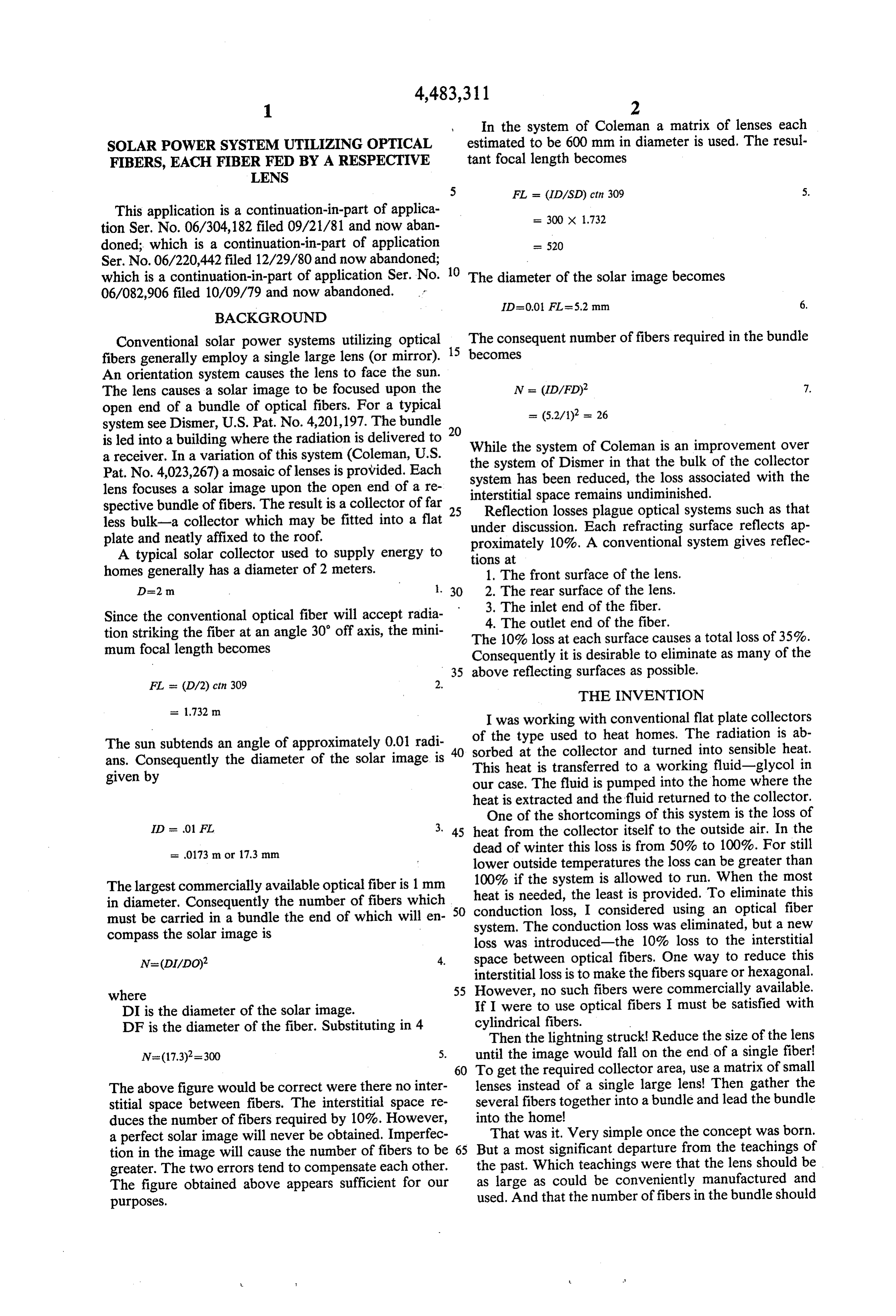
The lens causes a solar image to be focused upon the N = (ID/FD)2 7. open end of a bundle of optical fibers. For a typical = (5.2/1) = 26 system see Dismer, U.S. Pat. No. 4,201,197. The bundle 20 is led into a building where the radiation is delivered to While the system of Coleman is an improvement over a receiver. In a variation of this system (Coleman, U.S. the system of Dismer in that the bulk of the collector Pat. No. 4,023,267) a mosaic of lenses is provided. Each lens focuses a solar image upon the open end of a re system has been reduced, the loss associated with the interstitial space remains undiminished.
spective bundle of fibers. The result is a collector of far 25 Reflection losses plague optical systems such as that less bulk-a collector which may be fitted into a flat under discussion. Each refracting surface reflects ap plate and neatly affixed to the roof. proximately 10%. A conventional system gives reflec A typical solar collector used to supply energy to tions at homes generally has a diameter of 2 meters. 1. The front surface of the lens. D=2 m . 30 2. The rear surface of the lens. 3. The inlet end of the fiber.
Since the conventional optical fiber will accept radia 4. The outlet end of the fiber. tion striking the fiber at an angle 30' off axis, the mini The 10% loss at each surface causes a total loss of 35%. mum focal length becomes Consequently it is desirable to eliminate as many of the 35 above reflecting surfaces as possible.
THE INVENTION
I was working with conventional flat plate collectors of the type used to heat homes. The radiation is ab
The sun subtends an angle of approximately 0.01 radi 40 sorbed at the collector and turned into sensible heat. ans. Consequently the diameter of the solar image is This heat is transferred to a working fluid-glycol in given by our case. The fluid is pumped into the home where the heat is extracted and the fluid returned to the collector.
One of the shortcomings of this system is the loss of
ID se 01 FL 3. 45 heat from the collector itself to the outside air. In the
dead of winter this loss is from 50% to 100%. For still lower outside temperatures the loss can be greater than
The largest commercially available optical fiber is 1 mm heat100% if the system is allowed to run. When the most in diameter. Consequently the number of fibers which 50 conduction is needed, the least is provided. To eliminate this must be carried in a bundle the end of which will en loss, I considered using an optical fiber compass the solar image is system. The conduction loss was eliminated, but a new loss was introduced-the 10% loss to the interstitial space between optical fibers. One way to reduce this interstitial loss is to make the fibers square or hexagonal.
where 55 However, no such fibers were commercially available. DI is the diameter of the solar image. If I were to use optical fibers I must be satisfied with DF is the diameter of the fiber. Substituting in 4 cylindrical fibers.
Then the lightning struck Reduce the size of the lens
N=(17.3)2=300 5. until the image would fall on the end of a single fiber 60 To get the required collector area, use a matrix of small
The above figure would be correct were there no inter lenses instead of a single large lens! Then gather the stitial space between fibers. The interstitial space re several fibers together into a bundle and lead the bundle duces the number of fibers required by 10%. However, into the homel a perfect solar image will never be obtained. Imperfec That was it. Very simple once the concept was born. tion in the image will cause the number of fibers to be 65 But a most significant departure from the teachings of greater. The two errors tend to compensate each other. the past. Which teachings were that the lens should be The figure obtained above appears sufficient for our as large as could be conveniently manufactured and used. And that the number of fibers in the bundle should purposes.
Page 6
be sufficient for the end of the bundle to encompass the power, or just released into a room to provide both light solar image produced by that lens. and heat. Delivered radiation may be divided and fed to During the study of this matrix system-the lightning several using devices.
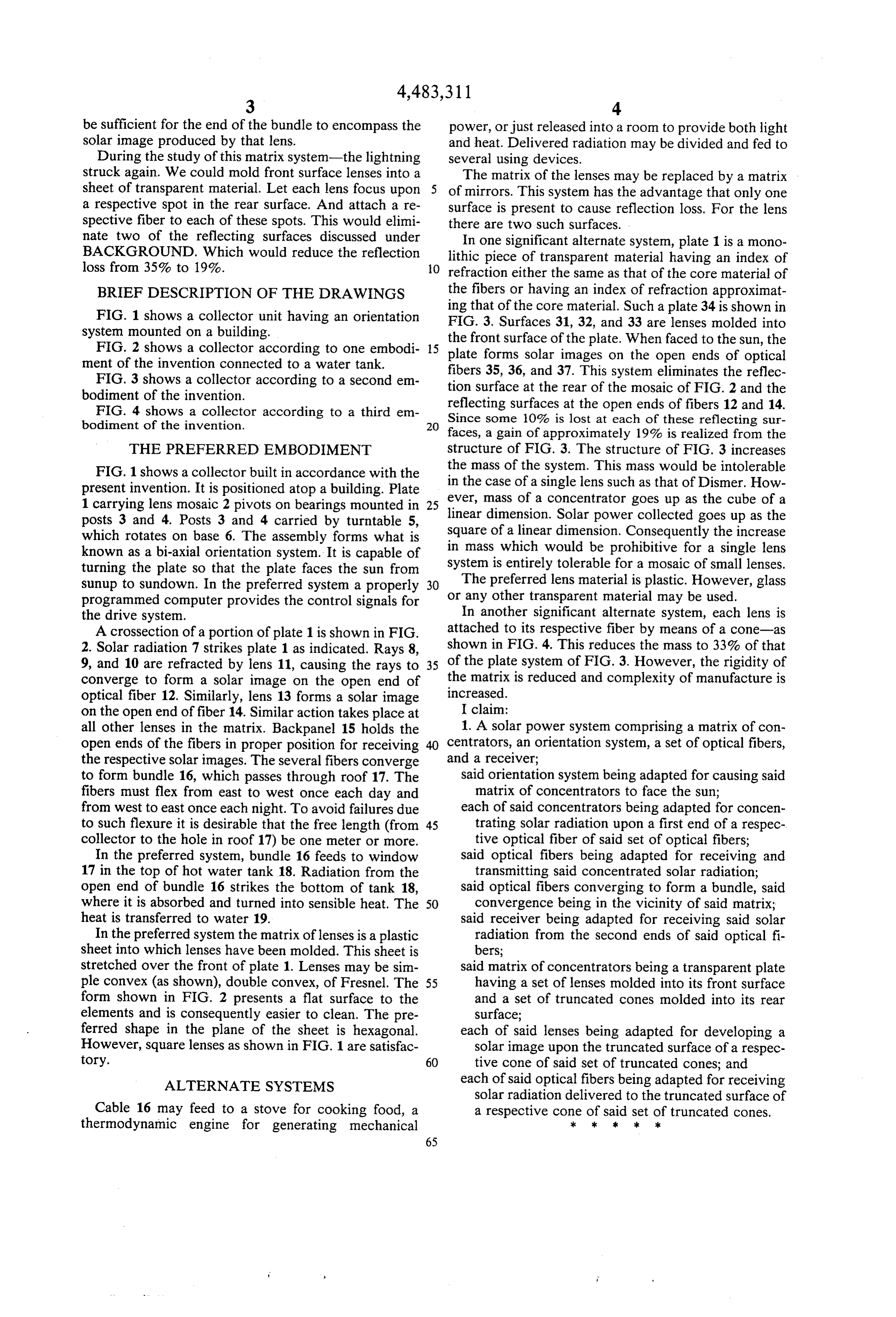
struck again. We could mold front surface lenses into a The matrix of the lenses may be replaced by a matrix sheet of transparent material. Let each lens focus upon of mirrors. This system has the advantage that only one a respective spot in the rear surface. And attach a re surface is present to cause reflection loss. For the lens spective fiber to each of these spots. This would elimi there are two such surfaces.
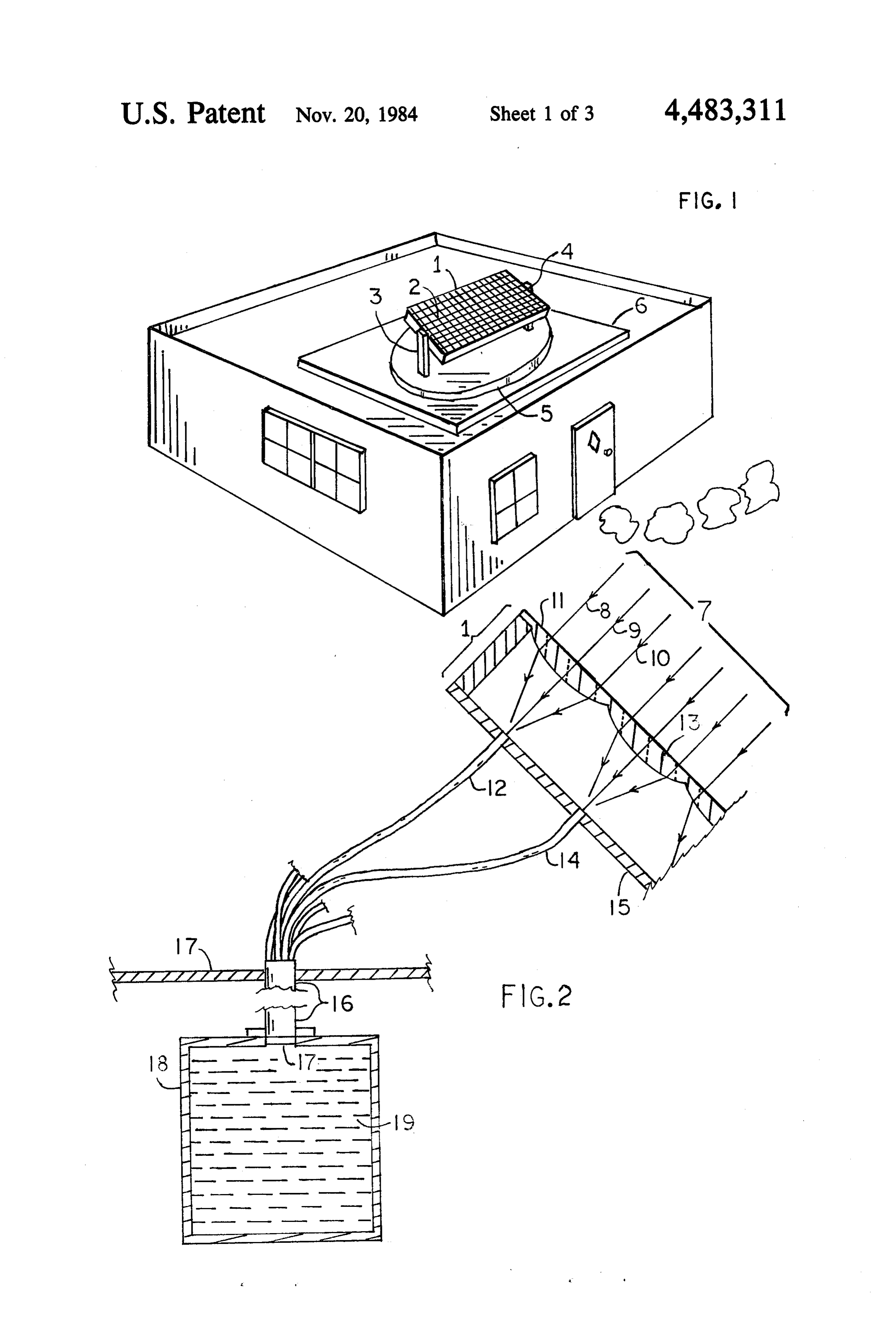
nate two of the reflecting surfaces discussed underIn one significant alternate system, plate 1 is a mono BACKGROUND. Which would reduce the reflection lithic piece of transparent material having an index of loss from 35% to 19%. O refraction either the same as that of the core material of BRIEF DESCRIPTION OF THE DRAWINGS the fibers or having an index of refraction approximat FIG. 1 shows a collector unit having an orientation ing
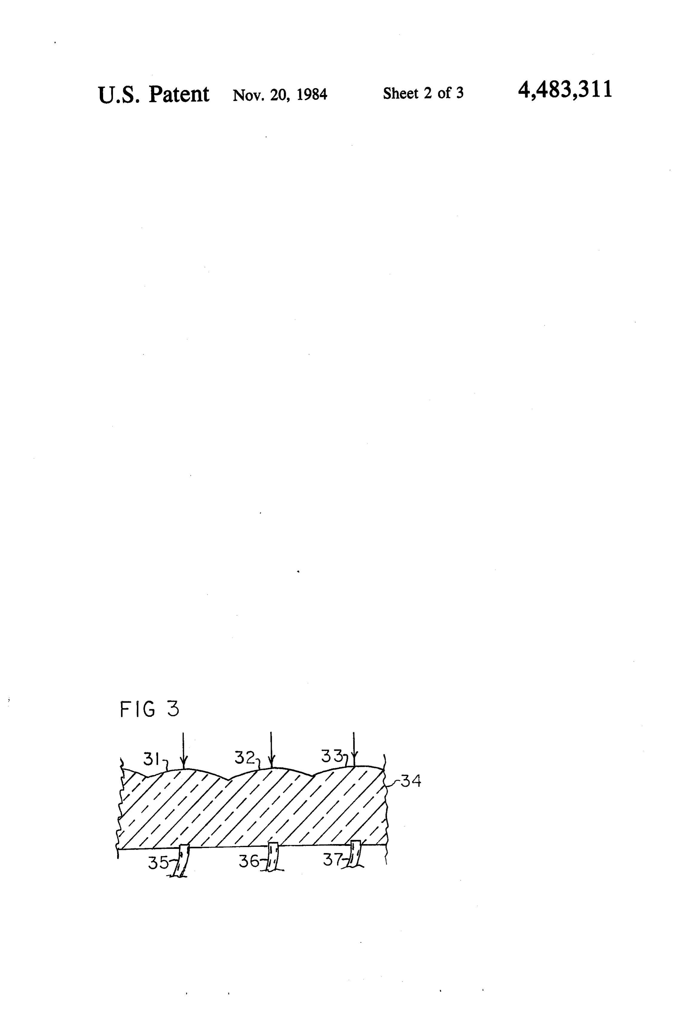
FIG.
that of the core material. Such a plate 34 is shown in 3. Surfaces 31, 32, and 33 are lenses molded into system mounted on a building. the front surface of the plate. When faced to the sun, the FIG. 2 shows a collector according to one embodi plate forms
solar images on the open ends of optical ment of the invention connected to a water tank.
FIG. 3 shows a collector according to a second em fibers 35, 36, and 37. This system eliminates the reflec tion surface at the rear of the mosaic of FIG. 2 and the bodiment of the invention.
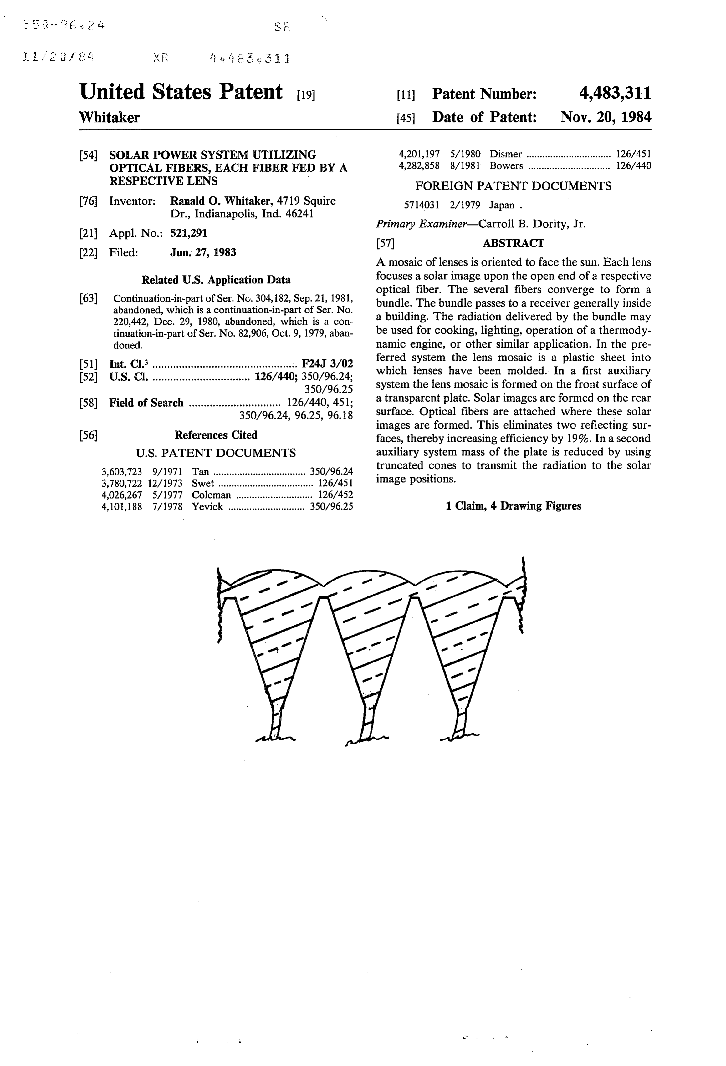
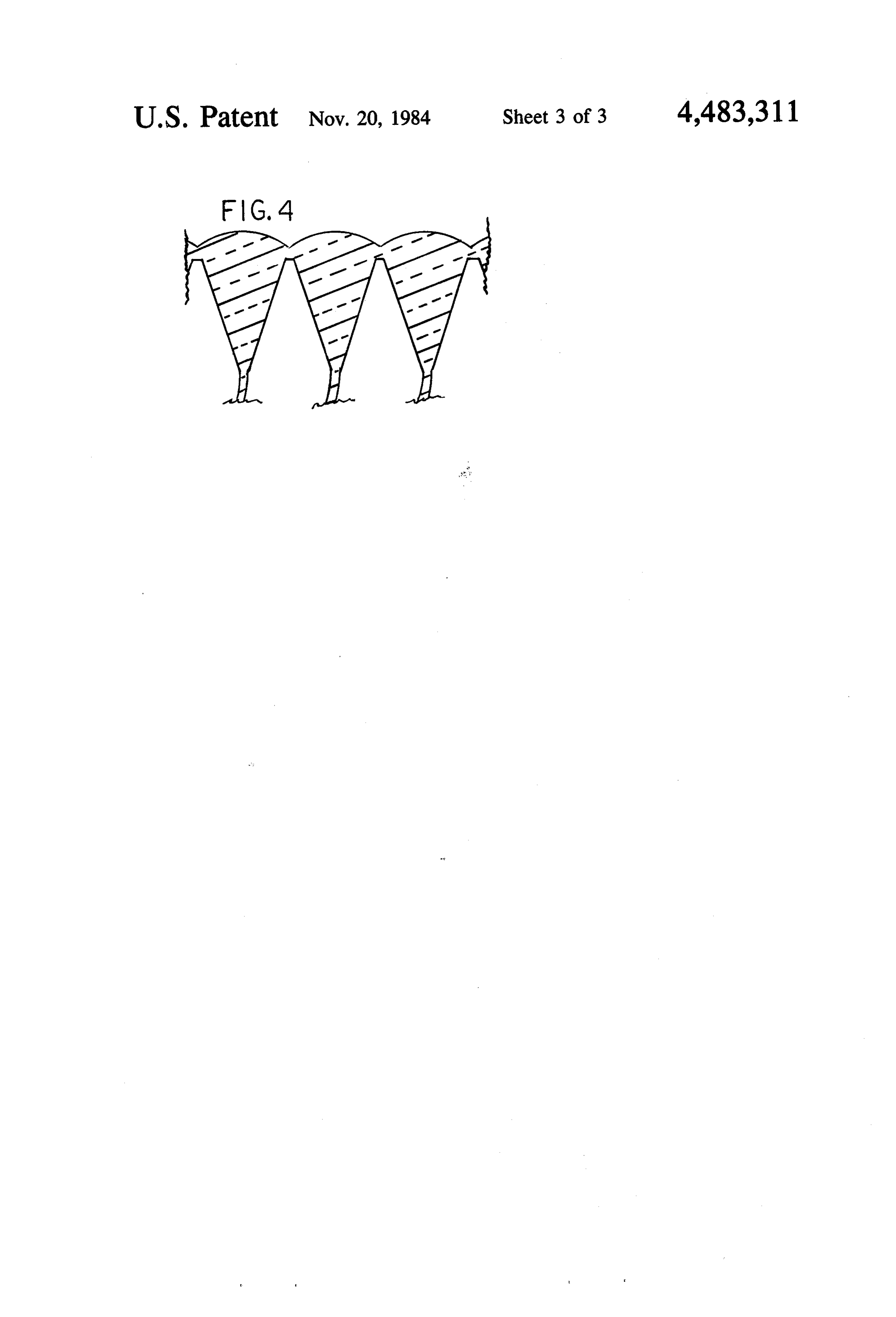
FIG. 4 shows a collector according to a third em reflecting surfaces at the open ends of fibers 12 and 14. bodiment of the invention. 20 Since some 10% is lost at each of these reflecting sur faces, again of approximately 19% is realized from the
THE PREFERRED EMBODIMENT structure of FIG. 3. The structure of FIG. 3 increases FIG. 1 shows a collector built in accordance with the the mass of the system. This mass would be intolerable present invention. It is positioned atop a building. Plate in the case of a single lens such as that of Dismer. How 1 carrying lens mosaic 2 pivots on bearings mounted in 25 ever, mass of a concentrator goes up as the cube of a posts 3 and 4. Posts 3 and 4 carried by turntable 5, squarelinear dimension. Solar power collected goes up as the which rotates on base 6. The assembly forms what is of a linear dimension. Consequently the increase known as a bi-axial orientation system. It is capable of in mass which would be prohibitive for a single lens turning the plate so that the plate faces the sun from system is entirely tolerable for a mosaic of small lenses. sunup to sundown. In the preferred system a properly 30 The preferred lens material is plastic. However, glass programmed computer provides the control signals for or any other transparent material may be used. the drive system. In another significant alternate system, each lens is A crossection of a portion of plate 1 is shown in FIG. attached to its respective fiber by means of a cone-as 2. Solar radiation 7 strikes plate 1 as indicated. Rays 8, shown in FIG. 4. This reduces the mass to 33% of that 9, and 10 are refracted by lens 11, causing the rays to 35 of the plate system of FIG. 3. However, the rigidity of converge to form a solar image on the open end of the matrix is reduced and complexity of manufacture is optical fiber 12. Similarly, lens 13 forms a solar image increased.
on the open end of fiber 14. Similar action takes place at I claim:
all other lenses in the matrix. Backpanel 15 holds the 1. A solar power system comprising a matrix of con open ends of the fibers in proper position for receiving centrators, an orientation system, a set of optical fibers, the respective solar images. The several fibers converge and a receiver;
to form bundle 16, which passes through roof 17. The said orientation system being adapted for causing said fibers must flex from east to west once each day and matrix of concentrators to face the sun; from west to east once each night. To avoid failures due each of said concentrators being adapted for concen to such flexure it is desirable that the free length (from 45 trating solar radiation upon a first end of a respec collector to the hole in roof 17) be one meter or more. tive optical fiber of said set of optical fibers; In the preferred system, bundle 16 feeds to window said optical fibers being adapted for receiving and 17 in the top of hot water tank 18. Radiation from the transmitting said concentrated solar radiation; open end of bundle 16 strikes the bottom of tank 18, said optical fibers converging to form a bundle, said where it is absorbed and turned into sensible heat. The 50 convergence being in the vicinity of said matrix; heat is transferred to water 19. said receiver being adapted for receiving said solar In the preferred system the matrix of lenses is a plastic radiation from the second ends of said optical fi sheet into which lenses have been molded. This sheet is bers;
stretched over the front of plate 1. Lenses may be sim said matrix of concentrators being a transparent plate ple convex (as shown), double convex, of Fresnel. The 55 having a set of lenses molded into its front surface form shown in FIG. 2 presents a flat surface to the and a set of truncated cones molded into its rear elements and is consequently easier to clean. The pre surface;
ferred shape in the plane of the sheet is hexagonal. each of said lenses being adapted for developing a However, square lenses as shown in FIG. 1 are satisfac solar image upon the truncated surface of a respec tory. 60 tive cone of said set of truncated cones; and ALTERNATE SYSTEMS each of said optical fibers being adapted for receiving solar radiation delivered to the truncated surface of
Cable 16 may feed to a stove for cooking food, a a respective cone ofk said set of truncated cones. thermodynamic engine for generating mechanical sk k 2k k
Provenance
- Collection
- Cited prior art
- Original PDF
- patentimages.storage.googleapis.com →
- Filed
- 1983-06-27
- Pages
- 6
- Method
- pdftotext (the PDF's own text layer) + pdftoppm 300dpi page scans
- Source
- Google Patents bibliographic record
- Granted
- 1984-11-20
- Inventors
- Ranald O. Whitaker
- Transcribed from
- patentimages.storage.googleapis.com →