patent · US4458672
Thermal panel
10 July 1984
Page 1 — bibliographic record
United States Patent (19) 11 Patent Number: 4,458,672 Wesley 45 Date of Patent: Jul. 10, 1984 54 THERMAL PANEL 4,061,420 12/1977 Kaprelian ............................ 350/444 4,103,673 8/1978 Woodworth ... ... 126/440 76 Inventor: Richard S. W. Wesley, 1232 4,137,899 2/1979 Weslow .. ... 126/440 Deerpark Dr., #77, Fullerton, Calif. 4,188,941 2/1980 Hopkins. ... 126/449 92631. 4,217,041 8/1980 Yevick ... ... 350/444 4,218,889 8/1980 Buell ....... ... 126/440 (21) Appl. No.: 449,446 4,257,401 3/1981 Daniels ....... ... 126/440 22 Filed: Dec. 13, 1982 4,267,823 5/1981 Bohg et al. .......................... 126/440 4,287,881 9/1981 Palazzetti............................ 126/440 51 Int, C. ................................................. F24J 3/02 52 U.S. C. .................................... 126/440; 126/450; Primary Examiner-Daniel J. O'Connor 350/444 Attorney, Agent, or Firm-William W. Haefliger (58 Field of Search ............... 126/440, 424, 425, 441, 57) ABSTRACT
56) References Cited A thermal panel comprises (a) a body including a solar radiation transmitting lens
1,661,473 3/1928 Goddard et al. ................... 26/44 that solar radiation incident on one surface is fo 2,520,635 8/1950 Grey ................. ... 350/444 cussed at one or more narrow zones at the body 2,888,007 5/1959 Tabor ............................... ... 126/440 opposite surface, 2,993,409 7/1961 Boyd . (b) a coating on said body opposite surface and defin 3,012,477 12/1961 Lodge. ing aperture means in registration with one or more
3,085,473 4/1963 Bourgeaux et al. . of said narrow zones, whereby solar radiation fo 3,085,474 4/1963 Bourgeaux et al. . cussed at said zones may pass through said aperture 3,203,167 8/1965 Green .................................. 126/440 means, and 3,814,504 6/1974 Brady .... ... 350/444 (c) said coating having a reflective surface facing 3,981,293 9/1976 Gillery ... ... 126/441 away from said body.
3,981,295 9/1976 Minnick ... ... 126/440 3,991,741 11/1976 Northrup ... 126/440 4,057,048 11/1977 Maine .... ... 350/444 18 Claims, 18 Drawing Figures
fittitt
Page 2
Drawing sheet — no readable text.
Page 3
Drawing sheet — no readable text.
Page 4
Drawing sheet — no readable text.
Page 5
Drawing sheet — no readable text.
Page 6
Drawing sheet — no readable text.
Page 7
Drawing sheet — no readable text.
Page 8
will be more fully understood from the following speci
THERMAL PANEL fication and drawings, in which:
BACKGROUND OF THE INVENTION DRAWING DESCRIPTION
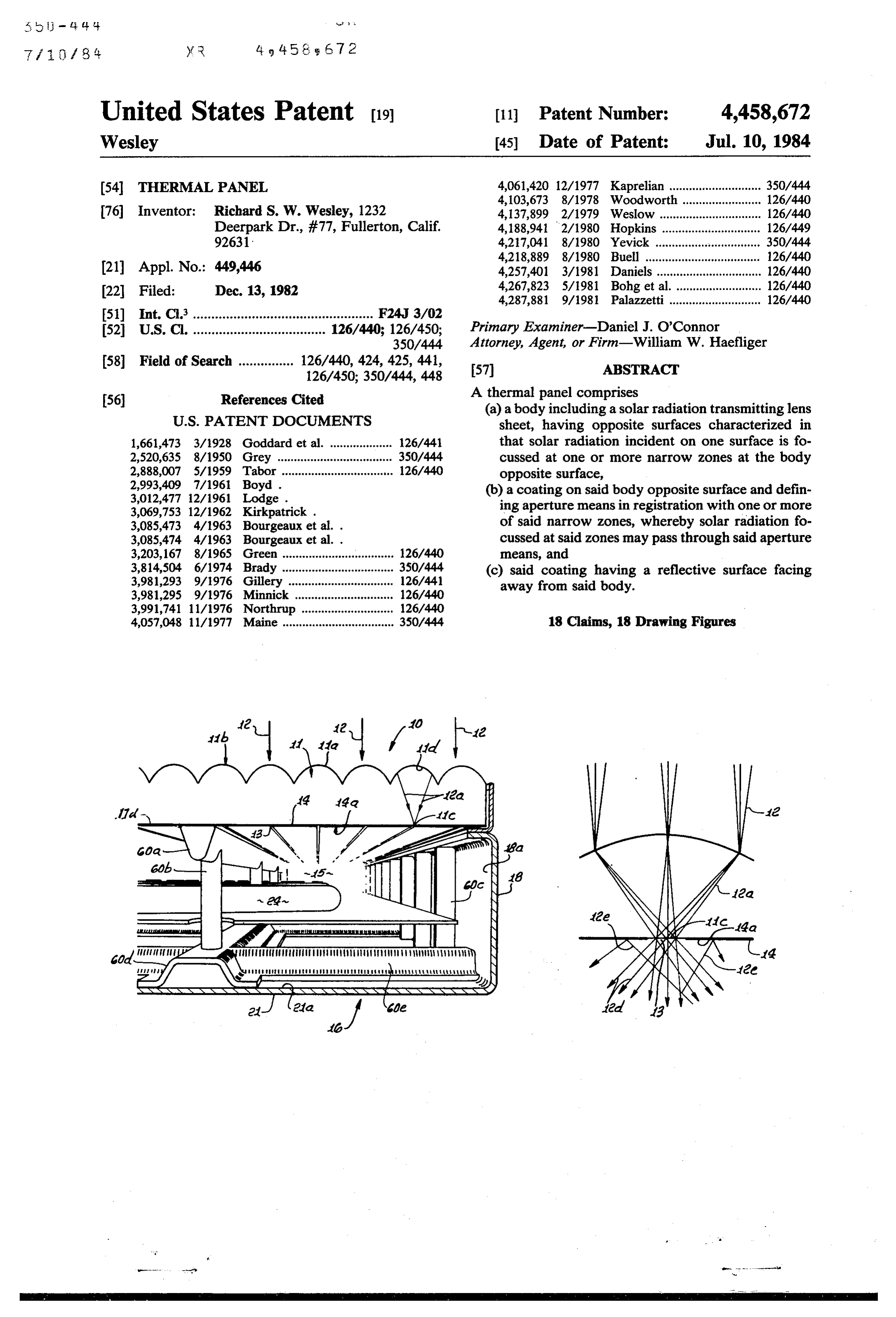
This invention relates generally to collection of solar FIG. 1 is a perspective taken in section through one form of apparatus embodying the invention;
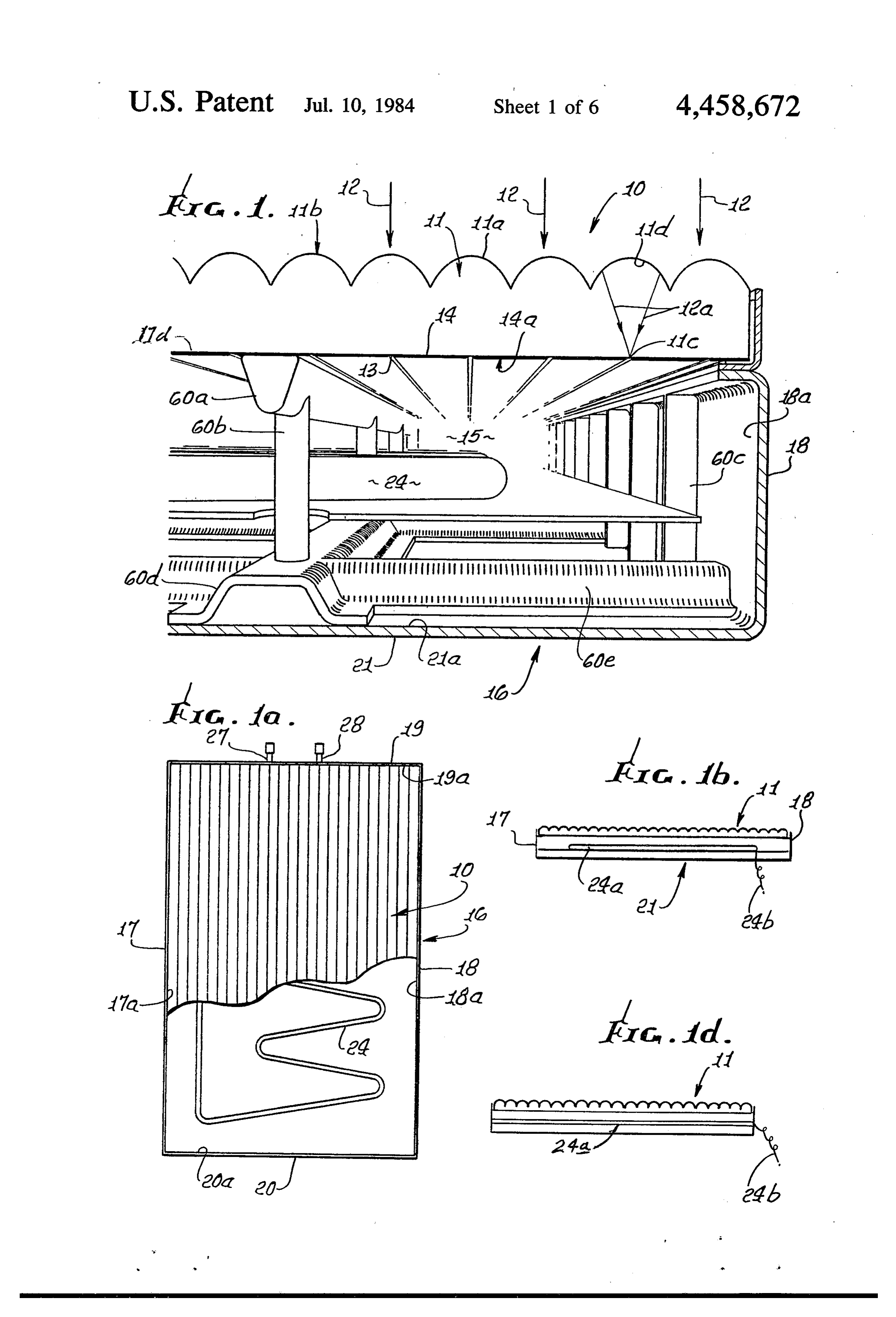
radiation, and more particularly concerns a thermal FIGS. 1a and 1b are smaller plan and end views of the panel and associated apparatus for efficiently retaining FIG. 1 apparatus;
heat in response to incidence of solar radiation. FIG. 1c is an elevation showing support and drive of Solar collectors are generally considered as efficient 10 the FIG. 1 apparatus in solar tracking mode; at collecting solar radiation. Unfortunately their ability FIG. 1d is a view like FIG. 1b, showing a modifica to collect solar radiation is often almost equalled by tion;
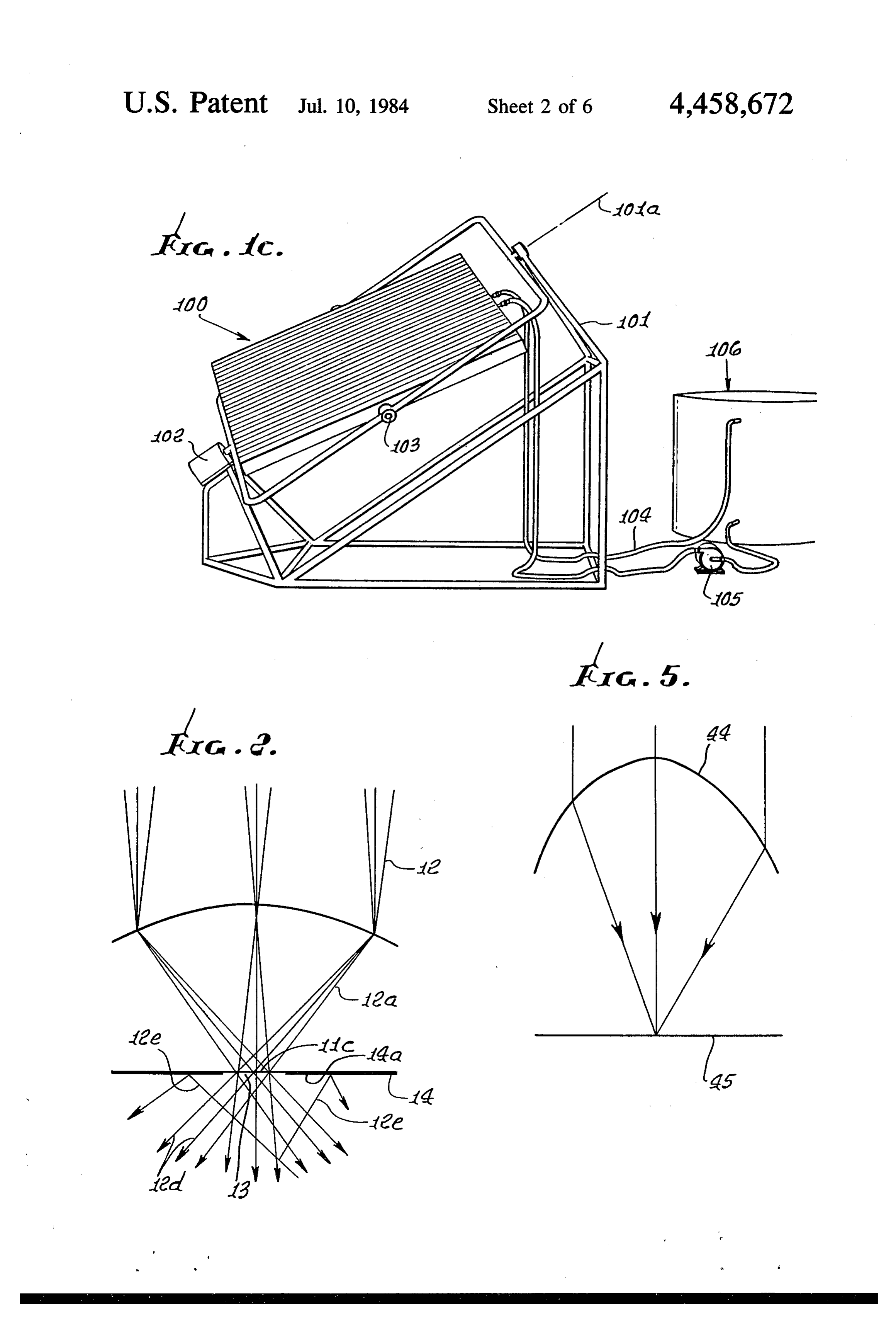
their ability to lose this energy, in the form of heat, back FIG. 2 is a diagrammatic view of solar ray transmis into the atmosphere. Such collectors do not satisfacto sion and focussing;
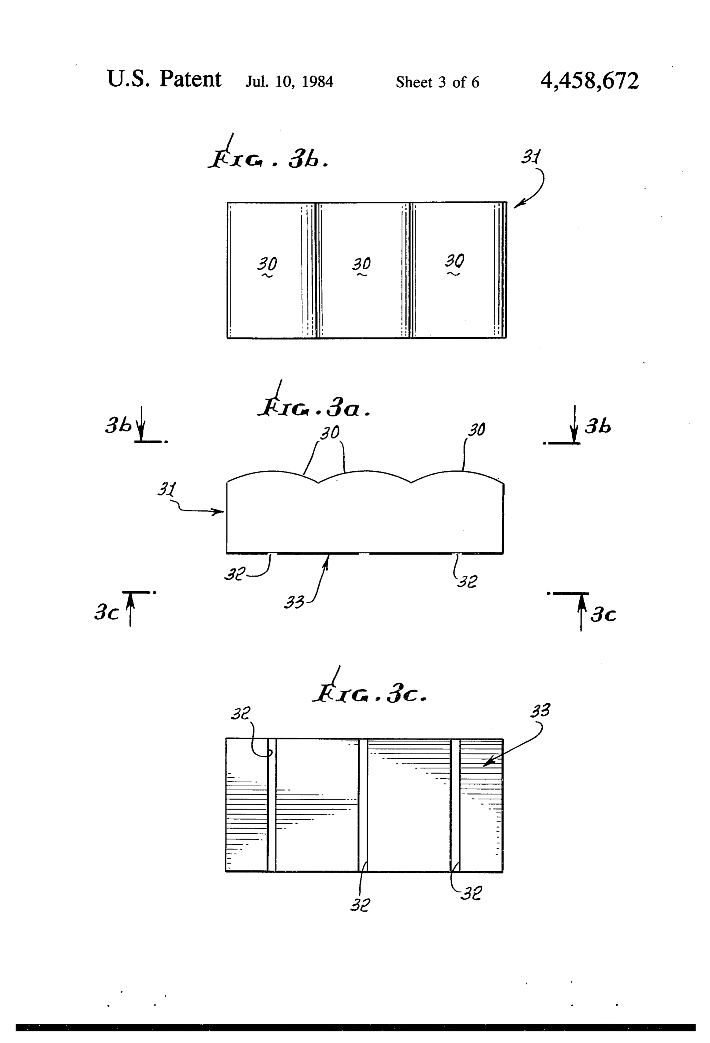
rily minimize the loss of heat from collection systems 15 FIG. 3a is a vertical section through a light transmis while at the same time offering little impedance to the sion sheet and reflective coating thereon; flow of solar radiation entering the collectors. FIG. 3b is a top plan view taken on lines 3b-3b of
FIG. 3c is a bottom plan view taken on lines 3c-3c of
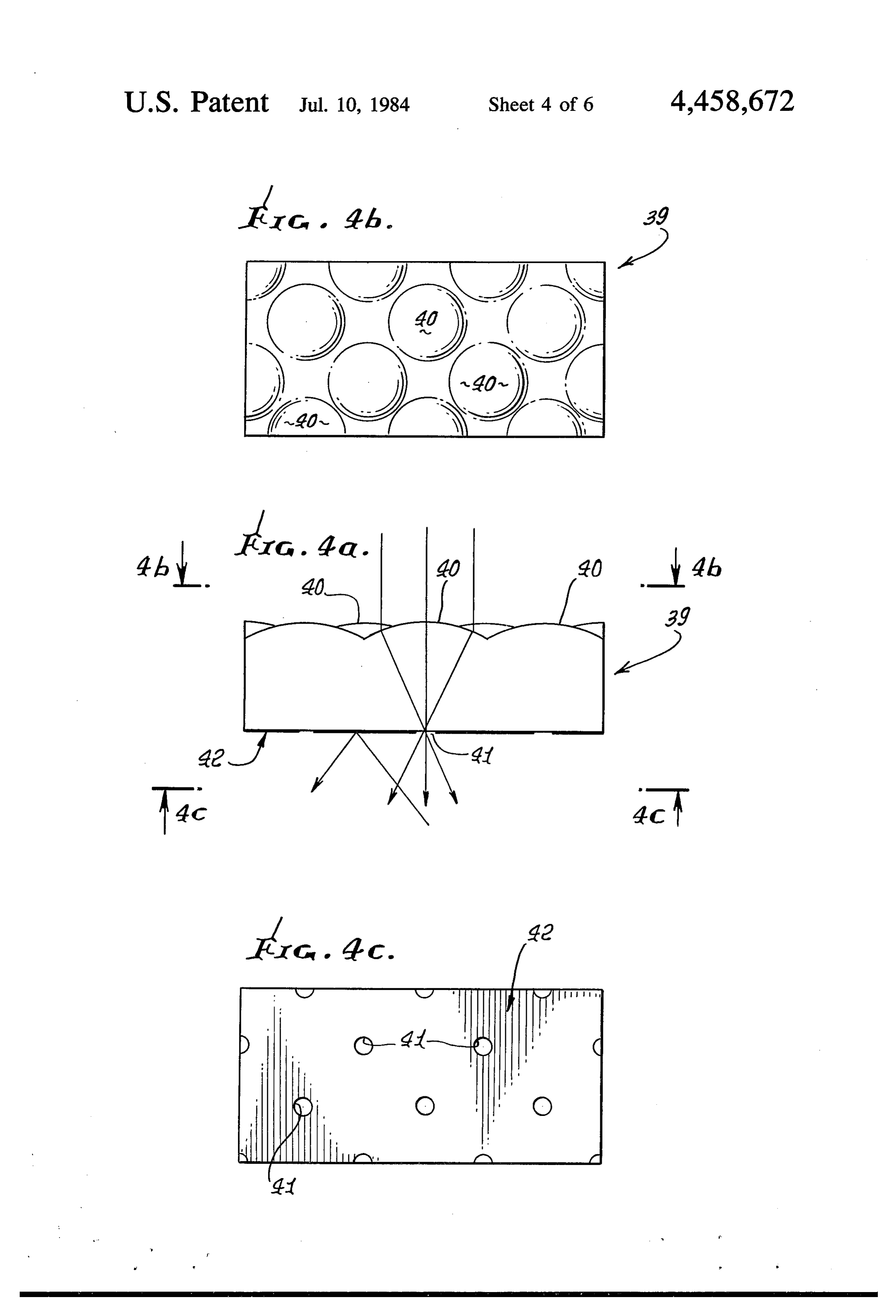
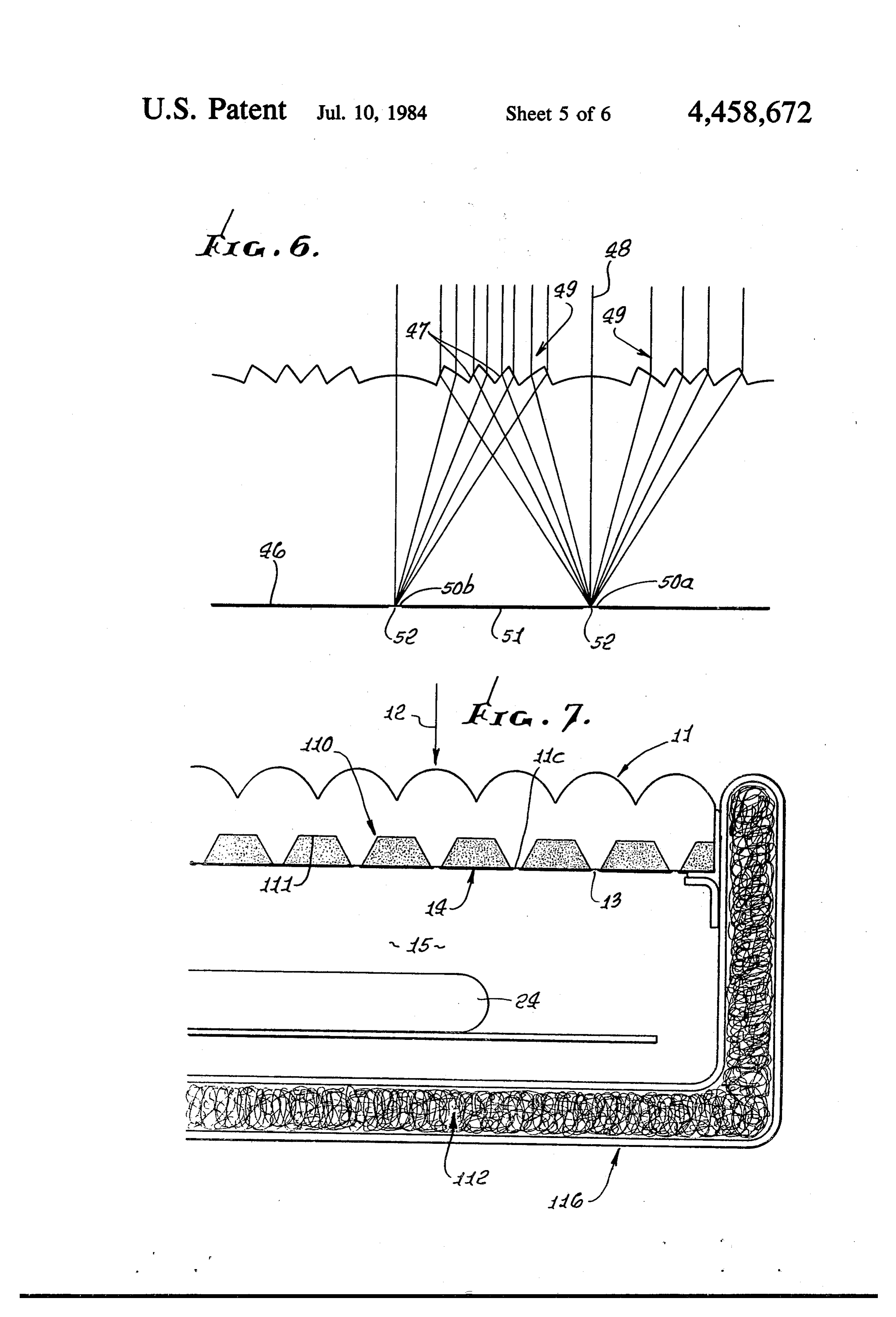
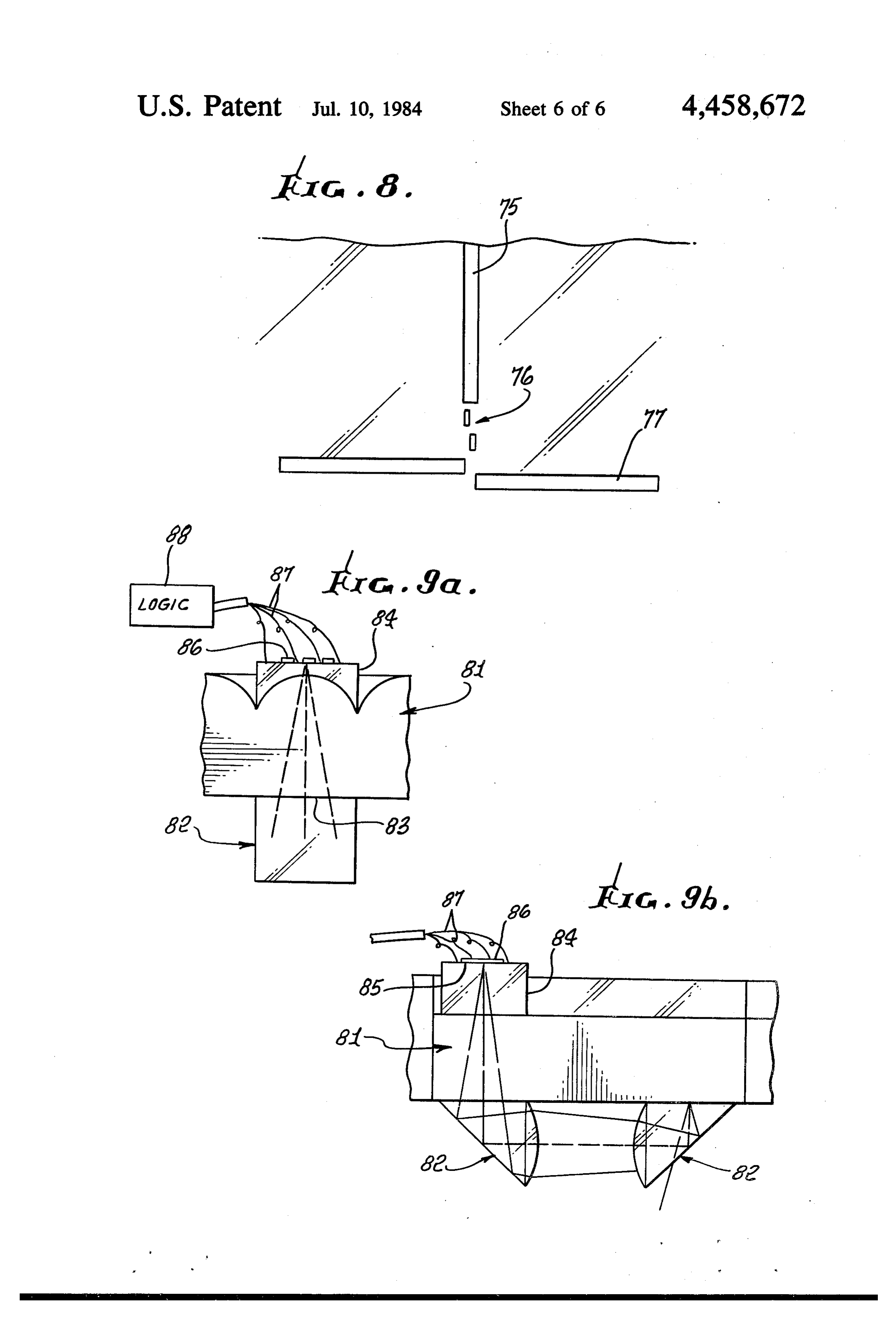
It is a major object of the invention to provide a solar 20 FIG. 3a, collector, including a thermal panel, characterized as FIG. 4a is a vertical section through a modified trans efficiently collecting solar radiation, and also entrap missive sheet, with reflective coating thereon; ping same, for energy transfer as desired. FIG. 4b is a top plan view taken on lines 4b-4b of In regard to the above, if a radiating body is placed FIG. 4a inside an evacuated container, and the walls of the con 25 FIG. 4c is a bottom plan view taken on lines 4c-4c of tainer are reflective, the loss of heat can be reduced to FIG. 4a an absolute minimum. The heat loss will be limited to FIG. 5 is a geometric diagram; the small amount of radiation still absorbed by the walls. FIG. 6 is a geometric diagram; Conversely, a lens transmits most of the light energy FIG. 7 is an elevation showing a modification. falling on it, while at the same time concentrating that 30 FIG. 8 is a plan view of an optical mask for an auto flow of energy into a smaller area. matic tracking device; and Consider a solar collector consisting of an evacuated tion, FIGS. 9a and 9b are end and side elevations, in sec chamber, with walls which are reflective. The upper showing an optical system to control solar track wall of the chamber, may for example, include a sheet 35 1ng.
made of a radiation transmissive material with, the top DETALED DESCRIPTION surface of the sheet covered by an array of lenses. The In FIG.1, body 10 includes a solar radiation transmis bottom surface of the sheet is located at the focal plane sive top sheet 11 (glass, plastic, etc.) having a top sur of these lenses. The collector then is rotated so that the face 11a which defines upwardly convex surfaces 11b.
transmissive lenses or panel is facing the sun. Most of 40 The the solar energy striking the lenses will pass through the Suchlatter define with sheet 11 a multiplicity of lenses. lenses focus incident radiation toward narrow panel, but will be concentrated in the very small area zones at or proximate the opposite surface. In FIGS. 1 where the sun's image appears on the second surface, and 2 see incident radiation 12, convergent at 12a towad i.e. bottom surface of the lens panel. If a reflective coat zones 11c. The narrow zones may for example be lo ing is located at all those points on the second surface 45 cated adjacent and in registration with aperture means where the sun's image does not appear, the coating will such as aperture 13 formed by a thin coating layer or reflect the radiation coming up from below and will layers 14 on the sheet opposite (lower) surface 11d, so entrap the energy within, but will not hamper the sun's that substantially all of the incident radiation is passed rays from passing through. through the narrow zones 11c and apertures 13 to the Basically, then, the invention is embodied in the com 50 space 15 at the underside of the body. Coating 14 typi bination that includes cally has a reflective surface 14a facing downwardly, (a) a body including a solar radiation transmitting lens i.e. away from the body 10, for radiation entrapment sheet, having opposite surfaces characterized in that purposes as will appear.
solar radiation incident on one surface is focussed at one The space 15 may with unusual advantage comprise or more narrow zones at the body opposite surface, 55 the evacuated interior of a chamber 16 wherein the (b) a coating on said body opposite surface and defin entering radiation becomes entrapped. To this end, the ing aperture means in registration with one or more of chamber 16 may include side walls 17 and 18, end walls said narrow zones, whereby solar radiation focussed at 19 and 20 and bottom wall 21, all of which have reflec said zones may pass through said aperture means, and tive surfaces 17a-21a facing the enclosed chamber inte (c) said coating having a reflective surface facing rior or space 15, as shown, whereby radiation is re away from said body. flected back and forth within that space to heat any The sunlight entering the collector is typically made object therein. Each of the walls or reflection surfaces to fall on a device that converts this entrapped radiant 17a-21a and coating 14 may consist of a thin layer of energy into a suitable or usable form, such as heat or vapor deposited metal such as aluminum or silver, and electricity. The heated medium or product is removable 65 having a highly reflective surface exposed toward through the walls of the solar collector. spaced 15.
These and other objects and advantages of the inven Also shown in FIG. 1 is a heat exchanger duct 24 tion, as well as the details of an illustrative embodiment, extending lengthwise within the space 15, to pass fluid
Page 9
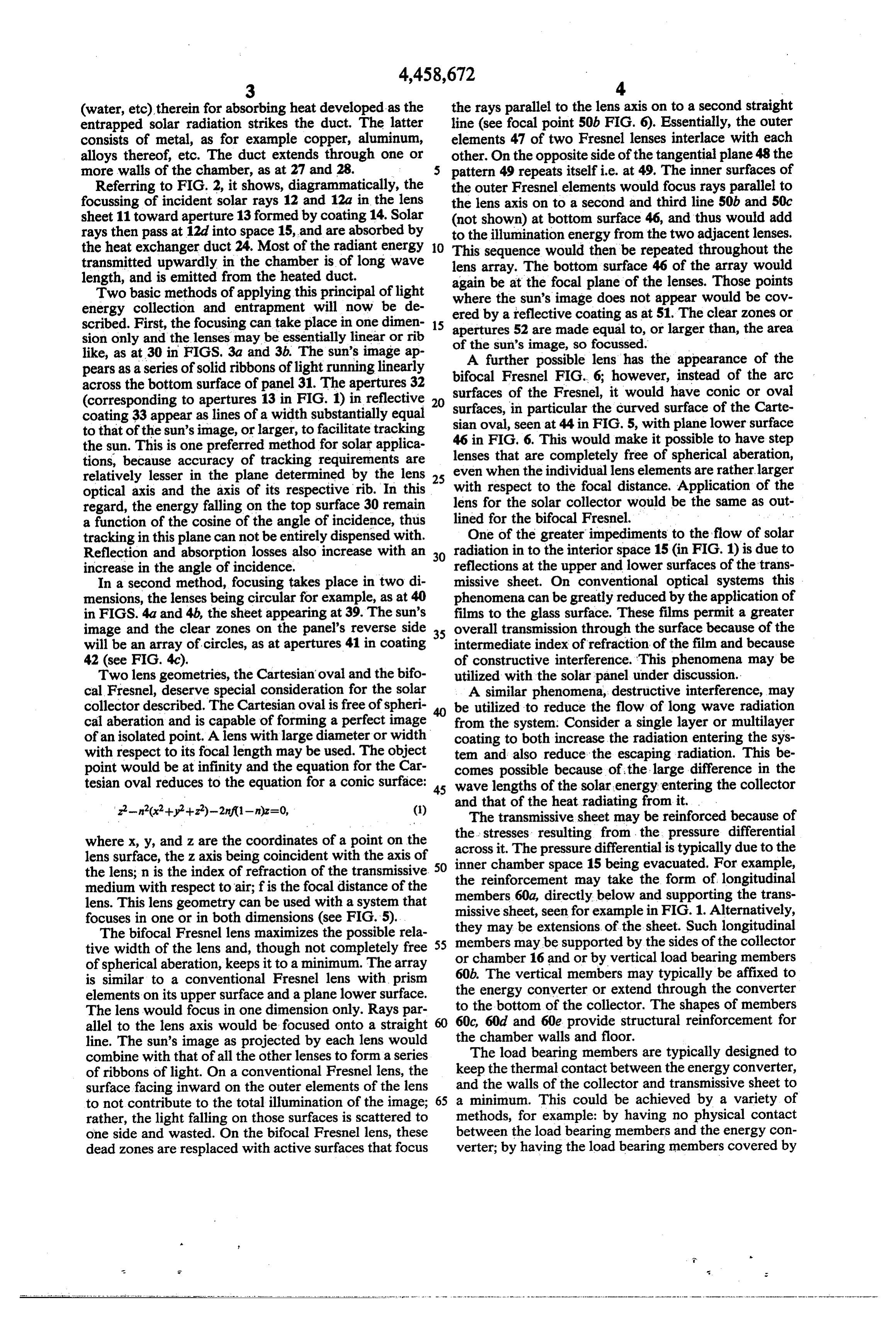
(water, etc), therein for absorbing heat developed as the the rays parallel to the lens axis on to a second straight entrapped solar radiation strikes the duct. The latter line (see focal point 50b FIG. 6). Essentially, the outer consists of metal, as for example copper, aluminum, elements 47 of two Fresnel lenses interlace with each alloys thereof, etc. The duct extends through one or other. On the opposite side of the tangential plane 48 the more walls of the chamber, as at 27 and 28. pattern 49 repeats itself i.e. at 49. The inner surfaces of Referring to FIG. 2, it shows, diagrammatically, the the outer Fresnel elements would focus rays parallel to focussing of incident solar rays 12 and 12a in the lens the lens axis on to a second and third line 50b and 50c sheet 11 toward aperture 13 formed by coating 14. Solar (not shown) at bottom surface 46, and thus would add rays then pass at 12d into space 15, and are absorbed by to the illumination energy from the two adjacent lenses. the heat exchanger duct 24. Most of the radiant energy 10 This sequence would then be repeated throughout the transmitted upwardly in the chamber is of long wave lens array. The bottom surface 46 of the array would length, and is emitted from the heated duct.
Two basic methods of applying this principal of light again be at the focal plane of the lenses. Those points energy collection and entrapment will now be de ered bythe where
sun's image does not appear would be cov reflective coating as at 51. The clear zones or scribed. First, the focusing can take place in one dimen 15 apertures 52 are made equal to, or larger than, the area sion only and the lenses may be essentially linear or rib of the sun's image, so focussed.
like, as at 30 in FIGS. 3a and 3b. The sun's image ap A further possible lens has the appearance of the pears as a series of solid ribbons of light running linearly bifocal across the bottom surface of panel 31. The apertures 32 surfacesFresnel FIG. 6; however, instead of the arc of the Fresnel, it would have conic or oval (corresponding to apertures 13 in FIG. 1) in reflective 20 coating 33 appear as lines of a width substantially equal surfaces, in particular the curved surface of the Carte sian oval, seen at 44 in FIG. 5, with plane lower surface to that of the sun's image, or larger, to facilitate tracking 46 in FIG. 6. This would make it possible to have step the sun. This is one preferred method for solar applica lenses that are completely free of spherical aberation, tions, because accuracy of tracking requirements are relatively lesser in the plane determined by the lens 25 even when the individual lens elements are rather larger optical axis and the axis of its respective rib. In this with respect to the focal distance. Application of the regard, the energy falling on the top surface 30 remain lens for the solar collector would be the same as out a function of the cosine of the angle of incidence, thus lined for the bifocal Fresnel. " .. tracking in this plane cannot be entirely dispensed with. One of the greater impediments to the flow of solar Reflection and absorption losses also increase with an 30 radiation in to the interior space 15 (in FIG. 1) is due to increase in the angle of incidence. reflections at the upper and lower surfaces of the trans In a second method, focusing takes place in two di missive sheet. On conventional optical systems this mensions, the lenses being circular for example, as at 40 phenomena can be greatly reduced by the application of in FIGS. 4a and 4b, the sheet appearing at 39. The sun's films to the glass surface. These films permit a greater image and the clear zones on the panel's reverse side 35 overall transmission through the surface because of the will be an array of circles, as at apertures 41 in coating intermediate index of refraction of the film and because 42 (see FIG. 4c). of constructive interference. This phenomena may be Two lens geometries, the Cartesian oval and the bifo utilized with the solar panel under discussion. cal Fresnel, deserve special consideration for the solar A similar phenomena, destructive interference, may collector described. The Cartesian oval is free of spheri be utilized to reduce the flow of long wave radiation cal aberation and is capable of forming a perfect image from the system. Consider a single layer or multilayer of an isolated point. A lens with large diameter or width coating to both increase the radiation entering the sys with respect to its focal length may be used. The object tem and also reduce the escaping radiation. This be point would be at infinity and the equation for the Car comes possible because of the large difference in the tesian oval reduces to the equation for a conic surface: 45 wave lengths of the solar energy entering the collector z-n(x+y+z)-2nf(1-n)z=0, (1) and that of the heat radiating from it. . The transmissive sheet may be reinforced because of where x, y, and z are the coordinates of a point on the acrossstresses the resulting from the pressure differential lens surface, the z axis being coincident with the axis of 50 inner chamberpressure it. The space differential is typically due to the 15 being evacuated. For example, the lens; n is the index of refraction of the transmissive medium with respect to air; fis the focal distance of the the reinforcement may take the form of longitudinal members 60a, directly below and supporting the trans lens. This lens geometry can be used with a system that missive sheet, seen for example in FIG.1. Alternatively, focuses in one or in both dimensions (see FIG. 5).
The bifocal Fresnel lens maximizes the possible rela 55 they may be extensions of the sheet. Such longitudinal tive width of the lens and, though not completely free members may be supported by the sides of the collector of spherical aberation, keeps it to a minimum. The array or chamber 16 and or by vertical load bearing members is similar to a conventional Fresnel lens with prism 60b. energy The vertical members may typically be affixed to elements on its upper surface and a plane lower surface. the converter or extend through the converter The lens would focus in one dimension only. Rays par to the bottom of the collector. The shapes of members allel to the lens axis would be focused onto a straight 60 the60c, 60d and 60e provide structural reinforcement for line. The sun's image as projected by each lens would chamber walls and floor.
combine with that of all the other lenses to form a series The load bearing members are typically designed to of ribbons of light. On a conventional Fresnel lens, the and keep the thermal contact between the energy converter, surface facing inward on the outer elements of the lens the walls of the collector and transmissive sheet to to not contribute to the total illumination of the image; 65 a minimum. This could be achieved by a variety of rather, the light falling on those surfaces is scattered to methods, for example: by having no physical contact one side and wasted. On the bifocal Fresnel lens, these between the load bearing members and the energy con dead zones are resplaced with active surfaces that focus verter; by having the load bearing members covered by
Page 10
a reflective surface; by designing the geometry of the underside of the transmissive sheet to permit easier load bearing member such that the surface of the mem viewing through the side of the collector. This can be ber exposed to thermal radiation is minimal; by con improved upon by frosting that portion of the clear structing the load bearing members using materials with zone which is viewed, thereby, making it easier to lo low thermal conductivity; and by using insulating mate cate the exact position of the sun's image. rials at key points of contact. A lens or lenses can be added to the optical system A somewhat different technique for countering the and placed between the prism (mirror) and window (see stresses and distortions induced by the evacuated cham 82a FIG.9b). If one surface of the window is the frosted ber is to construct the transmissive sheet with a bowed element, then viewing can be improved by having the shape. When the lower surface of the sheet is exposed to 10 lens project the sun's image on to that surface; other vacuum, the atmospheric pressure on the upper surface wise, the lens can be used simply to magnify the sun's would force the sheet into the desired planer shape. image.
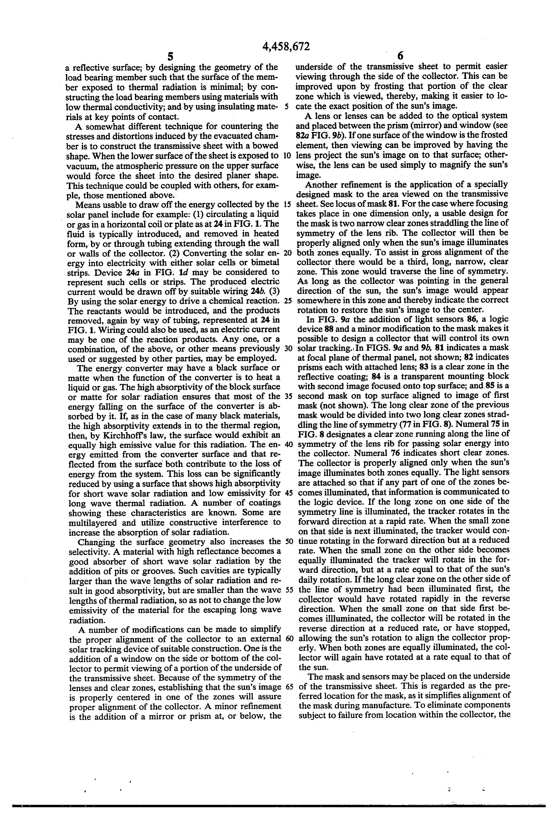
This technique could be coupled with others, for exam Another refinement is the application of a specially ple, those mentioned above. designed mask to the area viewed on the transmissive Means usable to draw off the energy collected by the 15 sheet. Seelocus of mask 81. For the case where focusing solar panel include for example: (1) circulating a liquid takes place in one dimension only, a usable design for or gas in a horizontal coil or plate as at 24 in FIG.1. The the mask is two narrow clear zones straddling the line of fluid is typically introduced, and removed in heated symmetry of the lens rib. The collector will then be form, by or through tubing extending through the wall properly aligned only when the sun's image illuminates or walls of the collector. (2) Converting the solar en 20 both zones equally. To assist in gross alignment of the ergy into electricity with either solar cells or bimetal collector there would be a third, long, narrow, clear strips. Device 24a in FIG. 1d may be considered to zone. This zone would traverse the line of symmetry. represent such cells or strips. The produced electric As long as the collector was pointing in the general current would be drawn off by suitable wiring 24b. (3) direction of the sun, the sun's image would appear By using the solar energy to drive a chemical reaction. 25 somewhere in this zone and thereby indicate the correct The reactants would be introduced, and the products rotation to restore the sun's image to the center. removed, again by way of tubing, represented at 24 in In FIG. 9a the addition of light sensors 86, a logic FIG. 1. Wiring could also be used, as an electric current device 88 and a minor modification to the mask makes it may be one of the reaction products. Any one, or a possible to design a collector that will control its own combination, of the above, or other means previously 30 solar tracking. In FIGS. 9a and 9b, 81 indicates a mask used or suggested by other parties, may be employed. at focal plane of thermal panel, not shown; 82 indicates The energy converter may have a black surface or prisms each with attached lens; 83 is a clear zone in the matte when the function of the converter is to heat a reflective coating; 84 is a transparent mounting block liquid or gas. The high absorptivity of the block surface with second image focused onto top surface; and 85 is a or matte for solar radiation ensures that most of the 35 second mask on top surface aligned to image of first energy falling on the surface of the converter is ab mask (not shown). The long clear zone of the previous sorbed by it. If, as in the case of many black materials, mask would be divided into two long clear zones strad the high absorptivity extends in to the thermal region, dling the line of symmetry (77 in FIG. 8). Numeral 75 in then, by Kirchhoff's law, the surface would exhibit an FIG. 8 designates a clear zone running along the line of equally high emissive value for this radiation. The en 40 symmetry of the lens rib for passing solar energy into ergy emitted from the converter surface and that re the collector. Numeral 76 indicates short clear zones. flected from the surface both contribute to the loss of The collector is properly aligned only when the sun's energy from the system. This loss can be significantly image illuminates both zones equally. The light sensors reduced by using a surface that shows high absorptivity are attached so that if any part of one of the zones be for short wave solar radiation and low emissivity for 45 comes illuminated, that information is communicated to long wave thermal radiation. A number of coatings the logic device. If the long zone on one side of the showing these characteristics are known. Some are symmetry line is illuminated, the tracker. rotates in the multilayered and utilize constructive interference to forward direction at a rapid rate. When the small zone increase the absorption of solar radiation. on that side is next illuminated, the tracker would con Changing the surface geometry also increases the 50 tinue rotating in the forward direction but at a reduced selectivity. A material with high reflectance becomes a rate. When the small zone on the other side becomes good absorber of short wave solar radiation by the equally illuminated the tracker will rotate in the for addition of pits or grooves. Such cavities are typically ward direction, but at a rate equal to that of the sun's larger than the wave lengths of solar radiation and re daily rotation. If the long clear zone on the other side of sult in good absorptivity, but are smaller than the wave 55 the line of symmetry had been illuminated first, the lengths of thermal radiation, so as not to change the low collector would have rotated rapidly in the reverse emissivity of the material for the escaping long wave direction. When the small zone on that side first be radiation. comes illuminated, the collector will be rotated in the A number of modifications can be made to simplify reverse direction at a reduced rate, or have stopped, the proper alignment of the collector to an external allowing the sun's rotation to align the collector prop solar tracking device of suitable construction. One is the erly. When both zones are equally illuminated, the col addition of a window on the side or bottom of the col lector will again have rotated at a rate equal to that of lector to permit viewing of a portion of the underside of the sun.
the transmissive sheet. Because of the symmetry of the The mask and sensors may be placed on the underside lenses and clear zones, establishing that the sun's image 65 of the transmissive sheet. This is regarded as the pre is properly centered in one of the zones will assure ferred location for the mask, as it simplifies alignment of proper alignment of the collector. A minor refinement the mask during manufacture. To eliminate components is the addition of a mirror or prism at, or below, the subject to failure from location within the collector, the
Page 11
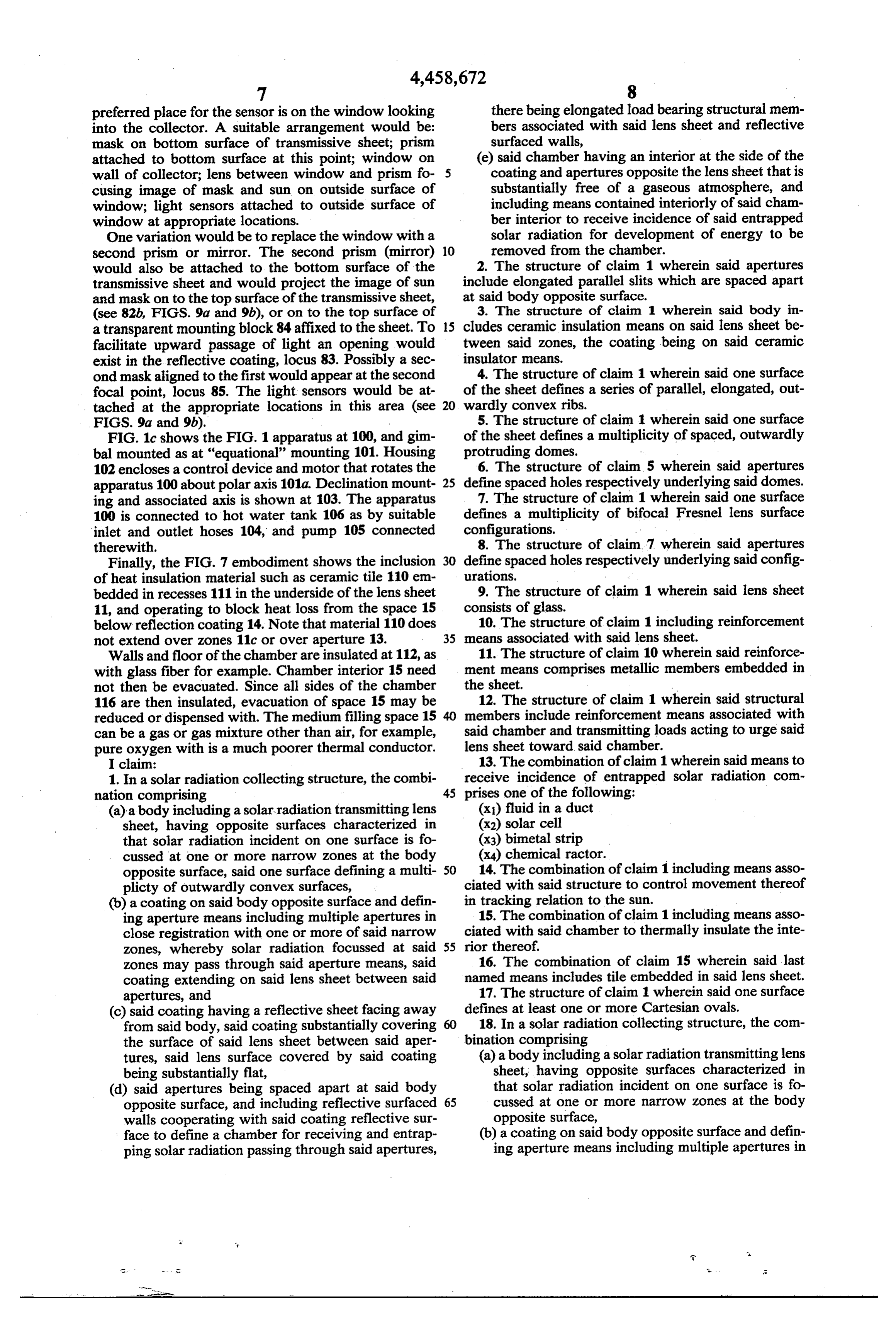
preferred place for the sensor is on the window looking there being elongated load bearing structural mem into the collector. A suitable arrangement would be: bers associated with said lens sheet and reflective mask on bottom surface of transmissive sheet; prism surfaced walls, attached to bottom surface at this point; window on (e) said chamber having an interior at the side of the wall of collector; lens between window and prism fo 5 coating and apertures opposite the lens sheet that is cusing image of mask and sun on outside surface of substantially free of a gaseous atmosphere, and window; light sensors attached to outside surface of including means contained interiorly of said cham window at appropriate locations. ber interior to receive incidence of said entrapped One variation would be to replace the window with a solar radiation for development of energy to be second prism or mirror. The second prism (mirror) 10 removed from the chamber. would also be attached to the bottom surface of the 2. The structure of claim 1 wherein said apertures transmissive sheet and would project the image of sun include elongated parallel slits which are spaced apart and mask on to the top surface of the transmissive sheet, at said body opposite surface.
(see 82b, FIGS. 9a and 9b), or on to the top surface of 3. The structure of claim 1 wherein said body in a transparent mounting block 84 affixed to the sheet. To 15 cludes ceramic insulation means on said lens sheet be facilitate upward passage of light an opening would tween said zones, the coating being on said ceramic exist in the reflective coating, locus 83. Possibly a sec insulator means.
ond mask aligned to the first would appear at the second 4. The structure of claim 1 wherein said one surface focal point, locus 85. The light sensors would be at of the sheet defines a series of parallel, elongated, out tached at the appropriate locations in this area (see 20 wardly convex ribs.
FIGS. 9a and 9b). 5. The structure of claim 1 wherein said one surface FIG. 1c shows the FIG. 1 apparatus at 100, and gim of the sheet defines a multiplicity of spaced, outwardly bal mounted as at "equational' mounting 101. Housing protruding domes.
102 encloses a control device and motor that rotates the 6. The structure of claim 5 wherein said apertures apparatus 100 about polar axis 101a. Declination mount 25 define spaced holes respectively underlying said domes. ing and associated axis is shown at 103. The apparatus 7. The structure of claim 1 wherein said one surface 100 is connected to hot water tank 106 as by suitable defines a multiplicity of bifocal Fresnel lens surface inlet and outlet hoses 104, and pump 105 connected configurations.
therewith. 8. The structure of claim. 7 wherein said apertures Finally, the FIG. 7 embodiment shows the inclusion 30 define spaced holes respectively underlying said config of heat insulation material such as ceramic tile 110 em urations.
bedded in recesses 111 in the underside of the lens sheet 9. The structure of claim 1 wherein said lens sheet 11, and operating to block heat loss from the space 15 consists of glass.
below reflection coating 14. Note that material 110 does 10. The structure of claim 1 including reinforcement not extend over zones 11c or over aperture 13. 35 means associated with said lens sheet. Walls and floor of the chamber are insulated at 112, as 11. The structure of claim 10 wherein said reinforce with glass fiber for example. Chamber interior 15 need ment means comprises metallic members embedded in not then be evacuated. Since all sides of the chamber the sheet.
116 are then insulated, evacuation of space 15 may be 12. The structure of claim 1 wherein said structural reduced or dispensed with. The medium filling space 15 members include reinforcement means associated with can be a gas or gas mixture other than air, for example, said chamber and transmitting loads acting to urge said pure oxygen with is a much poorer thermal conductor. lens sheet toward said chamber. I claim: 13. The combination of claim 1 wherein said means to 1. In a solar radiation collecting structure, the combi receive incidence of entrapped solar radiation com nation comprising 45 prises one of the following: (a) a body including a solar radiation transmitting lens (x) fluid in a duct sheet, having opposite surfaces characterized in (x2) solar cell that solar radiation incident on one surface is fo (x3) bimetal strip cussed at one or more narrow zones at the body (x4) chemical ractor.
opposite surface, said one surface defining a multi 50 14. The combination of claim 1 including means asso plicty of outwardly convex surfaces, ciated with said structure to control movement thereof (b) a coating on said body opposite surface and defin in tracking relation to the sun.
ing aperture means including multiple apertures in 15. The combination of claim 1 including means asso close registration with one or more of said narrow ciated with said chamber to thermally insulate the inte zones, whereby solar radiation focussed at said 55 rior thereof.
Zones may pass through said aperture means, said 16. The combination of claim 15 wherein said last coating extending on said lens sheet between said named means includes tile embedded in said lens sheet. apertures, and 17. The structure of claim 1 wherein said one surface (c) said coating having a reflective sheet facing away defines at least one or more Cartesian ovals. from said body, said coating substantially covering 18. In a solar radiation collecting structure, the com the surface of said lens sheet between said aper bination comprising tures, said lens surface covered by said coating (a) a body including a solar radiation transmitting lens being substantially flat, sheet, having opposite surfaces characterized in (d) said apertures being spaced apart at said body that solar radiation incident on one surface is fo opposite surface, and including reflective surfaced 65 cussed at one or more narrow zones at the body walls cooperating with said coating reflective sur opposite surface, face to define a chamber for receiving and entrap (b) a coating on said body opposite surface and defin ping solar radiation passing through said apertures, ing aperture means including multiple apertures in
e s
Page 12
close registration with one or more of said narrow erating with said coating reflective surface to de zones, whereby solar radiation focussed at said fine a chamber for receiving and entrapping solar zones may pass through said aperture means, said radiation passing through said apertures, there coating extending on said lens sheet between said being reinforcement means associated with said apertures, and lens sheet comprising at least one longitudinally (c) said coating having a reflective surface facing elongated upper member extending directly below away from said body, said coating substantially and in supporting relation with the lens sheet, a covering the surface of said lens sheet between said load bearing upright support member for said apertures, said lens sheet surface being substantially upper member located interiorly of the chamber, flat, 10 an elongated lower support member for said up (d) said apertures defining elongated parallel slits right member, and multiple side support means at which are spaced apart at said body opposite sur at least one side of the chamber.
face, and including reflective surfaced walls coop
Provenance
- Collection
- Cited prior art
- Original PDF
- patentimages.storage.googleapis.com →
- Filed
- 1982-12-13
- Pages
- 12
- Method
- pdftotext (the PDF's own text layer) + pdftoppm 300dpi page scans
- Source
- Google Patents bibliographic record
- Granted
- 1984-07-10
- Inventors
- Richard S. W. Wesley
- Transcribed from
- patentimages.storage.googleapis.com →