patent · US4380970
Combustion engines
26 April 1983
Page 1 — bibliographic record
United States Patent (19) 11) 4,380,970 Davis (45) Apr. 26, 1983 (54) COMBUSTION ENGINES 4,037,568 7/1977 Sugimoto .......................... 23/25 B 76) Inventor: Roy A. Davis, 43 Glendower St., FOREIGN PATENT DOCUMENTS Perth, Australia, 6000 52-2 1528 2/1977 Japan .......................... 123/DG, 12 21 Appl. No.: 248,499 Primary Examiner-Wendell E. Burns 22 Filed: Mar. 27, 1981 Attorney, Agent, or Firm-Dennison, Meserole, Pollack & Scheiner
Related U.S. Application Data 57 ABSTRACT 63 Continuation-in-part of Ser. No. 75,003, Sep. 12, 1979, The invention provides an alternative fuel for internal abandoned.
combustion engines in which the exhaust heat is used to 30 Foreign Application Priority Data thermally dissociate water to its constituent gases hy Aug. 1, 1979 AU Australia .............................. PD988 drogen and oxygen. The hydrogen and oxygen so pro duced is introduced into the combustion chamber of the 51) Int, Cl. ...................... F02B 43/08; F02D 19/00; engine to at least partially replace the conventional fuel. FO2M 25/00 In a preferred embodiment of the invention, water is 52 U.S. Cl. ...................................... 123/3; 123/25 B; dissociated into hydrogen and oxygen in a dissociation 123/DIG. 12; 123/1 A; 123/25 R chamber in the form of a transition tube containing a (58) Field of Search .......... 123/DIG. 12, 25 B, 25 D, spirally wound ribbon arranged to urge water in the 123/25 P, 3, 1 A, 25 R transition tube outwardly into contact with walls of the 56 References Cited transition tube, said walls being heated by exhaust gases
4,030,453 6/1977 Schreiber ..................., 123/DIG. 12 10 Claims, 7 Drawing Figures
Page 2
Drawing sheet — no readable text.
Page 3
Drawing sheet — no readable text.
Page 4
Drawing sheet — no readable text.
Page 5
Drawing sheet — no readable text.
Page 6
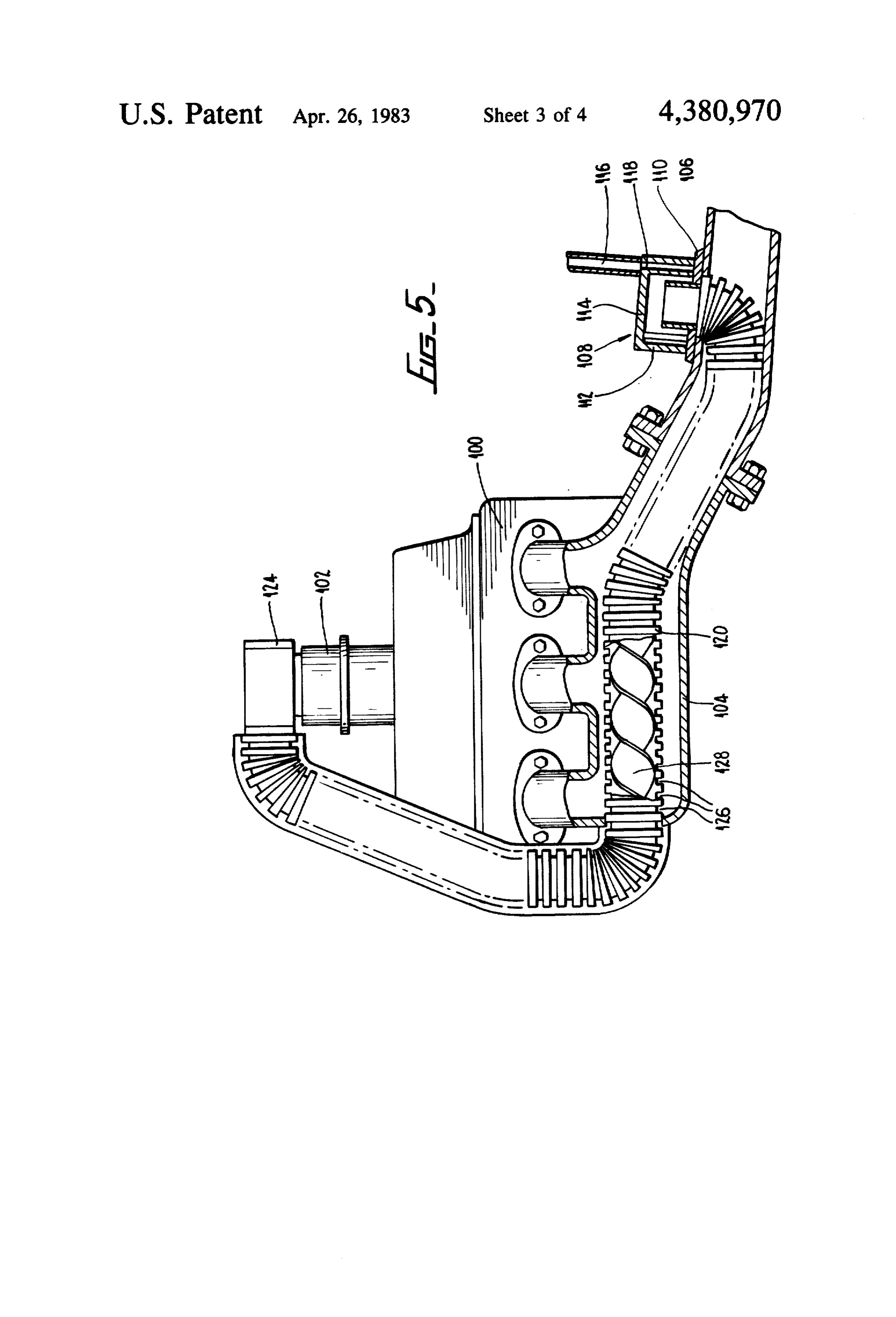
FIG. 5 is a schematic side elevation of an internal
COMBUSTON ENGINES combustion engine provided with a modified and im proved chamber in accordance with the present inven
This application is a continuation-in-part of now tion;
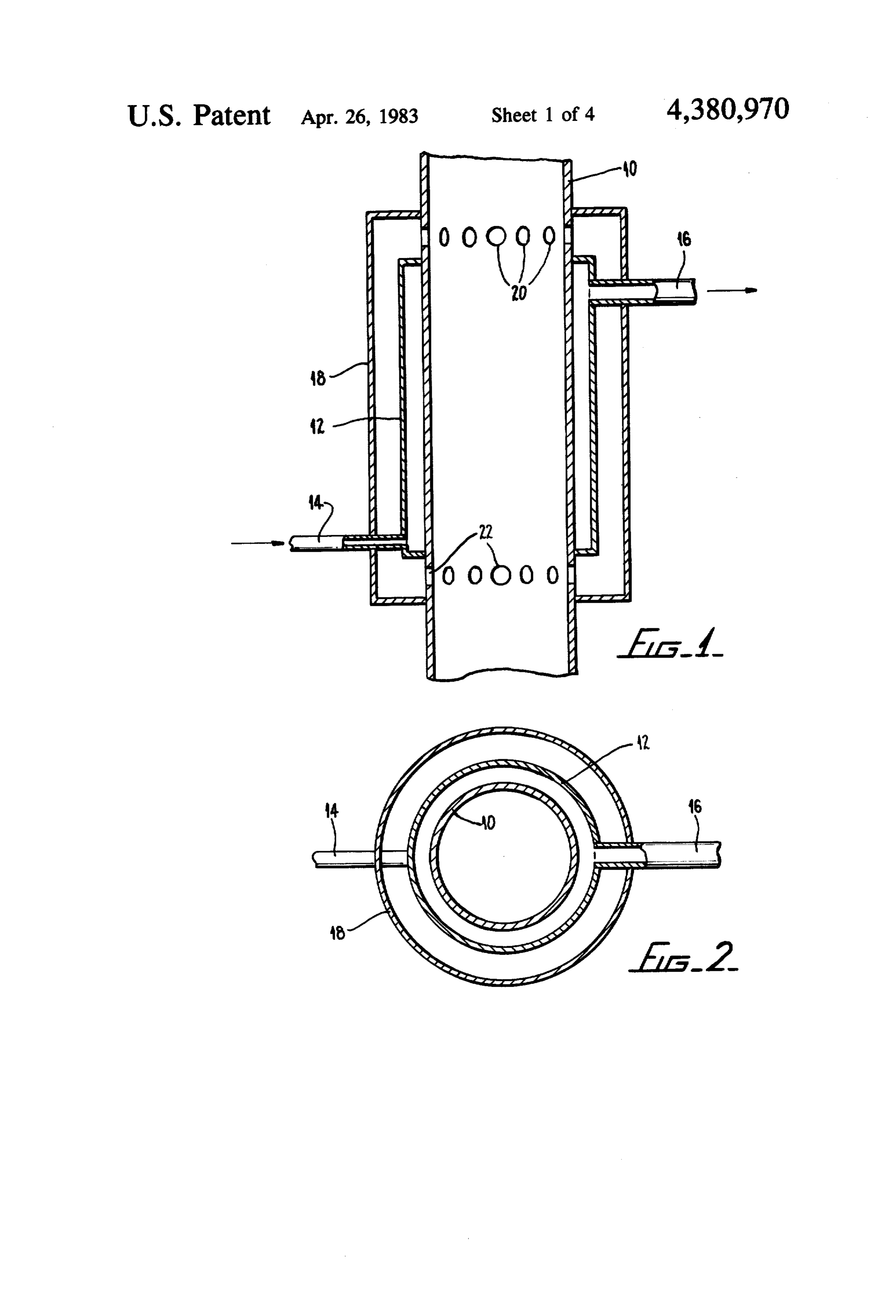
abandoned application No. 75,003 filed Sept. 12, 1979 in FIG. 6 is a schematic side elevation of an air induc the name of ROY A. DAVIS. tion system for a carburettor which system is provided The present invention relates to internal combustion with a sound projector; and engines. Internal combustion engines including four FIG. 7 is a plan view of the system of FIG. 6. stroke and two stroke piston engines, rotary engines, In FIGS. 1 and 2, there is shown an exhaust pipe 10 diesel engines, jet engines and gas turbines are for the 10 of a four stroke internal combustion engine of a typical most part fuelled by liquid fuels obtained from petro road vehicle. An annular chamber 12 is mounted about leum. In recent years there has been increasing concern the exhaust pipe 12. The chamber 12 comprises inlet that the available reserves of petroleum are limited. means 14 and an outlet means 16.
With present consumption rates the world could face A container 18 is mounted to the exhaust pipe 10 and mounting difficulties in meeting the demand for liquid 5 surrounds the chamber 12. The container 18 is in fluid fuels in the years to come. There have been many pro communication with the exhaust pipe 10 through holes posals for alternative fuels but so far no fully satisfac 20 and 22. Typically, the chamber 12 and container 18 tory alternative to liquid petroleum based products has are welded to the exhaust pipe 10. been found.
It has now been discovered that an internal combus 20 In use, while the engine is in operation, exhaust gases pass through tion engine can be fuelled at least in part by an alterna thereof to become the exhaust pipe 10 and cause the wall tive fuel which utilizes the waste heat of the exhaust heated. A minor proportion of ex gases of the internal combustion engine, haust gases also pass through the holes 20 into the con In accordance with the present invention there is tainer 18. These exhaust gases heat the walls of the provided a method of operating an internal combustion 25 container 18 while passing therethrough and return to engine comprising inlet means, a combustion chamber the exhaust pipe 10 through the holes 22. Thus, the and exhaust means, which method comprises introduc walls of the chamber 12, that is the common walls with ing a combustible gaseous composition into the combus the exhaust pipe 10 and container 18 become heated. tion chamber through the inlet means thereof, combust Water is introduced into the chamber 12 through the ing the combustible composition in the combustion 30 inlet means 14. The water so introduced is heated by the chamber to provide a driving force for the engine, and walls of the chamber 12 and thermally dissociated into exhausting the combusted composition from the com its constituent gases hydrogen and oxygen. The outlet bustion chamber through the exhaust means, wherein ventional means 16 is in communication with the choke of a con the combusted material is caused to heat water to a carburettor.
temperature sufficient to thermally dissociate the water 35 In conventional manner a piston reciprocates within a into its constituent gases hydrogen and oxygen, and cylinder of the four stroke engine. On every other down hydrogen and oxygen so produced is introduced into stroke of the piston an inlet valve is opened to admit air the combustion chamber to form at least part of said and fuel mixture from the carburettor into the cylinder. combustible composition. Normally, the fuel is petrol which is supplied in liquid In accordance with the present invention there is also 40 form to the carburettor. Petrol vapour is induced into provided an internal combustion engine comprising the air stream flowing through the choke of the carbu inlet means, a combustion chamber and exhaust means, rettor. The petrol enters the air stream from a pilot jet a dissociation chamber in heat communication with the and a main jet. The pilot jet is used when the engine is exhaust means, inlet means for the dissociation chamber idling and the main jet is used to supply fuel when the and outlet means for the dissociation chamber, means 45 vehicle is in motion.
for introducing water to the dissociation chamber With the apparatus of the present invention the main through the inlet means thereof, and means for intro jet can be closed off so that no petrol enters the air ducing gases into the inlet means of the combustion stream through the main jet. Thus, when the inlet valve chamber from the dissociation chamber through the of the engine is open and the piston is travelling down outlet means thereof, whereby, in use, water is ther 50 wardly the hydrogen and oxygen produced in the mally dissociated in the dissociation chamber into its chamber 12 is induced into the air stream to provide fuel constituent gases, hydrogen and oxygen, and the hydro necessary to operate the engine in place of the petrol gen and oxygen so produced is introduced into the which is normally induced through the main jet. A combustion chamber through the inlet means thereof. small amount of petrol still enters the combustion cham The present invention will now be described, by way 55 ber through the pilot jet.
of example, with reference to the accompanying draw When the engine is cold the walls of the chamber 12 ings, in which: are also cold and thus no hydrogen and oxygen can be FIG. 1 is a schematic vertical sectional view through produced. Thus, in a conventional engine with a con an exhaust means of an internal combustion engine pro ventional carburettor, the engine may initially be oper vided with a chamber in accordance with the present 60 ated in the normal manner using petrol from the main invention; jet to propel the vehicle.
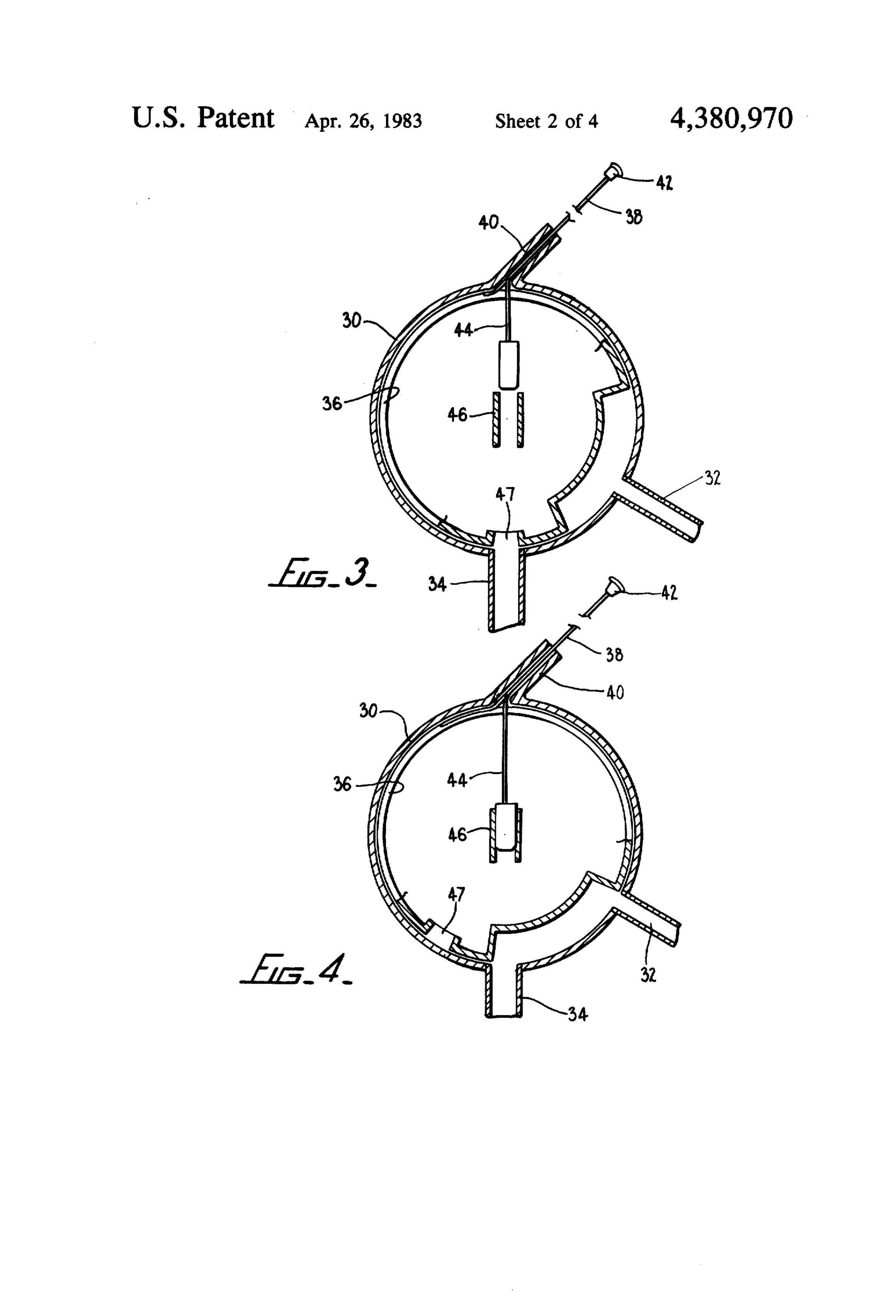
FIG. 2 is a horizontal sectional view through the However, as the exhaust pipe 10 and container 18 are apparatus of FIG. 1; heated by exhaust gases production of hydrogen and FIG. 3 is a horizontal sectional view of a control oxygen commences. When the rate of gas production mechanism for the apparatus of FIGS. 1 and 2, in a first 65 has reached a satisfactory level the main jet can be position; closed so that the engine is operating largely on the FIG. 4 is a view similar to FIG. 3 showing the con hydrogen and oxygen produced by dissociation of wa trol mechanism in a second position; ter.
Page 7
A suitable control mechanism for switching from It follows that with the system of the present inven total petrol fuel to mainly hydrogen and oxygen fuel is tion gas is produced only as required and in amounts shown in FIGS. 3 and 4. The control mechanism shown which correspond with the demands of the engine. in FIGS. 3 and 4 comprises an outer cylinder 30 which The water may be supplied to the inlet port 14 from is arranged to be mounted on top of a carburettor be a supply tank which may be made of non ferrous metal tween the carburettor and a conventional air filter. The and have a filler hole and cap with a vent on top. Con outer cylinder 30 is in fluid communication with the veniently, water is supplied to the outlet port 14 by outlet means 16 of the chamber 12. The outer cylinder means of gravity through a conduit from the supply 30 contains a signal port 32 and a carburettor port 34 10 tank. The supply tank and conduit may be provided through which hydrogen and oxygen enters the carbu with a flow metering means such as a flow control tap rettor. A ported cylinder 36 is snugly fitted within the or needle valve with a maximum flow stop. The rate of outer cylinder 30. The ported cylinder 36 is mounted drops flow may be metered to a rate of the order of twenty for partial rotation. The partial rotation of the ported sufficient of water per minute and generally this supplies cylinder 36 is achieved by means of a cable 38 having 15 it is foundwater for operation of a car engine. However, one end attached to the ported cylinder 36. The cable 38 pressure in the whenthat the engine is working hard and passes through an aperture in the outer cylinder 30 and normal can be chamber induced 12 is low more water than through the flow metering along a conduit 40. The conduit 40 terminates at an means thus ensuring that sufficient water appropriate location such as the dashboard of the vehi the increased demands of the engine. Theischamber available for cle. The free end of the cable 38 is provided with a knob 20 preferably fitted to the hottest part of the exhaust 12 is pipe 42. 10 to ensure maximum heat input. Further the assembly A further cable 42 is mounted to the cable 38. The of chamber 12 and container 18 with the adjacent por further cable 44 terminates adjacent the entrance to a tions of the exhaust pipe 10 is preferably thermally main jet 46 in the position shown in FIG. 3. insulated to provide for efficient heat transfer to the In operation, the ported cylinder 36 is initially located 25 walls of the chamber 12. The assembly is also preferably in the position shown in FIG. 3. In this position the gas constructed of corrosion resistant material such as stain initially produced by dissociation of water as the cham less steel. The initial operation of the engine may be ber 12 is heated is directed from the carburettor port 36 achieved by alternative means to that described above.
through the signal port 32. The signal port 32 is in comFor example, an electrical heating element could be munication with an alarm means such as an audible or 30 located in the walls of the chamber 12 to initially heat visual alarm. As the rate of gas production increases it the walls to a temperature sufficient for gas production gradually becomes sufficient to replace the petrol intro to commence. The only disadvantage of this system is duced into the carburettor through the main jet 46. The that there would be a delay from energising the electri alarm means is arranged to be activated at this point. cal element until the vehicle could be driven. Further, Upon activation of the alarm means the cable 38 may 35 the invention has been particularly described in relation be pushed using the knob 42, so as to partially rotate the to an engine provided with a conventional carburettor cylinder 36 from the position shown in FIG. 3 to that with idle jet.
shown in FIG. 4. In this position the cable 44 enters the Still further, the invention can be applied to all types main jet 46 and blocks it to prevent petrol entering the of internal combustion engines such as four stroke and carburettor through the main jet 46. Also, the signal two stroke engines, diesel engines, rotary engines, jet port 32 is blocked and the hydrogen and oxygen mix engines, and gas turbines. All that is required is that ture passes through the carburettor port 34 to enter the means be provided for transferring heat from the ex carburettor through port 47. Reverse movement of the haust means of the engine to water to cause thermal dissociation of the water into hydrogen and oxygen.
cable 38 opens the main jet 46 and signal port 32 and 45 The closes the carburettor port 34. With the system of the ducedhydrogen and oxygen mixture so produced is intro present invention the rate of production of hydrogen bustioninto a combustion chamber of the internal com and oxygen raises with the temperature of the exhaust above. engine in a manner analogous to that described gases and the amount of heat transferred to the walls of the chamber 12. Thus, when the engine is working hard 0 entModifications and variations such as would be appar the gases are hotter and of greater volume. The amount of the present invention. are to a skilled addressee deemed within the scope
For example, when it is re of heat transferred to the chamber 12 therefore in quired to run solely on hydrogen and oxygen, the con creases and so does the rate of gas production. ventional fuel can be turned off at source. In a conven Further, the outlet port 16 is in communication with tional carburettor this can be achieved in the following the carburettor choke and thus the pressure inside the 55 manner. A cable can be passed through a hole in the top chamber 12 is below atmospheric pressure. Under re of the float chamber of the carburettor to engage the duced pressure the temperature required to be reached float valve lever. The cable may be curved within the for dissociation of water to take place is lower than that float chamber so as to present a cam action when actu required at atmospheric pressure. Thus, gas production ated. The cable passes along a conduit and terminates at proceeds more readily in the chamber 12 than it would the dashboard of the vehicle in a knob. When the knob at atmospheric pressure. Further, when the engine is is depressed the curved portion of the cable exerts pres working hard the degree of induction in the carburettor sure on the float valve lever and thereby holds closed choke is increased and the pressure inside the chamber the petrol valve.
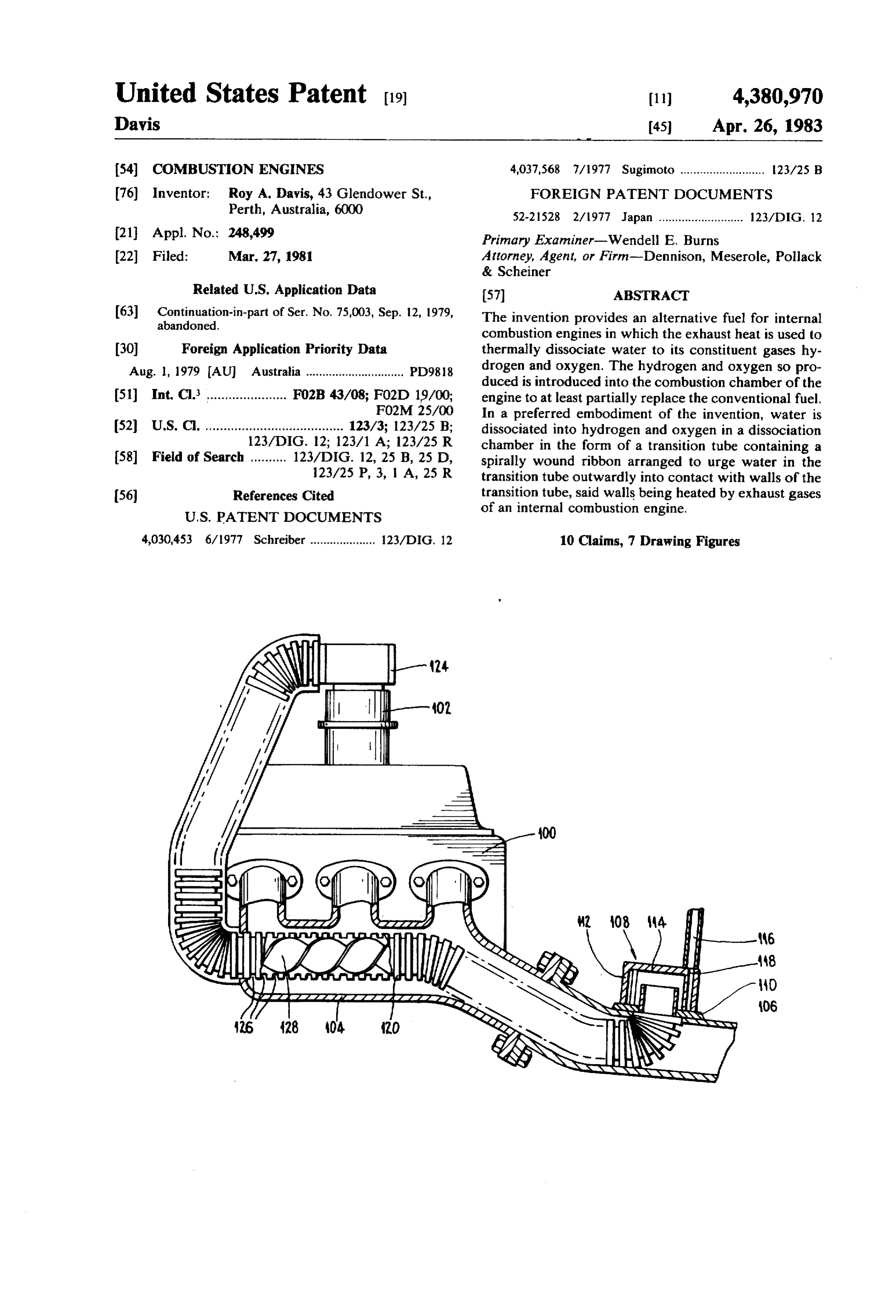
12 is further lowered. Thus, gas production is achieved In FIG. 5 of the accompanying drawings, there is at yet lower temperatures. It is advantageous to pro 65 shown a modified and improved embodiment of the duce gas at lower temperatures since the gas has greater present invention. In the embodiment of FIG. 5 there is density and therefore for a given volume more gas can shown schematically an internal combustion engine 100 be introduced to the combustion chamber. having a carburettor 102 on the inlet side thereof and an
Page 8
exhaust manifold 104 on the outlet side thereof. The Clearly, the ribbon 128 need only extend part way exhaust manifold 104 is connected to an exhaust pipe through the transition tube 120 particularly where it is 106. within the exhaust pipe 106 and exhaust manifold 104 A housing 108 is mounted on the exhaust pipe 106. but should extend for a length sufficient to ensure effi The housing 108 comprises a base 110 mounted directly s cient dissociation of the steam particles. Further, the on the exhaust pipe 106. The base 110 contains an aper whole system can be thermally insulated to avoid undue ture which corresponds in size, shape and location with heat loss.
an aperture in the exhaust pipe 106. The housing 108 The ribbon 128 may be constructed of copper en further comprises a wall 112 upstanding from the base capulated with high carbon steel to prevent the copper 108 and a roof 114. O melting especially where the ribbon 128 contacts the A pipe 116 is mounted to the top of the roof 114. transition tube 120. The copper core of the ribbon 128 Further, the roof 114 contains a small orifice 118 lead transmits heat along the ribbon 128 and enables it to ing from the adjacent end of the pipe 116 to the interior adopt a uniform temperature along its length. Also, the of the housing 108. presence of the heated ribbon 128 assists in heating the A dissociation chamber is in the form of a transition 15 centre of the transition tube 120 for more efficient disso tube 120 which has one end projecting through the ciation.
mating apertures in the exhaust pipe 106 and the base The dissociation tube 120 may conveniently be 110 to form a transition tube inlet. formed of stainless steel and is preferably flexible to The transition tube 120 leads from the said one end enable it to conform to the curvature of the exhaust of 20 the engine 100.
through the exhaust pipe 106 and the exhaust manifold 104. The transition tube 120 then passes through a wall byDissociation of the steam particles may be enhanced including a sound projecting device in the air intake of the exhaust manifold 104 and leads to a transition tube outlet at an adaptor 124 arranged to be connected system of the carburettor 102. The sound projecting device faces the carburettor air intake throat. Such a in the air intake of the carburettor 102.
25 system is illustrated schematically in FIGS. 6 and 7.
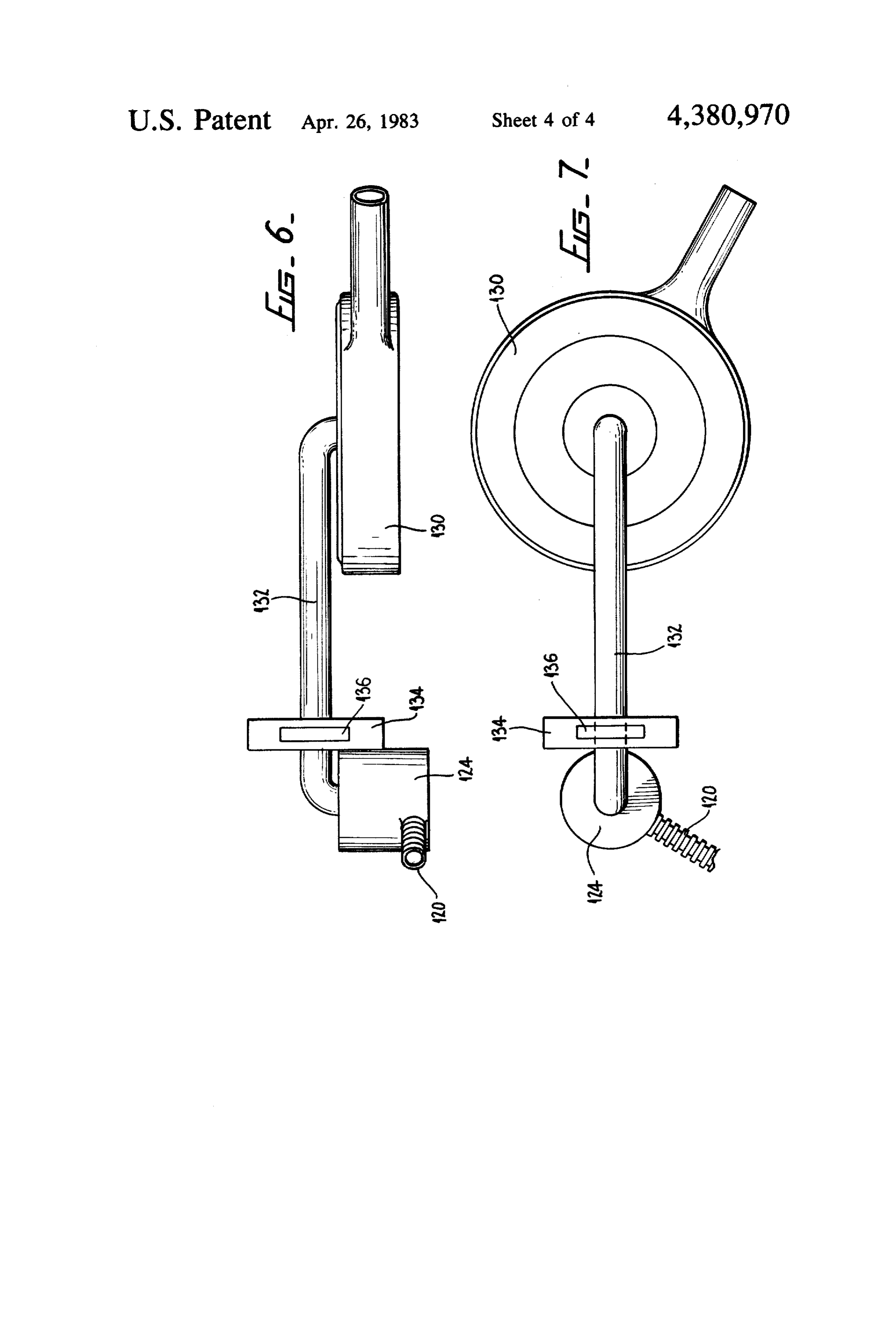
The transition tube 120 is internally and externally In FIGS. 6 and 7 there is shown the adaptor 124 of transversely ribbed as shown in the drawing. This forms FIG. 5 and the adjacent end of the transition tube 120. internally of the transition tube 120 a number of trans In addition, there is shown a conventional air cleaner verse cells 126. Further, throughout its length from the 130 which is connected to the adaptor 124 by an induc transition tube inlet to the transition tube outlet the 30 tion tube 132. The induction tube 132 has mounted transition tube 120 contains a spirally wound ribbon about it a housing 134 containing a sound projector 136. 128. Preferably, as shown in FIG. 5 the ribbon 128 is a The sound projector 136 is so mounted in the induction snug fit inside the transition tube 120 so as to contact the tube 132 as to allow air flow around it. Conveniently the inner walls of the transition tube 120 between the cells sound projector 136 is energised by electric current 126, 35 drawn from the battery of the vehicle. in use, and as described above, the engine 100 may be A resonator is formed of the carburettor throat, in operated in conventional manner using a hydrocarbon duction tube 132, cylinder induction space and transi fuel and air mixture. Hot exhaust gases are expelled tion tube 120. The gas mixture within the resonator is through the exhaust manifold 104 and exhaust pipe 106. subject to the sound waves produced by the sound The hot exhaust gases cause the exhaust manifold 104, projector 136. This imparts energy to water molecules exhaust pipe 106 and the transition tube 120 to become in the system and raises their level of excitation thus heated. facilitating dissociation into hydrogen and oxygen. Water is then admitted through the pipe 116 and the At small throttle openings when the carburettor orifice 118 into the chamber 108. In the arrangement valve is almost closed, the sound is mostly diverted into shown, the water falls under the influence of gravity 45 the transition tube 120.
onto the base 110. The base 110 is itself heated by con As the carburettor valve is opened more of the sound duction from the exhaust pipe 106. Thus, the water enters the cylinder induction spaces during the induc becomes heated and converted to steam. The transition tion stroke. It should also be noted that the use of sound tube 120 is a communication with the air inlet of the in the carburettor and cylinder induction spaces in carburettor 102 and is thus under vacuum whilst the SO proves the atomisation of liquid fuel such as petrol, in engine 100 is operating. Therefore, the steam is drawn air and thus leads to more efficient combustion of the into the transition tube 120 through the transition tube liquid fuel.
inlet. The steam passes through the transition tube 120 I claim:
and in so doing is imparted with a spiral motion by the 1. An internal combustion engine comprising inlet ribbon 128. This spiral motion urges the steam particles 55 means, a combustion chamber and exhaust means, a outwardly into the cells 126. The cells 126 project into dissociation chamber in heat communication with the the exhaust gas steam of the engine 100 and are thus the exhaust means, inlet means for the dissociation chamber hottest part of the transition tube 120 particuarly at their and outlet means for the dissociation chamber, means outermost ends. The use of the ribbon 128 also has the for introducing water to the dissociation chamber advantage of urging the steam particles into contact through the inlet means thereof, and means for intro with the hot surface of the transition tube 120. Without ducing gases into the inlet means of the combustion the ribbon 128 the steam particles would tend to expand chamber from the dissociation chamber from the outlet away from the hot surface to the cooler centre of the means thereof, wherein said dissociation chamber is in bore and thus less efficient dissociation would take the form of a transition tube located at least in part place. 65 within the exhaust means and said transition tube con Whilst in the cells 126 the steam is heated and dissoci tains a spirally wound ribbon along at least part of its ated into hydrogen and oxygen gases which proceed length located within the exhaust means, whereby in through the transition tube 120 into the carburettor 102. use, water in the transition tube is urged outwardly into
Page 9
contact with walls of the transition tube and hydrogen and at least part of the transition tube is located within and oxygen so produced is introduced into the combus said conduit.
tion chamber through the inlet means thereof. 8. An internal combustion engine according to claim 2. An internal combustion engine according to claim 1, which comprises a conventional carburettor having a 1, wherein walls of the transition tube within the ex 5 main jet and a pilot jet, means being provided to selec haust means are internally and externally transversely tively block the main jet and the means for introducing ribbed so as to form transverse cells into which the the dissociation products to the inlet means of the con water is urged. bustion chamber to enable the combustion chamber to 3. An internal combustion engine according to claim selectively receive liquid fuel from the main jet but also 2, wherein the ribbon is a snug fit within the transition 10 to receive gas from the transition tube. tube.
4. An internal combustion engine according to claim 1, 9.which An internal combustion engine according to claim 1, wherein a housing is mounted to the exhaust means in to subjectfurther comprises a sound projector arranged gas mixtures within the engine to sound heat conductive relation therewith and the means for waves to raise the excitation levels of water molecules introducing water to the dissociation chamber first in 15 therein troduces the water to the housing where the water is and facilitate dissociation thereof. converted to steam prior to entering the dissociation 10. An exhaust means for an internal combustion chamber. engine having a dissociation chamber in heat communi 5. An internal combustion engine according to claim cation therewith, said dissociation chamber having 1, wherein the inlet means of the combustion chamber 20 water inlet means and gas outlet means, means for cou includes an air intake means and the transition tube is in pling the gas outlet means to an inlet means of an inter fluid communication with the air intake means. nal combustion engine and means for coupling the 6. An internal combustion engine according to claim water inlet means to a supply of water, wherein the 1, in which the transition tube is in fluid communication dissociation chamber is in the form of a transition tube with the combustion chamber and the engine comprises 25 located at least in part within the exhaust means and said a member which is arranged to induce sub-atmospheric transition tube contains a spirally wound ribbon along at pressure in the combustion chamber during operation of least part of its length located within the exhaust means, the engine. whereby, in use, water in the transition tube is urged 7. An internal combustion engine according to claim outwardly into contact with walls of the transition tube. 1, in which the exhaust means is in the form of a conduit 30 t sk k
Provenance
- Collection
- Cited prior art
- Original PDF
- patentimages.storage.googleapis.com →
- Filed
- 1981-03-27
- Pages
- 9
- Method
- pdftotext (the PDF's own text layer) + pdftoppm 300dpi page scans
- Source
- Google Patents bibliographic record
- Granted
- 1983-04-26
- Inventors
- Roy A. Davis
- Transcribed from
- patentimages.storage.googleapis.com →