patent · US5183011A
Method of controlling the supply of fuel in hydrogen-fueled engine
2 February 1993
Page 1 — bibliographic record
United States Patent (19) 11) Patent Number: 5,183,011 Fujii et al. 45) Date of Patent: Feb. 2, 1993 (54) METHOD OF CONTROLLING THE SUPPLY FOREIGN PATENT DOCUMENTS
OF FUEL N HYDROGEN-FUELED ENGINE
(75) Inventors: Isao Fujii; Yoshio Ajiki; Yoichi 243026 9/1990 Japan. Ishida; Hiromi Matsuura, all of
Saitama, Japan Primary Examiner-E. Rollins Cross
Assistant Examiner-Erick Solis 73) Assignee: Honda Giken Kogyo Kabushiki Attorney, Agent, or Firm-Lyon & Lyon Kaisha, Tokyo, Japan 57 ABSTRACT (21) Appl. No.: 870,543 A hydrogen-fueled engine has an intake valve, a hydro (22 Filed: Apr. 17, 1992 gen supply valve and an exhaust valve, which are oper ated to open and close relative to a combustion cham (30) Foreign Application Priority Data ber, and a control valve provided in a hydrogen supply Apr. 17, 1991 JP Japan ....................... ............. 3-85489 pipe to control the output of the engine through the control of the flow amount of hydrogen. This control 51) Int. Cl. .............................................. FO2B 75/12 valve is a pressure control valve to adjust the pressure 52 U.S. C. ............................ 123/1 A; 123/DIG. 12 of hydrogen to be supplied. The hydrogen supply valve 58) Field of Search ............... 123/DIG. 12, 1 A, 1 R is operated by an apparatus of the type capable of ad justing the lift and the valve timing. In this engine, the (56) References Cited hydrogen to be supplied to the combustion chamber is
to load conditions by both the pressure control valve 4,018, 190 4/1977 Henault ...................... 123/DIG. 12 and the hydrogen supply valve under at least one of 4,389,981 6/1983 Meyer ......................... 123/DIG, 12 either the low-load condition or the high-load condi 4,508,064 4/1985 Watanabe. ... 123/DIG, 12 tion, and substantially only by the pressure control 4,520,763 6/1985 Lynch et al. ....... 123/DIG. 12 valve under an intermediate-load condition.
5,067,447 1/1991 waki et al. ........ :123/DIG. 12 5,115,768 5/1992 Peschka et al. ............. 123/DEG, 12 7 Claims, 3 Drawing Sheets
Page 2
Drawing sheet — no readable text.
Page 3
Drawing sheet — no readable text.
Page 4
Drawing sheet — no readable text.
Page 5
region A3, the low-load region B3, and the high-load
METHOD OF CONTROLLING THE SUPPLY OF region B4 shown in FIG. 3.
FUEL IN HYDROGEN-FUELED ENGINE In order to attain the above-mentioned object, there is provided a method of controlling the fuel in a hydro
BACKGROUND OF THE INVENTION 5 gen-fueled engine comprising an intake valve, a hydro This invention relates to a method of controlling the gen valves supply valve and an exhaust valve, each of the being operated to open and close relative to a fuel in a hydrogen-fueled engine. combustion chamber, and a control valve provided in a One means of controlling the fuel in a conventional hydrogen supply pipe to control the output of the en gas-fueled engine is disclosed in Japanese Published 10 gine through the control of the flow amount of the Examined Patent Application No. 23703/1990, in hydrogen, the control valve being a pressure control which a fuel intake passage is provided separate from valve to adjust the pressure of the hydrogen to be sup the air intake passage and each of the passages is con plied, the hydrogen supply valve being of a type capa trolled by a throttle valve. Another fuel control means ble of adjusting the lift and the valve timing, wherein is disclosed in Japanese Published Examined Patent 15 the method is characterized in that the hydrogen to be Application No. 43026/1990, in which there are pro supplied to the combustion chamber is controlled based vided, in parallel, a premixed gas passage for feeding air on control signals corresponding to load conditions by and the fuel after mixing them together and a direct both the pressure control valve and the hydrogen sup injection passage for directly injecting the fuel into the ply valve under at least one of either the low-load con engine so that the above-mentioned two passages can be 20 dition and the high-load condition, and substantially used either separately or together depending on the only by the pressure control valve under an intermedi load or the rotational speed. ate-load condition.
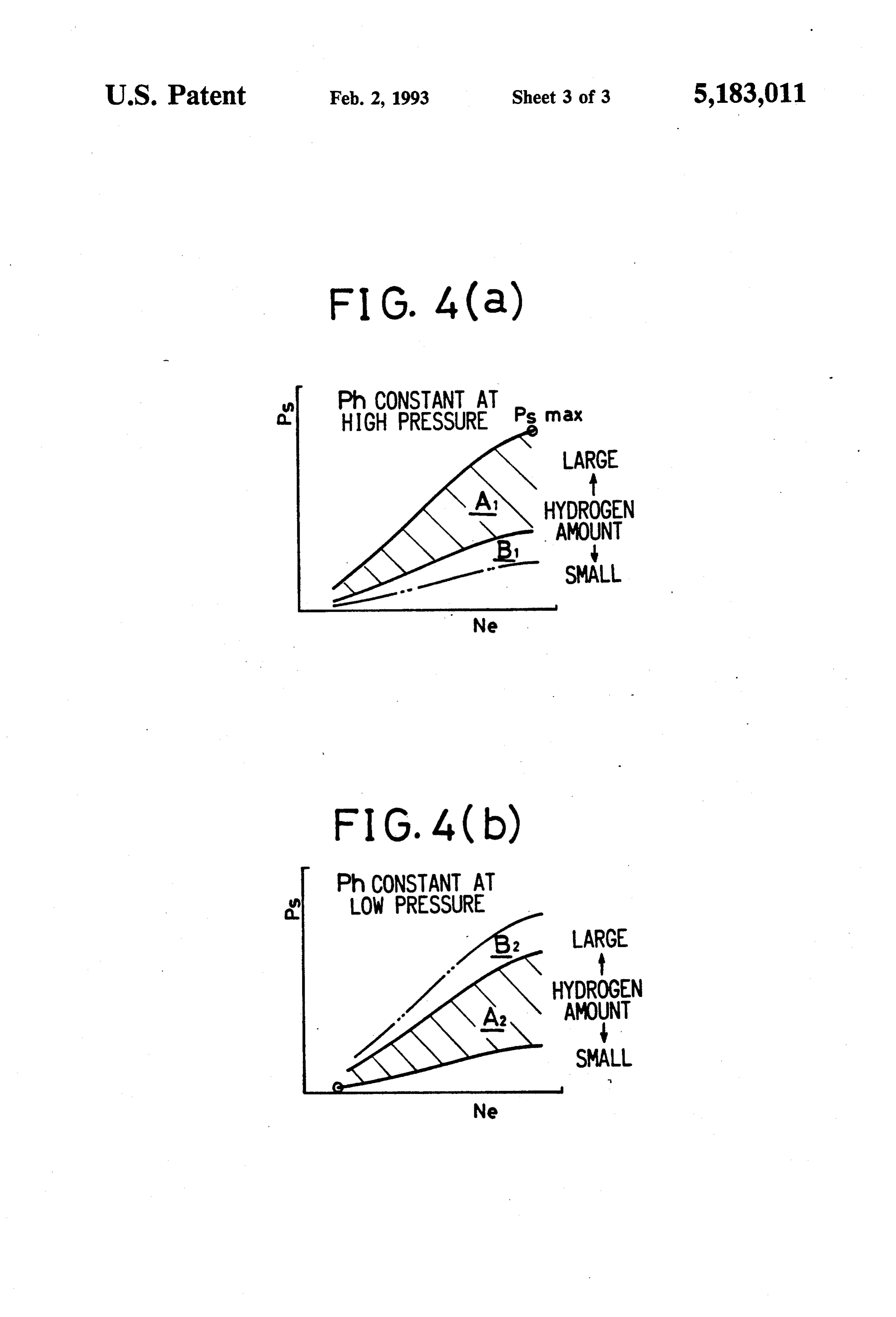
However, since the throttle valve in the former publi Since the method of this invention is arranged as cation has manufacturing errors and the premixed gas described above, the required amount of fuel is supplied passage in the latter publication has lower adjustment 25 through adjustment of the fuel amount by controlling accuracies near the minimum and the maximum opening mainly the pressure control valve under an intermedi degrees, it is practically impossible to accurately con ate-load condition, and by controlling the lift and the trol the fuel amount. The graphs of FIG. 4(a) and FIG. valve timing of the hydrogen control valve under a 4(b) show controllable ranges of the output Ps and the 30 high-load condition and/or a low-load condition aside rotational speed Ne by the conventional throttle valve from the control by the pressure control valve. at high and low hydrogen fuel supply pressures Ph, BRIEF DESCRIPTION OF THE DRAWINGS respectively. It is impossible to accurately control the hydrogen amount over the entire control ranges in tages The above and other objects and the attendant advan either of the conditions in which the hydrogen supply 35 reference of this invention will become readily apparent by pressure Ph is kept constant at a high pressure or in consideredtointheconjunction following detailed description when with the accompanying which it is kept constant at a low pressure. drawings wherein:
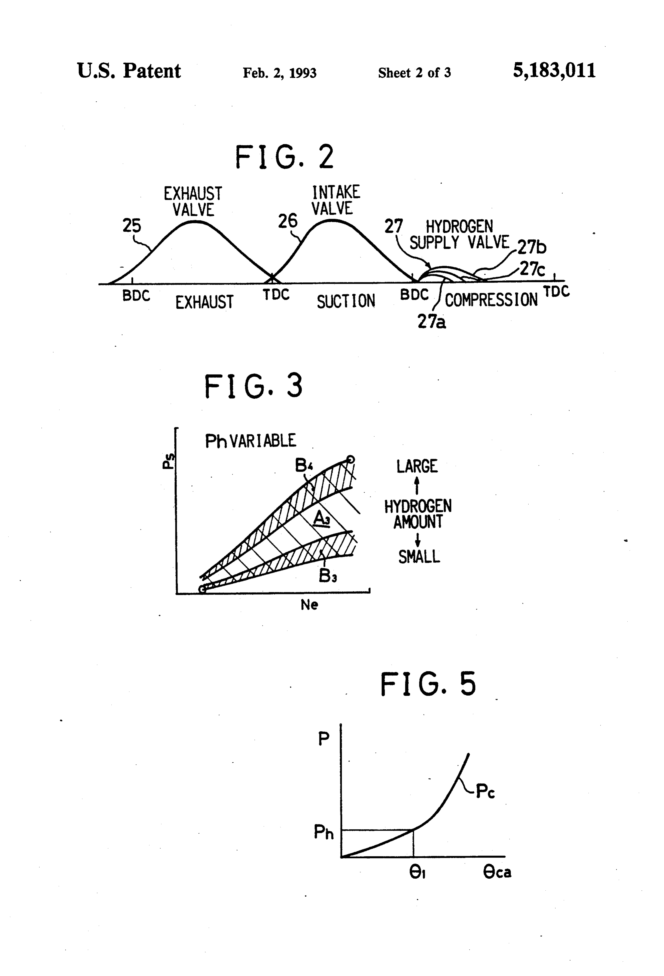
If the hydrogen supply pressure Phis kept constant at a high pressure, an accurate control can be made in the anFIG. 1 is a schematic diagram of the components of internal combustion engine and controls used for the region A1 in FIG. 4(a) and therefore it is possible to method of this invention as applied to that engine; obtain and maintain a target maximum output Ps max. FIG. 2 is a diagram showing the valve timing; However, since there is a limit to the minimum area that FIG. 3 is a diagram showing the operation of the can be obtained accurately due to the manufacturing engine of this invention;
errors or the like of the valve system, it is impossible to accurately control a minimum hydrogen supply 45 tionFIG. 4(a) and 4(b) are diagrams showing the opera of a conventional engine; and amount. As a result, the control becomes inaccurate in FIG. 5 is a diagram showing the operation of the the low-load region including idling rotation, i.e., in the hydrogen supply.
region B1 in FIG. 4(a).
On the other hand, if the hydrogen supply pressure DETAILED DESCRIPTION OF A PREFERRED
Ph is kept constant at allow pressure, a stable control 50 EMBODIMENT can be made in the region A2 in FIG. 4(b), but the con An embodiment of this invention will now be de trol becomes unstable in the region B2 where the load is scribed. In FIG. 1, numeral 1 denotes a hydrogen-fueled high and the hydrogen supply amount is subject to engine, numeral 2 denotes its cylinder block, numeral 3 limitations. The reason is that, when a curve PC in FIG. denotes a piston, numeral 4 denotes a cylinderhead, and 5 is supposed to denote the change in the cylinder inter 55 numeral 5 denotes combustion chamber. In the cylinder nal pressure P in accordance with the crank rotational head 4, there are provided an intake port 6, a hydrogen angle 6ca, the crank angle 6 at the point where the supply port 7 and an exhaust port 8, each of which is in hydrogen pressure Ph and the internal pressure Po coin fluid flow communication with the combustion cham cide is the supply limit and, consequently, the hydrogen ber. In the intake port 6, there is provided an intake supply amount above the low hydrogen supply pressure valve 10 which is driven by a cam 9. The exhaust port Ph is restricted. 8 is provided with an exhaust valve (not shown) which OBJECT AND SUMMARY OF THE INVENTION is driven by a cam (not shown), all in a conventional
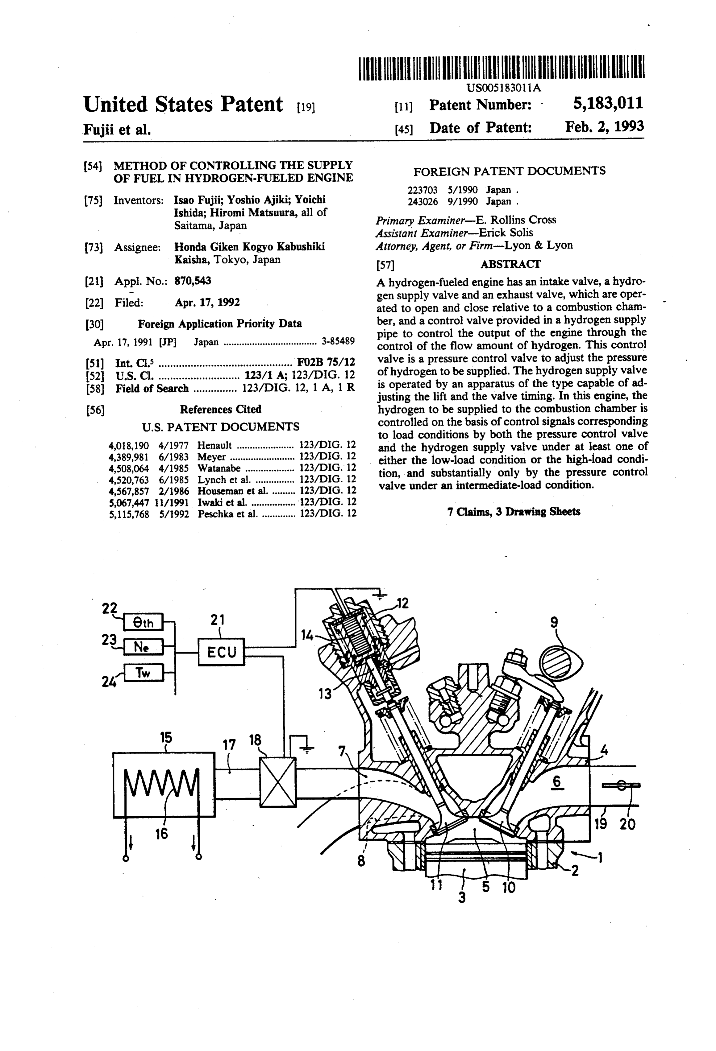
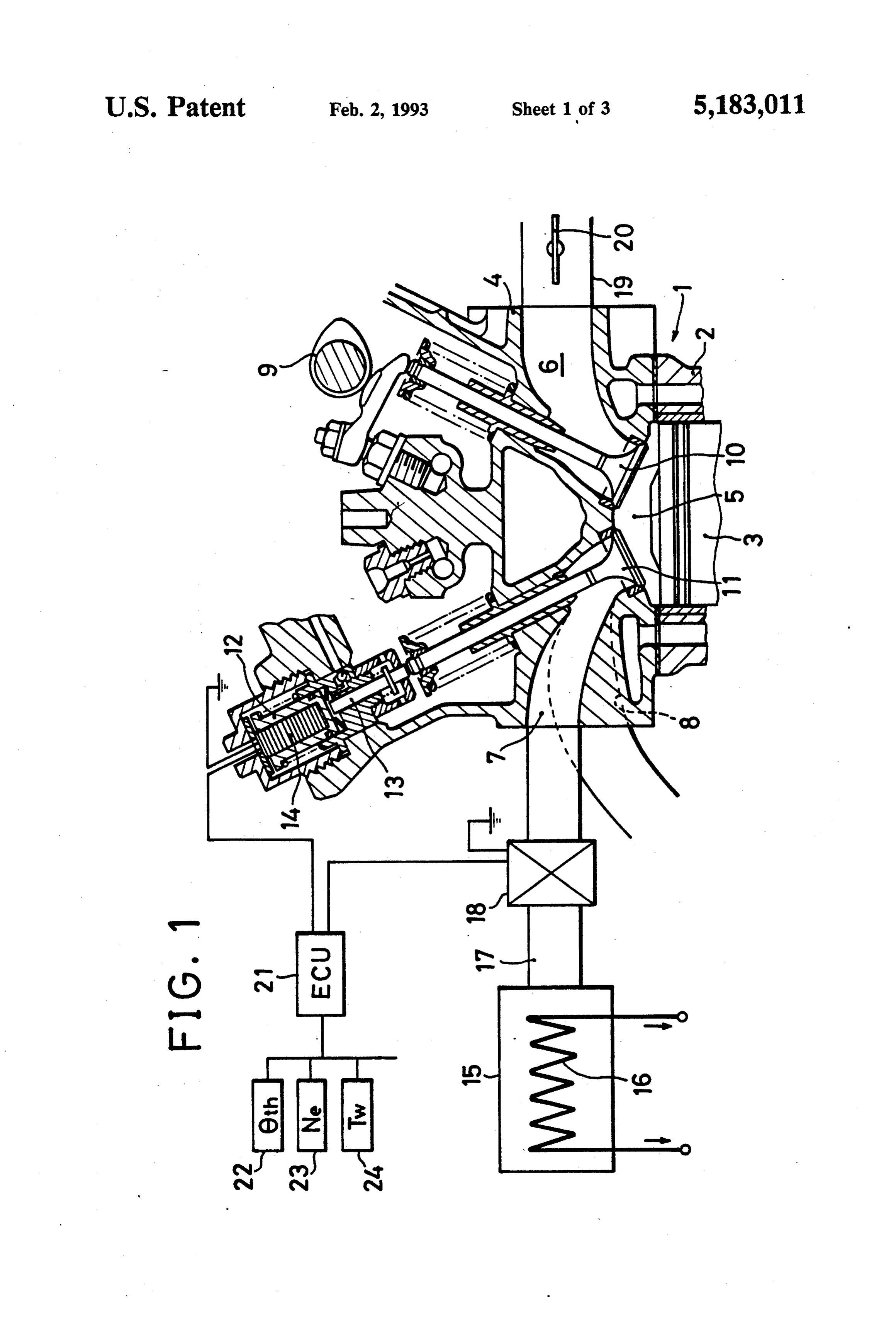
This invention has an object of providing a method of In the hydrogen supply port 7, there is provided a carrying out an accurate fuel control irrespective of the 65 hydrogen supply valve 11 that is urged in the open magnitude of the load as well as of the hydrogen pres direction by an electrostrictive actuator 12 via a rod 13. sure changes so that an accurate fuel control can be The electrostrictive actuator 12 comprises a multitude made over the entire ranges of the intermediate-load of laminated piezoelectric elements 14 that increase in
Page 6
thickness in accordance with the voltage applied In the above-described embodiment, the intake valve thereto to thereby push the rod 13 toward the hydrogen 10 and the non-illustrated exhaust valve are arranged to supply valve 11. be driven by the cam. They may, however, be arranged Hydrogen gas is stored in a storage container 15 in an to be hydraulically driven. In addition, the control by adsorbed condition into, e.g., a hydrogen-adsorbing means of the hydrogen supply valve 11 may be em alloy metal. The adsorbed hydrogen is released by heat ployed only under one of either the low-load condition ing with a heat exchanger 16 through which engine or the high-load condition.
cooling water is caused to flow, and flows through a As described above, in this invention, the lift and the hydrogen supply pipe 17 to the hydrogen supply port 7. valve timing of the hydrogen supply valve is controlled The hydrogen supply pressure is controlled by a pres O aside from the control of the hydrogen pressure. There sure control valve 18 which is provided in an intermedi fore, adjustment can be made without extremely throt ate location in the hydrogen supply pipe 17. An electro tling the hydrogen pressure control valve in the low magnetic pressure control valve or a throttle valve is load operating region, especially during idling rotation. used as the pressure control valve 18. This brings about an advantage in that the amount of Since hydrogen gas has wide inflammable limits both 15 hydrogen supply can be maintained highly accurate. In in rich and lean ranges, the engine rotation can be con addition, an accurate adjustment can also be made in a trolled by controlling its supply amount even if the air high-load operating region. Furthermore, if the control flowing into the intake port 6 is not controlled by a apparatus is set such that the hydrogen supply pressure throttle valve. It follows that normally there is no need becomes high under the high-load operating condition, to provide a throttle valve. However, in a region of 20 the flow area of the pressure control valve can be mini extremely low-load conditions, such as in idling, there mized. This brings about another advantage in that the are cases where an extremely lean condition occurs in pressure control valve can be made smaller. which the hydrogen amount is particularly small rela It is readily apparent that the above-described tive to the suction air amount, thereby making it diffi method of controlling the fuel in a hydrogen-fueled cult to ignite. Therefore, a throttle valve 20 may be 25 engine has the advantage of wide commercial utility. It provided in an intake passage 19 which leads to the should be understood that the specific form of the in intake port 6 so that a rich condition can be made by vention hereinabove described is intended to be repre reducing or closing the throttle valve 20 under an ex sentative only, as certain modifications within the scope tremely low-load condition. of these teachings will be apparent to those skilled in the The above-mentioned electrostrictive actuator 12 and 30 art. Accordingly, reference should be made to the foll the pressure control valve 18 are controlled by a control lowing claims in determining the full scope of the inven apparatus 21 aided by a computer. This control appara tion.
tus 21 operates to generate a control output based on What is claimed is:
signals from an accelerator pedal opening degree sensor 1. A method of controlling the supply of fuel in a 22, a rotational speed sensor 23, a cooling water temper 35 hydrogen-fueled engine having an intake valve, a hy ature sensor 24, and other appropriate sensors. drogen supply valve and an exhaust valve with each of The intake valve 10 and the non-illustrated exhaust said valves being operated to open and close relative to valve are driven by a crankshaft via a normal can shaft a combustion chamber, and a control valve provided in and opens and closes in a timing shown in FIG. 2. In. a hydrogen supply pipe to control an output of said FIG. 2, numeral 25 denotes an exhaust valve lift curve 40 engine through control of a flow amount of hydrogen, and numeral 26 denotes an intake valve lift curve. When said control valve being a pressure control valve for the intake is finished near bottom dead center BDC of adjusting the pressure of hydrogen to be supplied, said the crank shaft, the intake valve 10 is closed. When the hydrogen supply valve being operated by means capa compression stroke starts, the hydrogen supply valve 11 ble of adjusting lift and valve timing of the hydrogen is opened as shown by curves 27 to supply hydrogen, 45 supply valve, wherein said method is characterized in and the hydrogen is mixed into the previously sucked that the amount of hydrogen being supplied to said air to perform a compression ignition. In the curves 27, combustion chamber is controlled based on control numeral 27a denotes a minimum-load curve and nu signals corresponding to load conditions by both said meral 27b denotes a maximum-load curve. A control is pressure control valve and said hydrogen supply valve carried out between these two curves 27a, 27b depend under at least one of a low-load condition and a high ing on the load conditions. For example, numeral 27c load condition, and substantially only by said pressure denotes an intermediate-load curve to show an opera control valve under an intermediate-load condition. tion under an intermediate-load condition. 2. The method of controlling the supply of fuel in a In the above-described apparatus, the hydrogen sup hydrogen-fueled engine according to claim 1, wherein ply amount is mainly controlled by the pressure control 55 the lift of said hydrogen supply valve is controlled by an valve 18. Normally, due to the manufacturing errors of electrostrictive actuator.
the pressure control valve 18, or due to low control 3. The method of controlling the supply of fuel in a accuracies near the minimum or the maximum opening hydrogen-fueled engine according to claim 1, wherein degree, pressure variations in the hydrogen supply the amount of hydrogen being supplied to said combus source are likely to occur and the hydrogen supply tion chamber is controlled by both said pressure control amount is likely to be inaccurate at the time of idling valve and said hydrogen supply valve under both low rotation speed, a low-load condition, and a high-load load and high-load conditions.
condition. In this invention, however, in addition to the 4. The method of controlling the supply of fuel in a control by the pressure control valve 18, the lift and the hydrogen-fueled engine according to claim 1, wherein valve timing of the hydrogen supply valve 11 are con 65 the supply of air is controlled under a low-load condi trolled by the control apparatus 21. Therefore, it is tion.
possible to supply an exact amount of hydrogen under 5. A method of controlling the supply of fuel in a all operating conditions. hydrogen-fueled engine having an air intake valve and a
Page 7
separate hydrogen supply valve with each of said only by said pressure control means under another dif valves being operated to open and close relative to a ferent engine operating condition. combustion chamber, for separately supplying air and 6. The method of claim 5, wherein the amount of hydrogen to the combustion chamber, and pressure hydrogen being supplied to said combustion chamber is control means for controlling the pressure of the hydro 5 controlled by both said pressure control means and said gen supplied to the hydrogen supply valve, said hydro hydrogen supply valve under at least one of either a gen supply valve having means for adjusting the open low-load or a high-load engine conditions. ing thereof, wherein said method includes the steps of 7. The method of claim 5, wherein said engine operat controlling the amount of hydrogen being supplied to ing conditions are determined by sensing at least engine said combustion chamber by both of said pressure con 10 speed, an engine throttle opening and engine tempera trol means and said hydrogen supply valve under at ture.
least one engine operating condition and substantially k
Provenance
- Collection
- Patents citing this work
- Original assignee
- Honda Motor Co Ltd
- Pages
- 7
- Method
- pdftotext (the PDF's own text layer) + pdftoppm 300dpi page scans
- Patent office record
- patents.google.com →
- Source
- Google Patents citing-documents table
- Inventors
- Isao Fujii; Yoshio Ajiki; Yoichi Ishida; Hiromi Matsuura; Honda Motor Co Ltd
- Published
- 1993-02-02
- Transcribed from
- patentimages.storage.googleapis.com →