patent · US4486701
Thermal energy conversion
4 December 1984
Page 1 — bibliographic record
3 ar. SR
United States atent (19) 11) Patent Number: 4,486,701 Cover (45) Date of Patent: Dec. 4, 1984 54) THERMAL ENERGY CONVERSION Primary Examiner-R. J. Hickey Attorney, Agent, or Firm-Knobbe, Martens, Olson & 76 Inventor: John H. Cover, 24742 Via San Bear
Fernando, Mission Viejo, Calif.
92691 57 ABSTRACT 21 Appl. No.: 342,391 A system is disclosed for converting thermal energy into chemical energy by means of a low-temperature 22) Filed: Jan. 25, 1982 process. A liquid flow loop with two vertical columns 51) Int. Cl. ............. . . . . . . . . . . . H02K 44/00; H02N 4/02 that are interconnected at the top and bottom circulates an electrically conducting fluid, such as mercury. A 52 U.S. C. ..................................... 322/2 R; 310/11; convective flow of this electrically conducting fluid is
58 Field of Search .................. 322/2 R, 2 A, 35, 47; established by heating the fluid in one of the columns 310/306, 300, 11; 290/43, 54, 1 R, 323/906; and cooling the fluid in the other column to establish a 204/129, 130 weight differential between the fluid in the two col umns. A magnetohydroynamic generator is placed on (56) References Cited this loop so that, as the fluid flows through the loop and
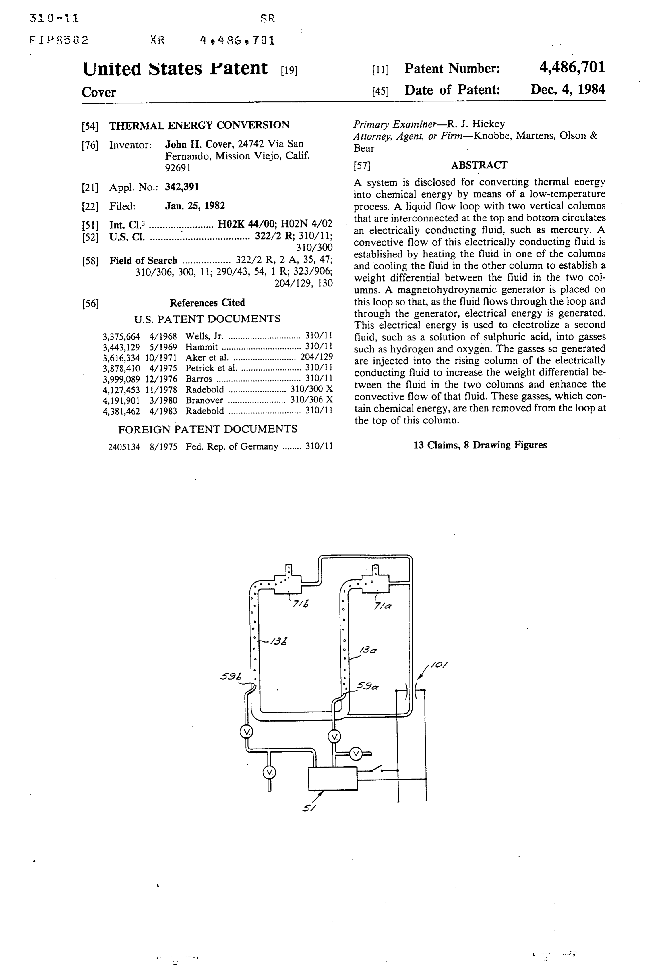
This electrical energy is used to electrolize a second 3,375,664 4/1968 Wells, Jr. .............................. 30/11 fluid, such as a solution of sulphuric acid, into gasses 3,443,129 5/1969 Hammit .......... ... 310/ such as hydrogen and oxygen. The gasses so generated 3,616,334 10/1971 Aker et al. ..... 204/129 are injected into the rising column of the electrically 3,878,410 4/1975 Petricket al... ... 310/11 conducting fluid to increase the weight differential be 3,999,089 12/1976 Barros ................................... 310/11 tween the fluid in the two columns and enhance the 4,127,453 1 1/1978 Radebold ........................ 310/300 X 4,191,901 3/1980 Branover ........................ 310/306 X convective flow of that fluid. These gasses, which con 4,381,462 4/1983 Radebold .............................. 30/1 tain chemical energy, are then removed from the loop at FOREIGN PATENT DOCUMENTS the top of this column.
2405134 8/1975 Fed. Rep. of Germany ........ 310/11 13 Claims, 8 Drawing Figures
Page 2
Drawing sheet — no readable text.
Page 3
Drawing sheet — no readable text.
Page 4
Drawing sheet — no readable text.
Page 5
which the fluid flows down is cooled to a temperature
THERMAL ENERGY CONVERSION of approximately 0-30 C. by means of a lower temper
BACKGROUND OF THE INVENTION
ature heat sink. The difference in the density of the fluid in these columns induces a convective flow of that fluid
With the advent of higher prices for the energy the through the loop. An MHD is coupled to one of these world consumes, much interest has been generated in vertical columns. The MHD includes a magnet that new sources of energy and in more efficient uses of this creates a strong magnetic field perpendicular to the energy. One of the energy conversion devices for flow of the fluid. As the fluid flows through throat which promise has been held is the magnetohydrody sections that have electrodes in contact with the fluid, namic generator (MHD). The basis for the operation of 10 an electric potential is generated between the elec an MHD is that passing an electrically conducting fluid trodes, causing an electric current to flow through the through a strong magnetic field will produce an electric electrodes and through an external electric circuit, from potential between opposite sides of the throat through which power may be drawn. The key to the present which the conducting fluid flows. The magnitude of the invention power generated with a given fluid is proportional to largely fedisback that the electric power so produced is to augment, or speed up, the flow of the velocity of the fluid through the throat. the conducting liquid. This is accomplished by using the MHD development has typically focused on the use electric power to dissociate water molecules in an elec of high temperature, high pressure gas or plasma, al though some systems have been developed using an trolytic solution, such as sulfuric acid, H2SO4, and in electrically conducting liquid. The temperature of the 20ject some or all of the gasses obtained (H2 and O2) into plasma or liquid used in these devices is usually on the the rising column of conducting liquid. The gas is re order of several hundred to a few thousand degrees moved from the loop at the top of the rising column and Celsius. The pressure under which the working fluid may be put to any of a number of uses. The remainder operates is also very high in most systems, on the order of the gases, which are not injected into the loop may be of several hundred to a few thousand pounds per square 25 taken directly from the electrolysis and put to use. inch. The use of such high temperature and pressure Among the possible uses for the gasses produced by this fluids limits the choice of materials out of which the system are burning to produce heat, power and pure system can be made. The high temperatures and high water using them to synthesize other fuels, such as pressures in these systems also make the systems prone methane or methanol. The introduction of the gas into to leaks and contribute to the rapid deterioration of 30 the rising column greatly reduces the density and machinery such as pumps used in the system. weight of the rising column of electrically conducting To provide the flow of conducting fluid through the liquid, and hence increases the weight difference be MHD throat, some systems have incorporated means tween the two columns of liquid. As the weight differ for establishing a convective flow of the fluid around a ence between the columns is increased, the convective closed loop. This convective flow is established by 35 flow of the liquid is increased, further increasing the heating the fluid at one point in the loop and cooling it production of electrical energy. With the increased at another. Such a system is shown in U.S. Pat. No. electrical output, more gasses are produced, and the 3,375,664 to Wells. It has been found, though, that the low velocity thus obtained has not been sufficient to convective creased, flow velocity of the liquid is further in which additionally increases the amount of permit the MHD to generate more than a few milliwatts 40 electric power generated by the MHD. The rate of of power even with vertical leg members up to 100 feet generation of the electrolyzed gasses is increased until tall. Another means of causing a flow of the conducting an equilibrium is established between fluid through an MHD loop has been to establish a the gasses and the viscous and othertheflow generation of retarding convective flow by introducing a gas into part of the forces.
loop to create a density differential between the fluid in 45 different sections of the loop. This has typically been entThe Thermal Energy Conversion System of the pres invention has numerous advantages over the MHD accomplished by boiling either the conducting liquid or a second fluid and using the vapor bubbles to leviate one systems previously developed. These advantages in column of the fluid. A system that operates in this man clude:
ner is disclosed in U.S. Pat. No. 3,443,129 to Hammitt. 50 (1) lower operating temperatures for the working Such systems, however, have been troublesome, since fluid;
boiling the fluid takes thermal energy from the system, (2) lower pressures in the system loop; reducing the heat in the conducting fluid in the rising (3) less severe constraints on the design and size of the column. Also, the height and temperature of the rising system components;
column are severely constrained by the need to prevent 55 (4) less severe constraints on the choice of materials condensation of the gas bubbles before they reach the out of which the systemn components are made; top of the column. and
SUMMARY OF THE INVENTION (5) greater power output with a smaller system due to increased operating efficiency.
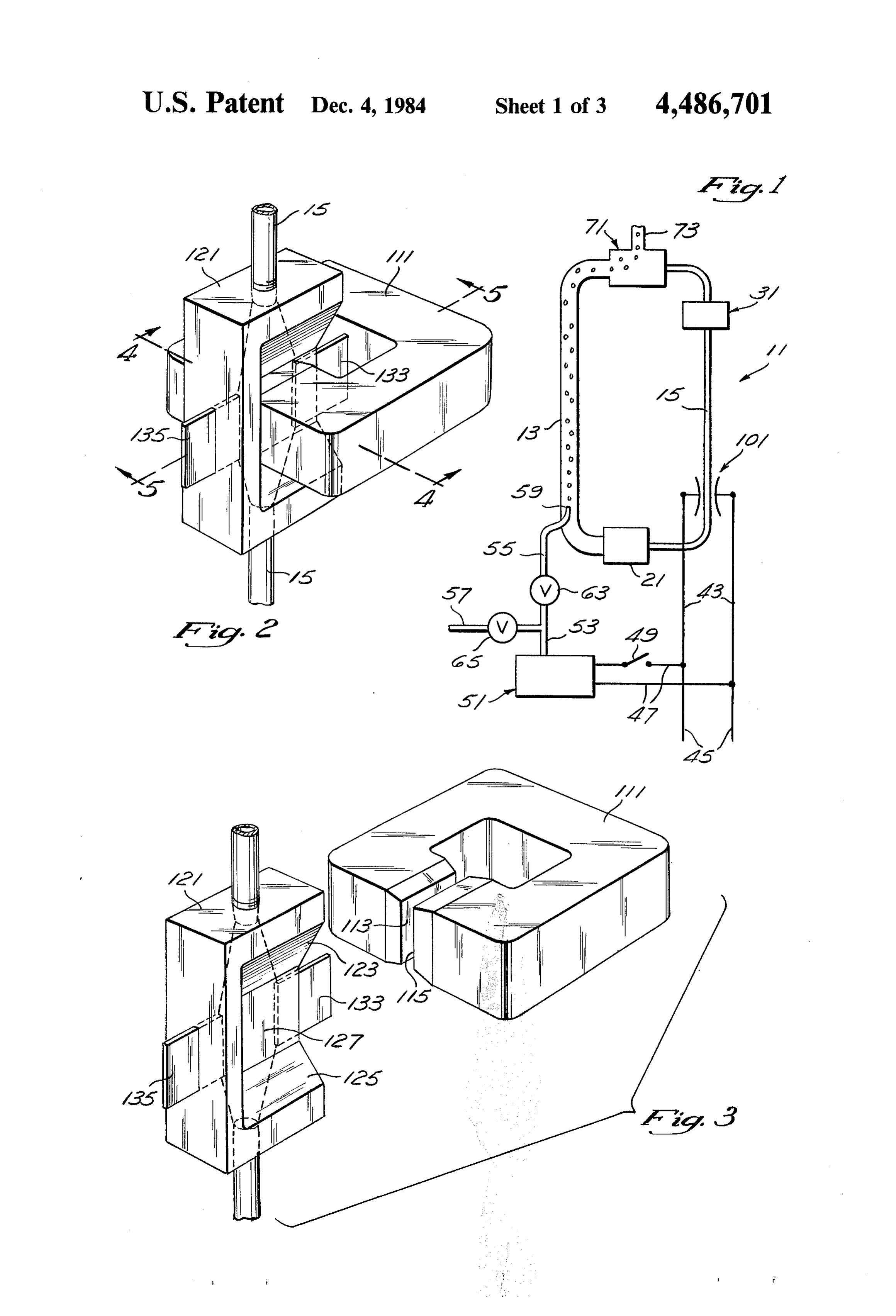
The present invention efficiently converts thermal 60 BRIEF DESCRIPTION OF THE DRAWINGS energy (heat) into an alternate form of energy by means of a low-temperature process. The invention consists of FIG. 1 is a schematic drawing of the Thermal Energy a fluid flow loop with two vertical columns intercon Conversion System of the present invention. nected at the top and the bottom. The fluid that flows in FIG. 2 is a perspective view of the magnetohydrody this loop is an electrically conducting fluid, preferably a 65 namic generator coupled to the fluid flow loop. liquid such as mercury. The column in which the fluid FIG. 3 is a perspective view of the magnetohydrody rises is heated to a temperature of approximately namic generator with the magnet withdrawn from the 40-150° C. by a thermal source and the column in throat section of the fluid flow loop.
Page 6
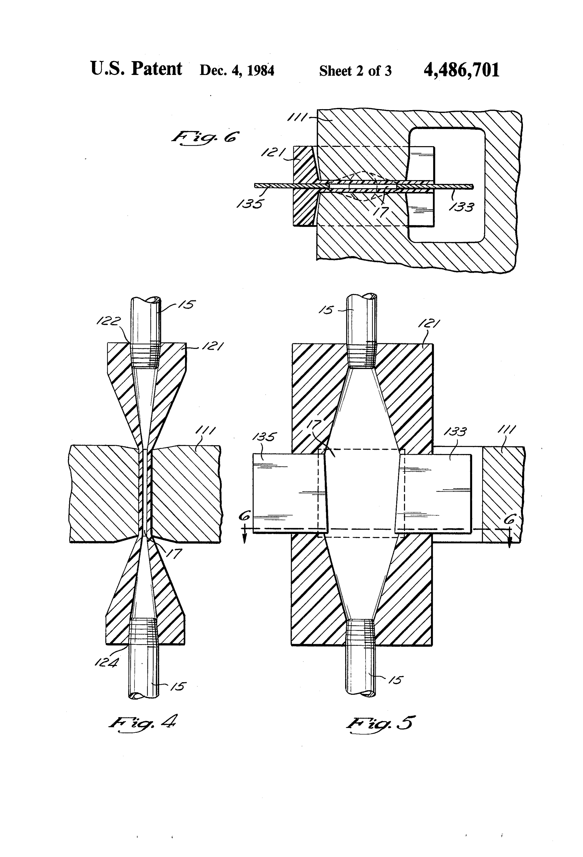
FIG. 4 is a cross-sectional view of the magnetohydro chemical energy. The pressure at which the gas genera dynamic generator used in the present invention taken tor must be capable of producing the gasses depends along line 4-4 of FIG. 2. upon the static prssure column 13 at gas injector 59 FIG. 5 is a cross-sectional view taken along line 5-5 caused by the column of mercury, since, to enter the of FIG. 2.
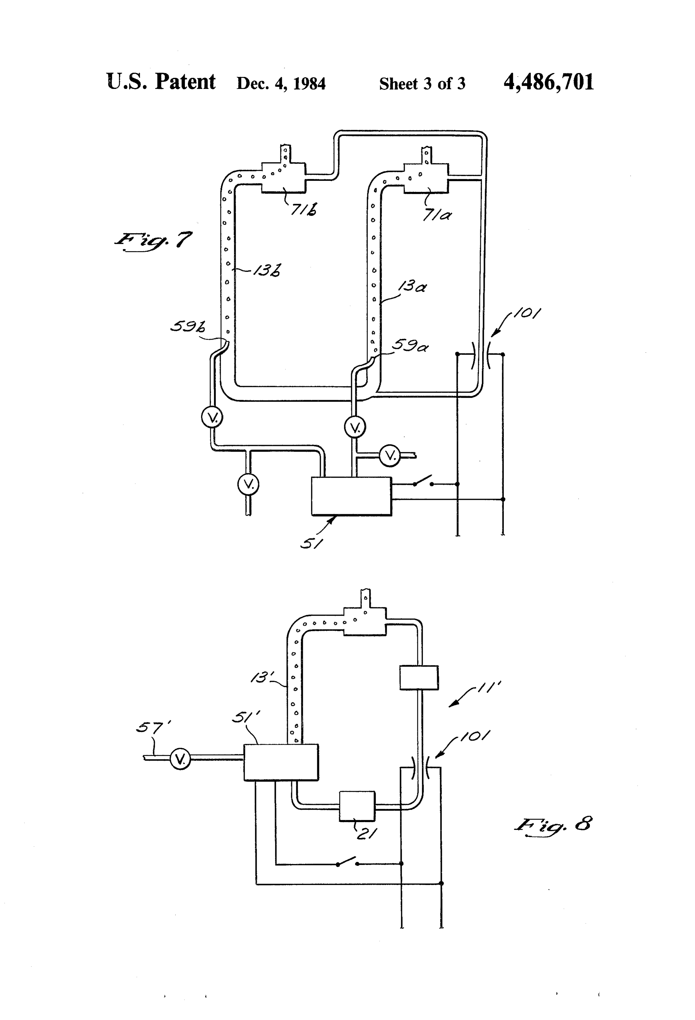
FIG. 6 is a cross-sectional view taken along line 6-6 column, the gas must be at a pressure at least as great as of FIG 2. that of that static pressure. This static pressure depends FIG. 7 is a schematic drawing of a first alternative on the height of the columns 13 and 15. For a small embodiment of the Thermal Energy Conversion Sys system with short columns, the gas genertor 51 need
only produce the gas at a pressure of a few pounds per square inch, while a gas generator coupled to a system
FIG. 8 is a schematic drawing of a second alternative using much embodiment of the Thermal Energy Conversion Sys taller columns needs to produce the gas at a tel. pressure on the order of a few hundred pounds per square inch.
DESCRIPTION OF THE PREFERRED Outlet 53 from the gas generator 51 is preferably
designed to keep the oxygen and hydrogen formed by
General System the gas generator separate, since together they form a The system of the present invention is shown sche pipes potentially exposive mixture. Outlet 53 branches into matically in FIG. 1. It comprises a fluid loop 11 that is part or55alland of 57. Pipe 55 leads to gas injector 59, so that the gasses generated by the electrolytic gas preferably closed, including first and second vertical 20 columns or legs 13 and 15 that are interconnected at the generator 51 may be injected into the first column 13. top and bottom. A conducting fluid, such as liquid mer Valve 63 is provided on pipe 55 to control the volume cury, flows through the loop 11. Liquid mercury is of gas entering the fluid flow loop. Pipe 57 leads to a advantageous becaause of its high electrical conductiv device for either storing or using the gasses. Advanta ity, high density, and low specific heat value, but other 25 geously, pipe 57 also keeps the gasses segregated, so electrically conductive fluids such as electrolytic solu that some of whichever of the gasses is injected into the tions may also be used, depending on cost consider column 13 may, if desired, also be diverted away from ations, equipment design or availability, or other fac the flow loop, and stored or used directly. Valve 65 on tors. On the second column 15 is an electric generator pipe 57 controls the volume of gas being diverted away 101, such as a magnetohydrodynamic generator (MHD) 30 from the flow loop. Adjusting the valves 63 and 65 101. Electrical leads 43 transmit the electric potential permits careful control of the portion of the gasses that generated by the MHD 101. goes directly to other uses and the portion introduced A source of thermal energy 21 is coupled to the loop into the fluid flow loop.
near the bottom of the first column 13. This source 21 Electrical leads 43 and 47 permit the power generated may be virtually any type of thermal energy source, 35 by the MHD 101 to be transferred to the electrolytic including a burner for fossil fuels or a heat exchanger gas generator 51. This feedback of the power generated drawing heat from a reservoir heated by either solar back into the system greatly increases the system's effi energy or geothermal energy. The temperature increase provided by the thermal energy source 21 depends ciency. ate the
Leads 45 permit power that is not used to oper gas generator 51 to be drawn off the system and upon the environment in which the system operates. 40 used for other purposes.
This temperature increase can range from 20 to 100 C.
or more, and is preferably at least 40 C. The MHD A heat exchanger 31 is connected to the loop near the The MHD 101, shown in FIGS. 2-6, includes a mag top of the second column 15 to draw heat from the net 111 with closely juxtaposed conducting fluid and transfer it to a heat sink, such as a 45 115 and 113, a nonferromagneticnorth and south poles block 121, and elec large body of cool water that is isolated from the sun, or trodes 133 and 135. Between the poles 115 and 113 is a some other low temperature body, which may be a body of ice if the system is used in a particularly cold throat section 17 of the block 121 (FIG. 4). This throat environment. section 17 is defined by two closely juxtaposed rectan A gas injector 59 for introducing gas into the system 50 gular walls 127 and 129 to allow a thin sheet of the loop is placed near the bottom of the first column 13. mercury to pass between the poles of the magnet. The Gas injector 59 is a gas nozzle outlet of conventional magnetic poles 113 and 115 are closely juxtaposed to design and is substantially centrally located in column maximize the intensity of the magnetic field across the 13. sheet of mercury passing through throat section 17. A gas separator 71 is coupled to the loop near the top 55 Block 121 further includes threaded openings 122 and of the first leg 13. Separator 71 may be of conventional 124 for receiving the ends of the tubular piping that design for drawing gas from a two-phase flow. Gas forms the remainder of the second column 15. The separator 71 permits the liquid mercury to continue passage through which the mercury passes is tapered flowing around the loop, while removing the gasses within the portions of the block 121 above and below introduced by gas injector 59 to be drawn off through 60 the throat section 17 to form a transition between the outlet 73. Outlet 73 is connected so that the gasses may tubular section of the second leg 15 and the thin throat be put to other uses, such as burned to produce heat or section 17. As shown in FIG. 2, the exterior of the block power, stored to be burned later, or used to synthesize 121 is also narrowed at throat section 17 So it will fit other fuels, such as methane or methanol. between the poles 113 and 115 of the magnet 111. An electrolytic gas generator 51 uses the electrical 65 Electrodes 133 and 135 (FIG. 5) are placed on either energy generated by the MHD 101 to electrolyze an side of this throat section 17 to tap the electric potential electrolyte, such as a solution of sulfuric acid (H2SO4) created between these two sides of the throat section. to generate hydrogen and oxygen gas, which contain These electrodes are advantageously shaped so that
Page 7
continuous contact between the electrodes and the mer solution of potassium carbonate may also be used to cury flowing through the throat section 17 is promoted. produce hydrogen and oxygen.
The throat section 17 is sized so that a venturi effect provides a ratio of approximately five to one between The Thermal Energy Source the speed of the mercury through the throat and the 5 The thermal energy source 21 may be one of a num speed through the other sections of the loop. ber of available apparatuses for transferring thermal The fluid flow passage through the MHD 101 must energy to the fluid circulating in the loop. The purpose be constructed to contain the mercury flowing through of the thermal energy source 21 is to increase the tem it, particularly at the threaded openings 122 and 124, perature of the liquid in column 13 relative to the liquid and at the points at which electrodes 133 and 135 enter O in column 15 so that a density differential is established throat section 17. But the passage is not subjected to the between the mercury in the two columns, causing a very high pressures that the MHD throat sections of convective flow of the fluid liquid around the loop. systems that use a plasma as the working fluid must Thus, the greater the temperature differential that can contain. be established, the greater the convective flow of the 15 liquid.
The Electrolytic Gas Generator Particularly appropriate as a thermal energy source, Electrolysis occurs when an electric current is passed in light of the interest in renewable resources, is a heat through an electrolyte between two electrodes, an exchanger Panels for drawing heat from a solar heated reservoir.
heating liquids such as water using solar anode and a cathode. Ions in the solution move to and from the anode and cathode so that material may be 20 energy are commercially available in many sizes from transported and deposited on one of the electrodes, new numerous sources, as are containers for storing the solar compounds may be formed, or gasses may be liberated. heated water. Heat exchangers are also readily available Certain electrolytes, such as sulfuric acid, sodium hy that can be coupled to the closed loop and are suitable for circulating the heated water from the reservoir and droxide, and potassium carbonate, when dissolved in 25 transferring its heat to the mercury circulating in the water, cause the water itself to decompose into its com ponent parts, hydrogen and oxygen, when a current is closed loop. Such apparatus can provide a 40' tempera ture differential, which is suitable for operation of the passed through the solution. System.
The amount of material orgas formed by the electrol Also appropriate would be the use of a heat ex ysis can be found using Faraday's Laws, which say that 30 changer circulating geothermally heated water. Geo (1) the amount of chemical change produced by an thermally heated water often is at a much higher tem electric current is proportional to the quantity of elec perature than solar heated water would be, on the order tricity and (2) the amounts of different substances liber ated by a given quantity of electricity are proportional of 120°-180° C., and thus would be able to produce a greater temperature differential between the mercury in to their chemical equivalent weights. (Equivalent 35 column 13 and the merciry in column 15. This increased weight=atomic weight divided by valence change.) temperature differential is advantageous in that the Thus, the amount of material or gas produced is propor density differential between the mercury in the two tional to the current passed through the solution. When columns is greater, and consequently the convective water is electrolyzed, the volume of hydrogen and oxy flow of the mercury is increased. But, the availability of gen produced is proportional to the current passed geothermal energy is limited.
through the solution. In addition to the sources of thermal energy just An example of a simple electrolytic gas generator discussed, a fossil fuel burner of conventional design that may be installed in the present system as gas gener may be used as thermal energy source 21 to directly ator 51 is a fully charged automobile storage battery heat the circulating mercury.
comprising lead plates immersed in a solution of sulfuric 45 Since the important consideration for operation of acid. As current is passed through the solution in the the system is the temperature differential between the cell the water in the solution is dissociated into hydro liquid in the two columns 13 and 15, heat exchanger 31 gen and oxygen. The hydrogen is given off at one of the must be connected to a heat sink capable of absorbing electrodes, and the oxygen at the other. As the electrol from the liquid the heat transferred to it by thermal ysis continues and the water in the electrolyte solution 50 energy source 21. In a system located in a temperature is dissociated into its component parts to form the gas climate, this is most effectively done by circulating in ses, the water must be replaced, but the acid itself re the heat exchanger cool water drawn from a large reser mains in the solution. voir kept cool by isolating it from exposure to the sun. The gasses produced should be kept separate, since, In a colder climate, a large body of ice may be used, in the case of hydrogen and oxygen, the two gasses 55 which would permit the temperature of the mercury to together form an explosive mixture. This separation can be reduced to 0°C., or perhaps. lower. be maintained by placing a membrane between the elec Operation of the System trodes.
Since the amount of gas produced is proportional to In operation, thermal energy is added by heat source the current, but not the pressure under which the cell 60 21 to the conducting fluid in the first column 13 to operates (except at the extremes), the gasses may be lower the density of the fluid in that column, thereby produced at relatively high pressures with negligible inducing a convective flow of the mercury. The heat so increases in the power consumed. introduced into the conducting fluid is removed by the Other types of electrolytic cells may also be used as heat exchanger 31 at the top of the second column 15 to gas generator 51. A cell comprising a nickle anode and 65 ensure the continuation of the temperature differential iron cathode immersed in a solution of sodium hydrox (and the density differential) between the mercury in ide in water produces oxygen at the anode and hydro the first and second columns. As the fluid flows down gen at the cathodes. Nickel electrodes immersed in a ward in the second column, it flows through the throat
Page 8
section 17 of the MHD 101 in a direction perpendicular Each cycle of flow (once around the loop) extracts an to the magnetic field established by the magnet 111. amount of energy proportional to the weight difference This flow, by reason of Faraday's Laws, creates an between the two columns (represented by the equation electric potential between the sides of the throat section 5 hE-dWXh, is the in which dW is the difference in weight and height of the column). The amount of power 17, which is tapped by the electrodes 133 and 135. This that can be obtained from the system depends upon the purely temperature-induced convective flow through the MHD will generate a very low power output. The speed or time it takes to complete the stroke, i.e., the power output is low due to the low velocity of the rate at which the work is done. Thus, the power is given electrically conducting fluid through the MHD. by the equation P=d WXy, in which V is the speed of The electric potential is produced in the following 10 the fluid flow.
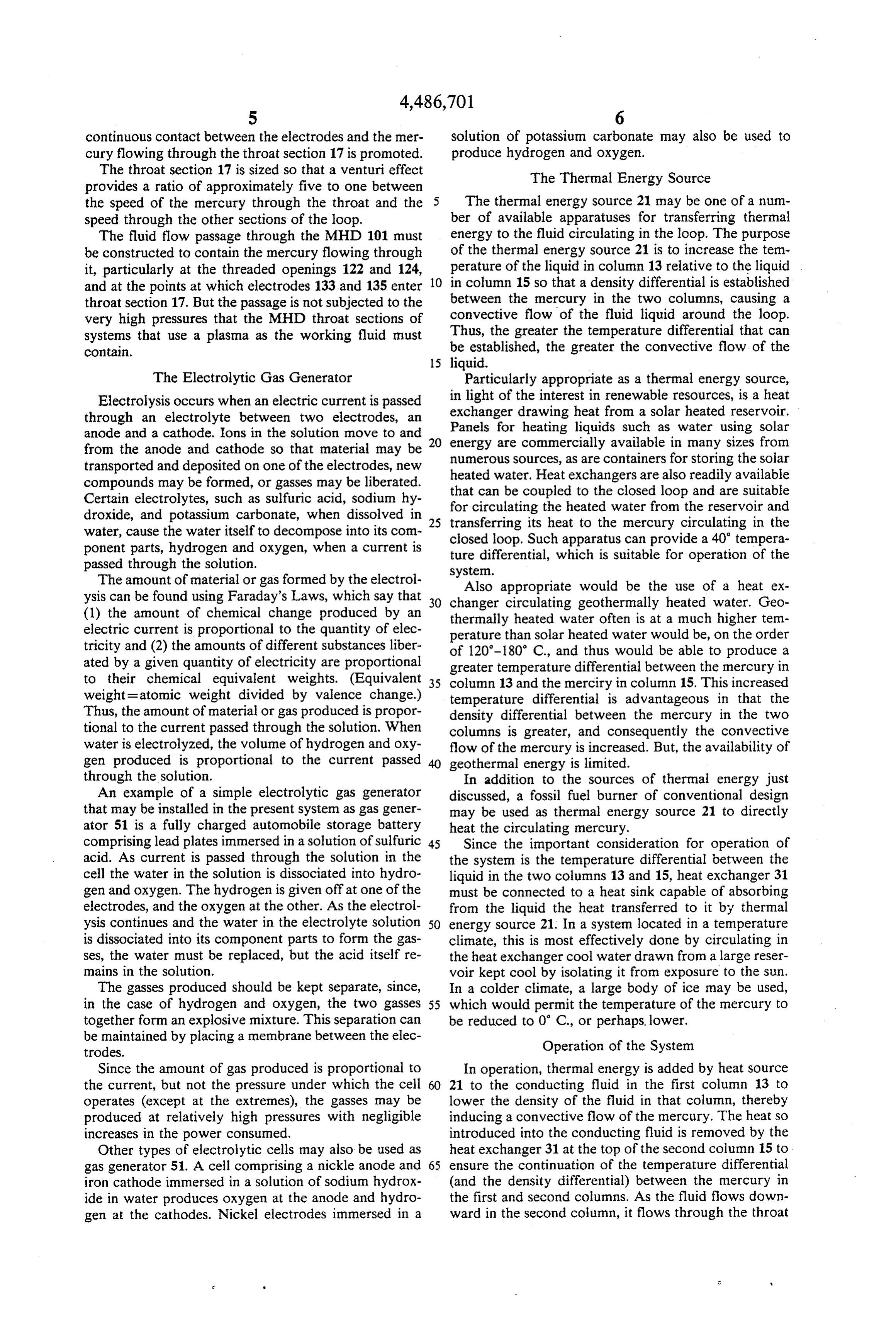
manner: When a sheet of conducting material, e.g. mer As the system continues to operate, the MHD 101 cury, is passed through a magnetic field that is perpen may generate more power than is needed to operate the dicular to the direction in which the conducting mate electrolytic gas generator 51. When this occurs, electri rial is moving, an electric potential develops between 15 cal leads 45 may be attached to an external load suitable points on the sheet of conductive material that lie on an for using this excess power. Alternately, electrical leads axis perpendicular to both the direction of movement of 45 may be connected to a battery to store the power for the conductive sheet and the direction of the magnetic later use. Accordingly, the system may be advanta field. geously used to convert the thermal energy supplied by As the conductive fluid flows with velocity V 20 thermal energy source 21 to both chemical energy in through the perpendicular magnetic field B, a force is the form of gasses and electrical energy. exerted on each charge carrier in a third, mutually per ALTERNATIVE EMBODIMENTS pendicular direction. This force F is given by the vector equation: General System 25 Alternatively to using a single upflowing column 13 in the MHD loop 11, two or more columns 13a and 13b in which q is the charge of each charge carrier. The may be used, as shown in FIG. 7. In this embodiment, electric field intensity (E) resulting from this force is one of the gasses produced by electrolytic gas generator given by the vector equation: 51, for example the oxygen may be injected into column 30 13a and the other gas, the hydrogen, may be injected into column 13b. In this way, both the gasses produced may be used to supplement the convective flow, while
This electric field yields an electric potential between keeping the gasses separate. Since both gasses produced two sides of the channel through which the conductor by the gas generator are used, the utility of the feedback flows. This potential is: 35 of the electrical energy generated by the MHD 101 is enhanced. This embodiment requires at least two gas separators 71a and 71b (one to separate each gas out of in which L represents the width of the sheet of conduc the flow), and a gas injector 59a and 59b for each col umn 13a and 13b.
In the MHD loop, flow equilibrium is reached when The Electrolytic Gas Generator the electromotive force so generated equals the force As an alternative to using a liquid metal such as mer driving the fluid flow, the differences in the weight of cury in the MHD loop 11 and electrolyzing a separate the mercury in the two columns. electrolyte in gas generator 51, an electrolyte may be By using the electric power generated by the MHD 45 circulated through the MHD loop 11' (FIG. 8) and 101 to electrolyze a second fluid in gas generator 51 and passed through electrolytic gas generator 51' so that the introduce the gasses so generated into the rising first MHD working fluid itself is electrolyzed. From gas column 13, the efficiency of the system can be greatly generator 51 part or all of the gasses may be injected increased due to the increased rate of flow of the electri cally conducting fluid through the MHD. When the 50 into the column 13". Pipe 57" allows whatever of the gasses produced by the electrolytic gas generator 51 are gasses are not injected into column 13' to be diverted introduced into the first column 13, the density and andI claim:put directly to use.
weight of the mercury in that column is substantially decreased, which increases the density and weight dif chemical1. An apparatus for converting thermal energy into ferentials between the fluid in the first column 13 and 55 energy, comprising: the fluid in the second column 15. This increased differ (1) a closed fluid loop through which flows an electri ential greatly enhances the convective flow of the mer cally conducting liquid, said loop comprising: cury around the loop, increasing the rate of flow of the (a) a first substantially vertical column; conductive fluid through the throat 17 of the MHD (b) a second substantially vertical column; section of the loop. As this flow through the throat 60 (c) interconnection means between the top of said section is increased, so is the power produced by the first column and the top of said second column; and MHD. This increase continues until a new flow equilib (d) interconnection means between the bottom of said rium is reached. first column and the bottom of said second column. The gasses introduced into the loop, which contain (2) means for creating a temperature differential be chemical energy, are separated from the conducting 65 tween the portions of said liquid in each column by fluid at the top of the loop by the gas separator 71 and heating the portion of said liquid in said first column may be put to any of a number of uses, as mentioned and cooling the portion of said liquid in said second above. column to form a density differential in said liquid
Page 9
and establish a convective flow of said liquid through portion of said electrical energy to electrolyze a said loop; portion of said conducting liquid to form a gas, said (3) a magnetohydrodynamic generator coupled to said gas containing said chemical energy; loop for generating electrical energy from said flow (b) means for introducing a portion of said gas into ing liquid, the amount of electrical energy generated said first column to decrease the density of the being proportional to the velocity of the said liquid; portion of said liquid in said first column and in and crease the density differential between the portions (4) means for supplementing said convective flow to of said liquid in each column; and increase the electrical energy generated by said mag (c) means for removing said gas near the top of said netohydrodynamic generator by increasing the den 10 first column.
sity differential between the liquid in each of said 5. An apparatus for efficiently converting thermal columns, comprising: energy into an alternate form of energy, comprising: (a) an electrolytic gas generator coupled to said man (1) A fluid conduit through which flows a fluid, getohydrodynamic generator for using at least a wherein said conduit comprises:
portion of said electrical energy to electrolyze a 5 (a) a first, substantially vertical, leg; second liquid to form a gas, said gas containing said (b) a second, substantially vertical, leg; chemical energy; (c) first communication means between the top of (b) means for introducing a portion of said gas into said first leg and the top of said second leg; and said first column to decrease the density of the (d) second communication means between the bot portion of said liquid in said first column and in tom of said first leg and the bottom of said second crease the density differential between the portions leg;
of said liquid in each column; and (c) means for removing said gas near the top of said (2)tofirst means for adding thermal energy to said fluid, create a flow of said fluid, wherein:
first column.
2. The apparatus of claim 1, wherein said magnetohy 25 (a) said fluid flows upward through said first leg; and drodynamic generator comprises: (b) said fluid flows downwardly through said second leg;
(1) a throat segment of said second vertical column (3) second means coupled to said conduit near the bot through which said liquid flows; tom of said second leg for generating electrical en (2) a magnet creating a magnetic field perpendicular to said flow of said liquid through said throat segment so 30 (4) thirdfrom ergy said flowing fluid;
means coupled to said second means for using that as said liquid flows through said throat segment at least a portion of said electrical energy to form a an electric potential is created between two sides of gas, said gas containing chemical energy; and said throat segment; and (3) electrodes coupled to said throat segment, said elec (5)least fourth means for introducing into said conduit at a portion of the gas formed by said third means trodes tapping said electric potential. 35 so that the rate of flow of said fluid is increased.
3. The apparatus of claim 2, wherein said throat seg 6. The apparatus defined in claim 5 wherein: ment is of smaller cross sectional area than another section of said second vertical column to provide a (1)gas said third means for forming a gas is an electrolytic generator that electrolyzes a second fluid; and venturi effect to said flow.
4. An apparatus for converting thermal energy into (2) said fourth means for using said gas comprises means chemical energy, comprising: coupled to said conduit and to said third means for (1) a closed fluid loop through which flows an electri introducing said gas into said first leg. cally conducting liquid, said loop comprising: 7. The apparatus defined in claim 5, wherein: (a) a first substantially vertical column; (1) said fluid is an electrolyte;
(b) a second substantially vertical column; 45 (2) said third means for forming a gas is an electro (c) interconnection means between the top of said lytic gas generator that electrolyzes a portion of first column and the top of said second column; and said fluid; and (d) interconnection means between the bottom of said (3) said fourth means for using said gas comprises means first column and the bottom of said second column. coupled to said conduit for introducing said gas into (2) means for creating a temperature differential be 50 said first leg.
tween the portions of said liquid in each column by 8. The apparatus defined in claim 6 or 7, additionally heating the portion of said liquid in said first column comprising fifth means coupled to said conduit for re and cooling the portion of said liquid in said second moving said gas from said conduit wherein said fifth column to form a density differential in said liquid means is coupled to said conduit near the top of said first and establish a convective flow of said liquid through 55 leg.
said loop; 9. The apparatus defined in claim 5, additionally com (3) a magnetohydrodynamic generator coupled to said prising means for removing said thermal energy from loop for generating electrical energy from said flow said fluid, wherein:
ing liquid, the amount of electrical energy generated (1) said first means for adding thermal energy is coupled being proportional to the velocity of the said liquid; to said conduit on said first leg; and and (2) said means for removing thermal energy is coupled (4) means for supplementing said convective flow to to said conduit near top of said second leg. increase the electrical energy generated by said mag 10. The apparatus defined in claim 9, wherein said netohydrodynamic generator by increasing the den means for removing said thermal energy comprises: sity differential between the liquid in each of said 65 (1) a heat exchanger coupled to said conduit; and columns, comprising: (2) a heat sink interconnected with said heat exchanger, (a) an electrolytic gas generator coupled to said mag suitable for absorbing the heat removed from Said netohydrodynamic generator for using at least a fluid by said heat exchanger.
Page 10
11. The apparatus defined in claim 5, wherein said 13. The apparatus defined in claim 5, wherein: first means for adding thermal energy comprises: (1) said third means for forming a gas is an electrolytic (1) a heat exchanger coupled to said conduit near the gas generator that produces one or more gasses; bottom of said first leg; and (2) said conduit additionally comprises a third, substan (2) a heat source interconnected with said heat ex- 5 tially vertical, leg in which said fluid flows upwardly; changer suitable for supplying thermal energy to said (3) said fourth means is suitable for introducing some of heat exchanger. said gasses produced by said gas generator into said 12. The apparatus defined in claim 11, wherein: first leg; and (1) said heat source comprises a quantity of a third fluid; (4) said fourth means is suitable for introducing an addi and 10 tional portion of said gasses produced by said gas (2) said quantity of a third liquid is heated by solar generator into said third leg. radiation. : k k
Provenance
- Collection
- Cited prior art
- Original PDF
- patentimages.storage.googleapis.com →
- Filed
- 1982-01-25
- Pages
- 10
- Method
- pdftotext (the PDF's own text layer) + pdftoppm 300dpi page scans
- Source
- Google Patents bibliographic record
- Granted
- 1984-12-04
- Inventors
- John H. Cover
- Transcribed from
- patentimages.storage.googleapis.com →