patent · US3616334
Electrically and chemically coupled power generator and hydrogen generator
26 October 1971
Page 1 — bibliographic record
United States Patent (11) 3,616,334 72 inventors Walter W. Aker 56 References Cited Schenectady; UNITED STATES PATENTS
Dale H. Brown, Scotia; Henry S. Spacil,
Schenectady; Donald W. White, Burnt 3,400,054 9, 1968 Ruka et al..................... 204/1.1 Hills, all of N.Y. 3,459,953 8/1969 Hughes et al................. 204/129 21) Appl. No. 742,699 Primary Examiner-T. Tung 22 Filed July 5, 1968 Attorneys--Richard R. Brainard, Paul A. Frank, Charles T. 45 Patented Oct. 26, 1971 Watts, Leo I. Ma Lossi, Frank L. Neuhauser, Oscar B. , 73) Assignee General Electric Company Waddell and Melvin M. Goldenberg
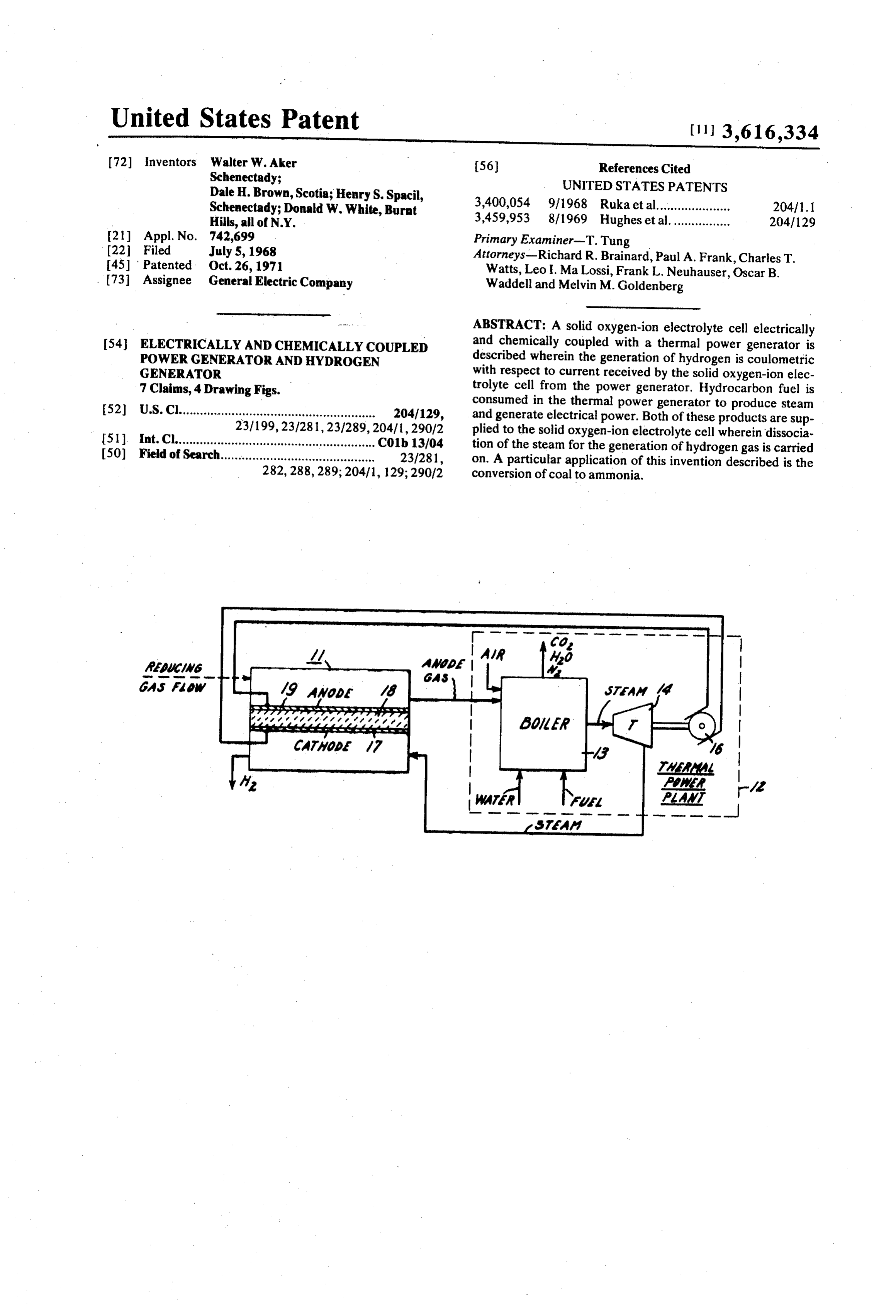
ABSTRACT: A solid oxygen-ion electrolyte cell electrically 54 ELECTRICALLY AND CHEMICALLY COUPLED and chemically coupled with a thermal power generator is POWER GENERATOR AND HYDROGEN described wherein the generation of hydrogen is coulometric GENERATOR with respect to current received by the solid oxygen-ion elec 7 Claims, 4 Drawing Figs. trolyte cell from the power generator. Hydrocarbon fuel is consumed in the thermal power generator to produce steam (52) U.S.C........................................................ 204/129, and generate electrical power. Both of these products are sup 231199,231281,231289, 204/1,290/2 plied to the solid oxygen-ion electrolyte cell wherein dissocia 5ll int. Cl......................................................... C01b 13/04 tion of the steam for the generation of hydrogen gas is carried (50) Field of Search............................................ 23/281, on. A particular application of this invention described is the 282,288, 289; 204/1, 129; 290/2 conversion of coal to ammonia.
ow is war m wi
Ms AAAW 49 Awaba 4
Rawa warn towawararu, Vasave as a rare is av
Page 2
Drawing sheet — no readable text.
Page 3
Drawing sheet — no readable text.
Page 4
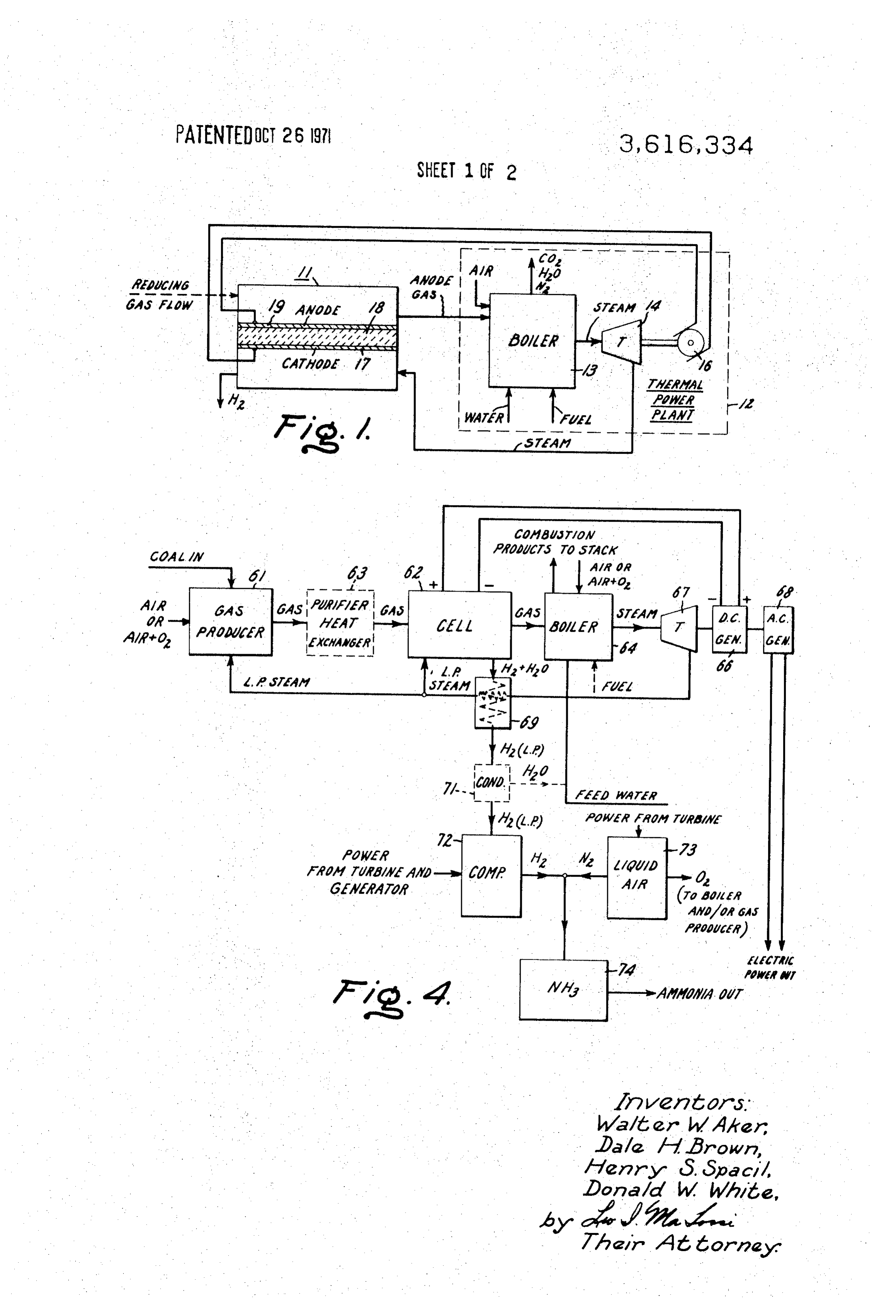
ELECTRICALLY AND CHEMICALLY COUPLEO POWER Hydrocarbon fuels, such as powdered coal or gas, are ad GENERATOR AND HYDROGENGENERATOR mitted to and burned in boiler 13 in the presence of air to con BACKGROUND OF THE INVENTION vert incoming water to high-pressure steam. Depending upon the particular construction and method of operation of
Solid oxygen-ion electrolyte fuel cell structures for opera- 5 hydrogen generator 11, the gas from the anode element is con tion at elevated temperatures are broadly old. Such fuel cells veyed to boiler 13 and will either be oxygen (which is added to employ in combination a solid oxygen-ion electrolyte layer air input to boiler 13) or a mixture of gases comprising CO, having electrodes at opposite faces thereof, fuel and oxygen H, N, CO, and HO, which contributes residual combustible supplies in communication with the respective electrodes and O heating value to the boiler in addition to providing sensible electrical leads connected to the respective electrodes. heat.
Such fuel cell structures have been used to generate low The specific use of solid oxygen-ion electrolyte cell struc voltage direct current power and have also been used to detect tures in combination with a coal gasifier for the hydrogenation the presence of oxygen. When operated in reverse (electrical of coal is described and claimed in U.S. Pat. application Ser. No. 742,824 Spacil filed July 5, 1968. Also, particular con power supplied to the electrodes) such constructions will is struction function as oxygen pumps or oxygen concentrators. In the and operation of a solid oxygen-ion electrolyte cell latter application an electrical coupling between the solid ox for the generation of hydrogen is described and claimed in ygen-ion electrolyte cell and a source of electrical power is U.S. Pat. application Ser. No. 742,653 filed July 5, 1968. required. However, no simultaneous chemical coupling or Both of the aforementioned applications are assigned to the operative chemical interdependence between these structures 20 assignee of the instant application and are incorporated by appears to have been proposed. reference.
The generation of hydrogen in solid oxygen-ion electrolyte
SUMMARY OF THE INVENTION cell 11 involves the phenomenon of dissociation, rather than It has been found that by employing solid oxygen-ion elec of electrolysis, because there are no ions present in solution as trolyte cells operating at elevated temperatures, preferably 25 would be the case in electrolysis. Water is converted to high over 800° C. for the generation of hydrogen by the dissocia pressure steam in boiler 13 for the operation of turbine 14. tion of water vapor and by both chemically and electrically The low-pressure steam leaving turbine 14 is brought into con coupling such a hydrogen generation equipment to a thermal tact with cathode 17 of cell 11, which is heated to some power plant, the very interdependence of the components in elevated operating temperature (preferably in excess of 800' such a combination is particularly attractive economically and 30 C.). Cell heating is usually accomplished by the Joulean heat ing of the cell electrolyte 18 due to the passage of the dis provides a flexible base system to which various chemical sociating current therethrough from anode 19 to cathode 17 syntheses employing the hydrogen output of the base system may be effectively added. plus some other form of heating, if required, such as electrical Thus, fuel is burned in the boiler of a power generator and 35 resistance heating or combustion of fuel. incoming feed water to the boiler is converted to steam. This as shown with thepower
Direct current from generator 16 is applied to cell 11 path of electrons flowing from generator 16 steam is used to drive a turbogenerator in the conventional manner to produce power. This power from the generator is to cathode 17 and from anode 19 back to generator 16. At cathode 17, the low-pressure steam from turbine 14 is dis used to operate solid oxygen-ion electrolyte cell structures, sociated into hydrogen and oxygen and each atom of oxygen which is not unusual, but what is unique is that these cell struc-40 accepts two tures are used to dissociate the low-pressure steam output of ion electrons to become an oxygen-ion Each oxygen the turbogenerator yielding hydrogen gas such that the is then transported across solid oxygen-ion electrolyte generation of hydrogen therefrom is coulometric with respect layer 18 to anode 19. At anode 19, the oxygen-ions release to current received from the turbogenerator. Also gas from electrons, which as has been noted above return to generator the anode elements of these cell structures is fed to the boiler 45 16Ifmaking oxygen atoms available at anode 19. both to enter into the combustion process and to utilize the into oxygen the gas is a desired by product, there is no gas input anode region from the exterior of the cell and the sensible heat therein. Additional interdependence may be structure may be employed as described above with the ox used to advantage, for example, by employing power from the ygen produced being used to enrich the boiler combustion air.
turbine to liquefy air for the production of nitrogen, which is Optionally, combined with the hydrogen output from the solid oxygen-ion 50 gases, for example however, a reducing gas or mixture of reducing electrolyte cell structures to synthesize ammonia. a COIH mixture, may be caused to flow into contact with anode 19, whereby the oxygen produced at
BRIEF DESCRIPTION OF THE DRAWING the anode becomes chemically combined with the reducing gas or gases as it evolves. A suitable reducing gas mixture may
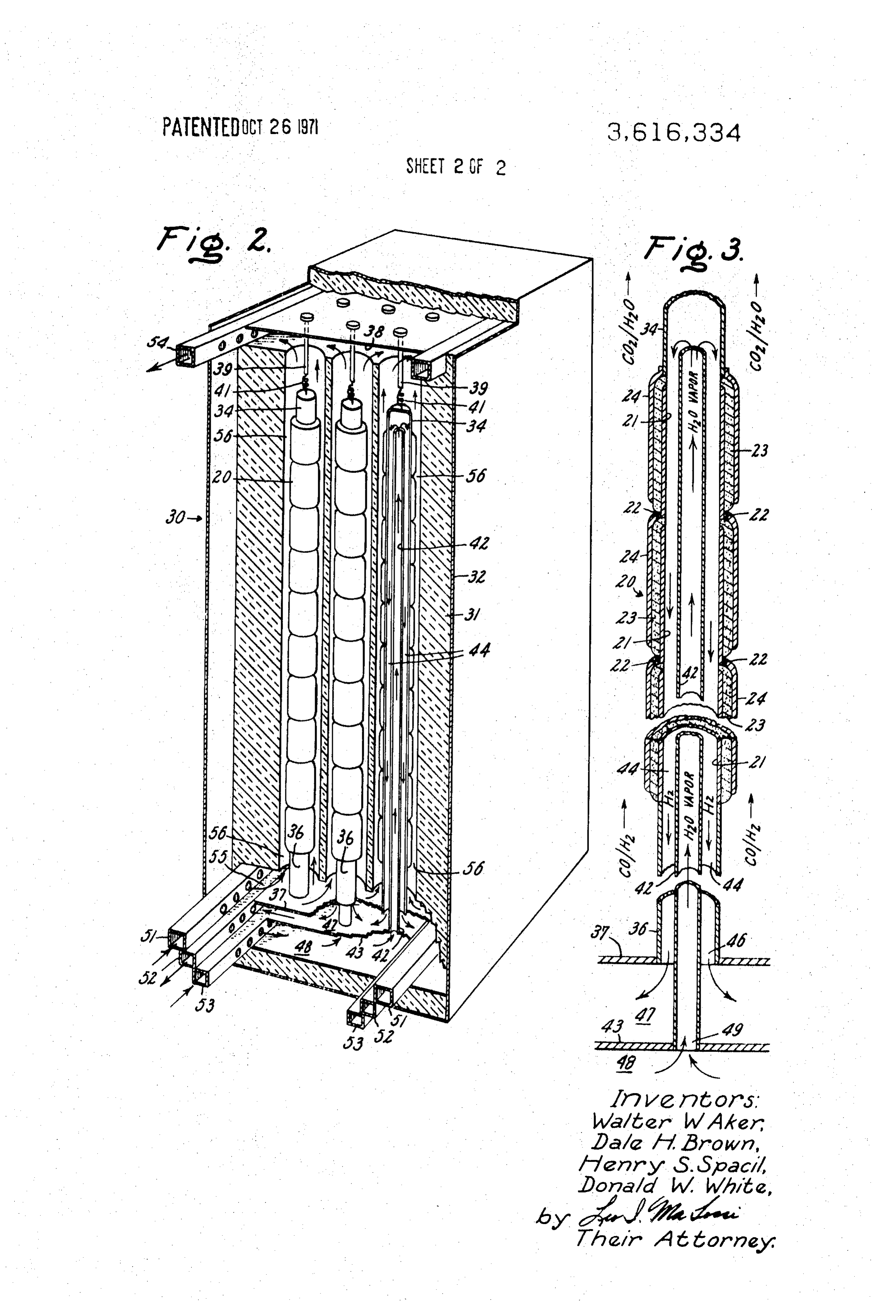
The exact nature of this invention as well as objects and ad be produced, for example, by the partial oxidation of a vantages thereof will be readily apparent from consideration 55 hydrocarbon fuel in air in the presence of water vapor. By sup of the following specification relating to the annexed drawing plying reducing gas to the anodic electrode 19, the voltage of in which: the solid oxygen-ion electrolyte cell 11 is reduced by an FIG. 1 is a schematic representation of the base system amount in the order from 0.6 to 1.2 volts. This behavior is showing the chemical and electrical interdependence between 60 known as "depolarization'. In effect, the electrical power the hydrogen generator and the thermal power generator, required from generator 16 for the dissociation of steam in FIG. 2 is a perspective view, partially cut away, of an exem cell plary steam dissociation module housing a hexagonal array of of the11 reducing is reduced sharply and the heat produced by oxidation gas components at the anode contributes to multicell stacks of solid oxygen-ion electrolyte cells, the operating temperature level. Any unoxidized reducing gas FIG.3 is an enlarged view shown in cross section of one of 65 remaining in the outgoing anode gas flow will contribute to the the solid electrolyte cell stacks employed in FIG. 3, and
FIG. 4 is a flow diagram showing the use of a base system in fuel value in boiler 13 in addition to providing sensible heat to the boiler.
an arrangement for the synthesis of ammonia. The construction of an exemplary solid oxygen-ion elec DESCRIPTION OF THE PREFERREDEMBODEMENT 70 trolyte cell is described in detail in connection with FIGS. 2 and 3, however, in general, the construction of the cell stack
The flow sheet of FIG. 1 schematically represents the com shown in FIG. 3 is substantially in accordance with the disclo bination of a hydrogen generator, solid oxygen-ion electrolyte sure in U.S. Pat. application Ser. No. 465,624-White, filed cell 11, and thermal power plant 12 comprising boiler 13 and June 21, 1965, now U.S. Pat. No. 3,402,230. Various elec a turbogenerator (steam turbine 14 and direct current genera trode and electrolyte constructions for use in such a cell stack tor 16). 75 are described in the following patent applications: Ser. No.
Page 5
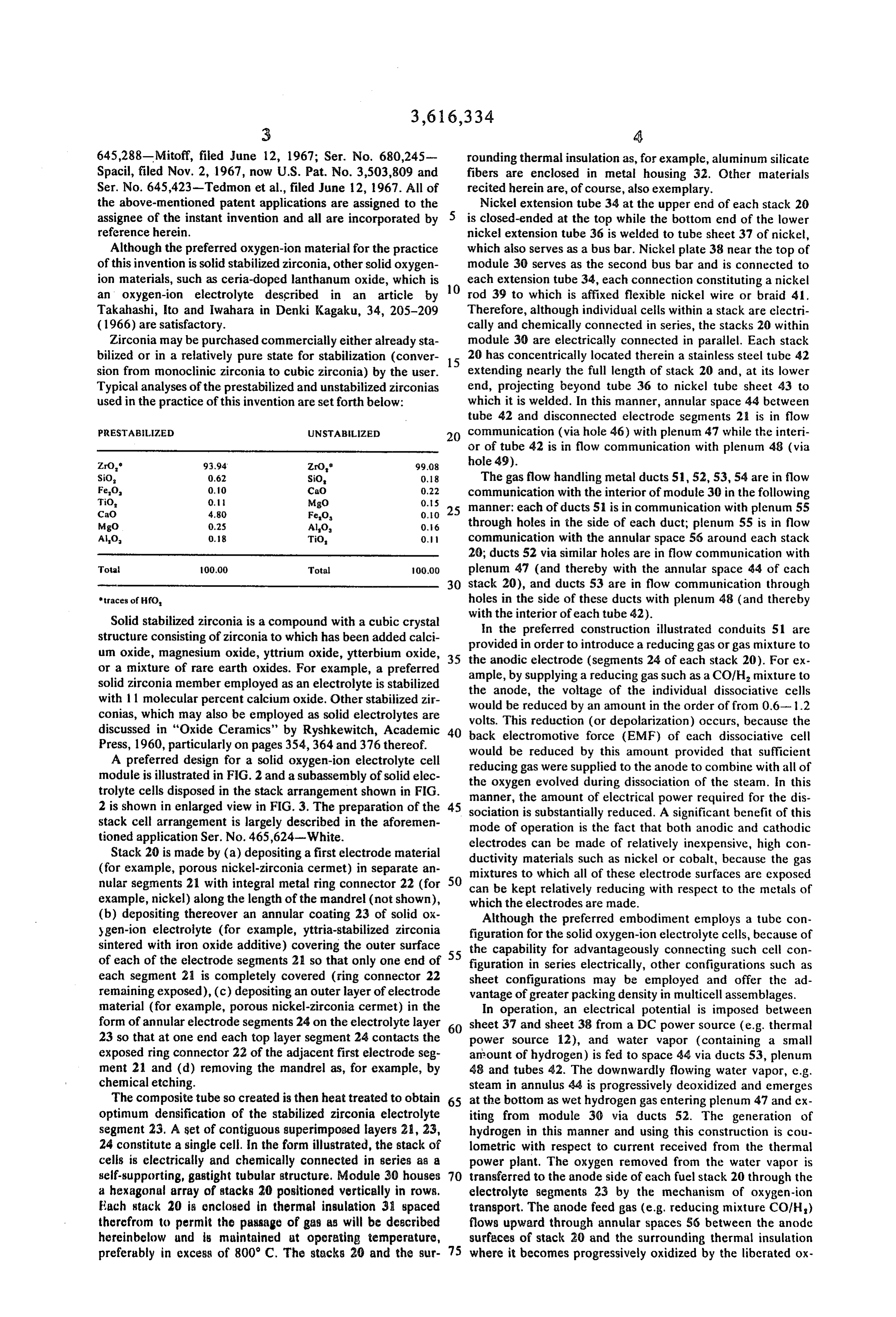
645,288-Mitoff, filed June 12, 1967; Ser. No. 680,245 rounding thermal insulation as, for example, aluminum silicate Spacil, filed Nov. 2, 1967, now U.S. Pat. No. 3,503,809 and fibers are enclosed in metal housing 32. Other materials Ser. No. 645,423-Tedmon et al., filed June 12, 1967. All of recited herein are, of course, also exemplary. the above-mentioned patent applications are assigned to the Nickel extension tube 34 at the upper end of each stack 20 assignee of the instant invention and all are incorporated by is closed-ended at the top while the bottom end of the lower reference herein. nickel extension tube 36 is welded to tube sheet 37 of nickel, Although the preferred oxygen-ion material for the practice which also serves as a bus bar. Nickel plate 38 near the top of of this invention is solid stabilized zirconia, other solid oxygen module 30 serves as the second bus bar and is connected to ion materials, such as ceria-doped lanthanum oxide, which is O each extension tube 34, each connection constituting a nickel an oxygen-ion electrolyte described in an article by rod 39 to which is affixed flexible nickel wire or braid 41. Takahashi, to and Iwahara in Denki Kagaku, 34, 205-209 Therefore, although individual cells within a stack are electri (1966) are satisfactory. cally and chemically connected in series, the stacks 20 within Zirconia may be purchased commercially either already sta module 30 are electrically connected in parallel. Each stack bilized or in a relatively pure state for stabilization (conver 15 20 has concentrically located therein a stainless steel tube 42 sion from monoclinic zirconia to cubic zirconia) by the user. extending nearly the full length of stack 20 and, at its lower Typical analyses of the prestabilized and unstabilized zirconias end, projecting beyond tube 36 to nickel tube sheet 43 to used in the practice of this invention are set forth below: which it is welded. In this manner, annular space 44 between tube 42 and disconnected electrode segments 2 is in flow
PRESTABLIZED UNSTABLIZED 20 communication (via hole 46) with plenum 47 while the interi or of tube 42 is in flow communication with plenum 48 (via
Zro, 93.94 ZrO" 99.08 hole 49).
SiO, 0.62 SiO, 0.18 The gas flow handling metal ducts 51, 52, 53, 54 are in flow Feo,
TiO,
CaO
MgO)
communication with the interior of module 30 in the following
CaO 4.80 Fe0. 0.0 25 manner: each of ducts 51 is in communication with plenum 55 Migo 0.2S AlO 0.6 through holes in the side of each duct; plenum 55 is in flow AlO. 0.18 TiO, 0.1 communication with the annular space 56 around each stack 20; ducts 52 via similar holes are in flow communication with
Total 100.00 Total 100.00 plenum 47 (and thereby with the annular space 44 of cach 30 stack 20), and ducts 53 are in flow communication through traces of Hfo, holes in the side of these ducts with plenum 48 (and thereby Solid stabilized zirconia is a compound with a cubic crystal with the interior of each tube 42).
In the preferred construction illustrated conduits 51 are structure consisting of zirconia to which has been added calci provided um oxide, magnesium oxide, yttrium oxide, ytterbium oxide, 35 the anodicinelectrode order to introduce a reducing gas orgas mixture to (segments 24 of each stack 20). For ex or a mixture of rare earth oxides. For example, a preferred ample, by supplying a reducing gas such as a COIH mixture to solid zirconia member employed as an electrolyte is stabilized the anode, the voltage of the individual dissociative cells with 11 molecular percent calcium oxide. Other stabilized zir would be reduced by an amount in the order of from 0.6-1.2 conias, which may also be employed as solid electrolytes are volts. This reduction (or depolarization) occurs, because the discussed in “Oxide Ceramics' by Ryshkewitch, Academic 40 back electromotive force (EMF) of each dissociative cell Press, 1960, particularly on pages 354, 364 and 376 thereof.
A preferred design for a solid oxygen-ion electrolyte cell would be reduced by this amount provided that sufficient reducing gas were supplied to the anode to combine with all of module is illustrated in FIG. 2 and a subassembly of solid elec trolyte cells disposed in the stack arrangement shown in FIG. the oxygen evolved during dissociation of the steam. In this 2 is shown in enlarged view in FIG. 3. The preparation of the 45 sociationthe manner, amount of electrical power required for the dis is substantially reduced. A significant benefit of this stack cell arrangement is largely described in the aforemen mode of operation is the fact that both anodic and cathodic tioned application Ser. No. 465,624-White. electrodes can be made of relatively inexpensive, high con Stack 20 is made by (a) depositing a first electrode material ductivity materials such as nickel or cobalt, because the gas (for example, porous nickel-zirconia cermet) in separate an mixtures to which all of these electrode surfaces are exposed nular segments 21 with integral metal ring connector 22 (for can50 be kept relatively reducing with respect to the metals of example, nickel) along the length of the mandrel (not shown), which the electrodes are made.
(b) depositing thereover an annular coating 23 of solid ox Although the preferred embodiment employs a tube con ygen-ion electrolyte (for example, yttria-stabilized zirconia figuration for the solid oxygen-ion electrolyte cells, because of sintered with iron oxide additive) covering the outer surface 55 the capability for advantageously connecting such cell con of each of the electrode segments 21 so that only one end of figuration in series electrically, other configurations such as each segment 21 is completely covered (ring connector 22 sheet configurations may be employed and offer the ad remaining exposed), (c) depositing an outer layer of electrode vantage of greater packing density in multicell assemblages. material (for example, porous nickel-zirconia cermet) in the In operation, an electrical potential is imposed between form of annular electrode segments 24 on the electrolyte layer 60 sheet 37 and sheet 38 from a DC power source (e.g. thermal 23 so that at one end each top layer segment 24 contacts the power source 12), and water vapor (containing a small exposed ring connector 22 of the adjacent first electrode seg amount of hydrogen) is fed to space 44 via ducts 53, plenum ment 21 and (d) removing the mandrel as, for example, by 48 and tubes 42. The downwardly flowing water vapor, e.g. chemical etching. steam in annulus 44 is progressively deoxidized and emerges The composite tube so created is then heat treated to obtain 65 at the bottom as wet hydrogen gas entering plenum 47 and ex optimum densification of the stabilized zirconia electrolyte iting from module 30 via ducts 52. The generation of segment 23. A set of contiguous superimposed layers 21, 23, hydrogen in this manner and using this construction is cou 24 constitute a single cell. In the form illustrated, the stack of lometric with respect to current received from the thermal cells is electrically and chemically connected in series as a power plant. The oxygen removed from the water vapor is self-supporting, gastight tubular structure. Module 30 houses 70 transferred to the anode side of each fuel stack 20 through the a hexagonal array of stacks 20 positioned vertically in rows. electrolyte segments 23 by the mechanism of oxygen-ion Each stack 20 is enclosed in thermal insulation 31 spaced transport. The anode feed gas (e.g. reducing mixture CO/H) therefrom to permit the passage of gas as will be described flows upward through annular spaces S6 between the anode hereinbelow and is maintained at operating temperature, surfaces of stack 20 and the surrounding thermal insulation preferably in excess of 800° C. The stacks 20 and the sur 75 where it becomes progressively oxidized by the liberated ox
Page 6
ygen gas so that the spent anode gas, which finally flows Effluent low-pressure steam from turbine 67 is conducted to through passages in the thermal insulation into ducts 54 has the cathode structure of the cell stacks in hydrogen generator been converted, in large part, to a mixture of CO/HO. 62. Prior to admission the low-pressure steam is conducted The amount of unreduced water vapor present in the through heat exchanger 69 to increase its temperature and to hydrogen effluent from ducts 52 will depend upon the particu have a small percentage of hydrogen added thereto to protect lar levels of current and steam flow rate employed. If a suffi the cathodes and leads of the cell stacks against oxidation. A ciently high current and sufficiently low flow rate are em portion of the effluent steam may also be conducted to gas ployed, it is actually possible to produce a flow of hydrogen producer 61.
having a dew point as low as -70 F., although such operation The product hydrogen leaving generator 62 is cooled by is not recommended on a continuous basis. In a practical con 10 passage thereof through heat exchanger 69 and, if necessary, struction, it would appear to be more economical to dissociate further cooling thereof and removal of excess water may be somewhat less than all of the steam and to trap out the excess accomplished in condenser 71. The hydrogen is then com water by cooling and absorption, in those instances in which it pressed to 3,000 p.s. i. in compressor 72, which could be is desired that the hydrogen be provided dry. operated by electrical power or directly from the shaft of tur The EMF, which must be applied to each solid electrolyte 15 bine 67. Nitrogen is prepared cryogenically in unit 73 using cell, must be sufficient to cover the voltage needed for water power from generator 68 or turbine 67, and the proper pro dissociation plus the voltage required to effect oxygen-ion portion of nitrogen and hydrogen are admitted to ammonia transfer (ohmic) and override the nonohmic voltage drops en synthesis apparatus 74. The oxygen byproduct from the liquid countered in the cells. Stabilized zirconia electrolyte cells are 20 air plant 76 may be used effectively to increase the overall preferred because of their relatively small nonohmic overvolt system efficiency, either being piped to the boiler to improve ages. combustion efficiency or to the gas producer to raise its If the oxygen or if both the hydrogen and oxygen produced operating efficiency.
in the electrolyte are of interest the reducing gas would not be FOr depolarized operation wherein a reducing gas or gas introduced in order to allow oxygen gas to be concentrated at 25 mixture is supplied to the anode compartment or anode struc the anode. In such cases, ducts 51 would not be required. ture of hydrogen generator 62, the reducing gas is preferably Under such conditions, however, the anode electrode material generated by the partial combustion (with or without simul would have to be one very resistant to oxidation at high tem taneous reaction with HO) of coal, natural gas, oil or other peratures, e.g. porous praseodymium cobaltate. hydrocarbons with air. This partial combustion may be con In plant operation, the annular spaces 56 are kept hot by 30 ducted, for example in a gas producer (using coal) or in an en Joulean heating of the stacks themselves. The temperature dothermic gas generator (using natural gas). Gas produced in within module 30 is controlled by controlling current and/or such units is inexpensive, but because of its high nitrogen con gas flow rates; for example, by balancing the Joulean heat tent is inferior as a combustion fuel. The high nitrogen content production with sensible and conduction heat losses. is of no consequence to the performance of such gas when in Several distinct advantages are offered in the cycle of the in 35 troduced to the anode structure for depolarization, however. stant invention for the hydrogenation of coal: (1) the dissocia What we claim as new and desire to secure by Letters tion of water vapor may be accomplished with solid elec Patent of the United States is:
trolyte cells utilizing a minimum of precious metals; (2) the 1. Apparatus for the production of hydrogen by the dis vaporization step preceding the introduction of water into the sociation of water vapor comprising in combination: solid electrolyte cell eliminates nonvaporizable impurities dis 40 a. means for vaporizing water by the combustion of solved in the water and prevents cell contamination and (3) hydrocarbon fuel, the necessity of employing a shift reactor to convert carbon b. means in flow communication with said vaporizing means monoxide to carbon dioxide to separate the carbon monoxide for producing mechanical power from the flow of from the hydrogen product has been eliminated. vaporized water therethrough, The flow diagram in FIG. 4 for the conversion of coal to am 45 c. direct current power-generating means connected to be monia serves as a practical illustration of the application of the mechanically driven by said means for producing instant invention. Powdered coal is introduced into gas mechanical power, and producer 61 together with air-or oxygen-enriched air and with d. a solid oxygen-ion electrolyte cell comprising a first elec low-pressure steam to form "producer gas' (a mixture prin trode and a second electrode in contact with opposite cipally of nitrogen, carbon monoxide and hydrogen) which 50 faces of a layer of substantially nonporous solid oxygen serves as the anode feed gas for the solid oxygen-ion elec ion electrolyte material, trolyte hydrogen generator 62. As indicated hereinabove 1. said mechanical power-producing means being in flow hydrogen generator 62 consists of a battery of solid oxygen communication with said first electrode, ion electrolyte cell stacks. If the sulphurizing potential of the 2. said means for vaporizing water being in flow commu raw producer gas is high enough to be detrimental to the 55 nication with said second electrode and anode structure of hydrogen generator 62 the gas may be 3. said power-generating means being electrically con cooled down in a heat exchanger, desulphurized and then re nected to both said electrodes to establish a path for heated after purification. The combination of equipment the flow of electrons from said power generating means required is indicated by numeral 63. If the sulphurizing poten to said first electrode and from said second electrode tial of the gas is not objectionable, the raw producer gas is 60 back to said power generating means. passed directly from producer 61 to the cell anodes in 2. The apparatus for the production of hydrogen by the dis hydrogen producer 62. sociation of water vapor substantially as recited in claim Some of the carbon monoxide and hydrogen in the wherein the solid oxygen-ion electrolyte material is stabilized producer gas is oxidized to carbon dioxide and water in 65 zirconia.
passage through the anode spaces of the cell stacks and the 3. The apparatus for the production of hydrogen by the dis partially "spent" gas leaves the hydrogen generator 62 passing sociation of water vapor substantially as recited in claim i to boiler 64 of a conventional steam turbine plant where the wherein the solid oxygen-ion electrolyte cell is one of a plu sensible heat and the heat of combustion of the spent gas are rality of cells comprising a hollow-center cell stack. used to generate power for operating hydrogen generator 62 4. Apparatus for the production of hydrogen by the dis and other plant equipment. Optionally, additional fuel such as 70 sociation of water vapor comprising in combination: coal may be supplied directly to the boiler as shown. a. means for vaporizing water by the combustion of Preferably the direct current generator 66 driven by turbine hydrocarbon fuel, 67 is of the acyclic type, Assuming enough power is realized b. means in flow communication with said vaporizing means from the operation of turbine 67, alternating current may be for producing mechanical power from the flow of generated as a surpluk power source with AC generator 68. 75 vaporized water therethrough,
Page 7
c. direct current power generating means mechanically trode and a second electrode in contact with opposite driven by said means for producing mechanical power, faces of a layer of substantially nonporous solid oxygen d. a solid oxygen-ion electrolyte cell comprising a first elec ion electrolyte material, trode and a second electrode in contact with opposite 1. said coal conversion means being in flow communica faces of a layer of substantially nonporous solid oxygen tion with said second electrode, ion electrolyte material and c. means for vaporizing water by the combustion of e. a source of reducing gas, hydrocarbon fuel, 1. said source of reducing gas and said means for vaporiz d. means connected in flow communication with said ing water each being in flow communication with said vaporizing means for producing mechanical power from second electrode, O the flow of vaporized water therethrough, 2. said mechanical power producing means being in flow e. direct current power-generating means connected to be communication with said first electrode and mechanically driven by said means for producing 3. said power-generating means being electrically con mechanical power, nected to both said electrodes to establish a path for 1. said mechanical power-producing means being in flow the flow of electrons from said power-generating means 15 communication with said first electrode, to said first electrode and from said second electrode 2. said means for vaporizing water being in flow commu back to said power-generating means. nication with said second electrode and 5. The apparatus for the production of hydrogen by the dis 3. said power-generating means being electrically con sociation of water vapor substantially as recited in claim 4 nected to both said electrodes to establish a path for wherein the solid oxygen-ion electrolyte material is stabilized 20 the flow of electrons from said power-generating means zirconia, to said first electrode and from said second clectrode 6. The apparatus for the production of hydrogen by the dis back to said power-generating means, sociation of water vapor substantially as recited in claim 4 f, a compressor in flow communication with said first elec wherein the solid oxygen-ion electrolyte cell is one of a plu trode to compress hydrogen received therefrom, rality of cells comprising a hollow-center cell stack. 25 g. a source of nitrogen and 7. Apparatus for the production of ammonia from coal com h. means for converting hydrogen-nitrogen mixtures to am prising in combination: monia, a. means for the conversion of coal to a reducing gas mix 1. said converting means being in flow communication ture containing carbon monoxide and hydrogen, with both said compressor and said source of nitrogen. b. a solid oxygen-ion electrolyte cell comprising a first elec 30 k . . . x:
Provenance
- Collection
- Cited prior art
- Original PDF
- patentimages.storage.googleapis.com →
- Filed
- 1968-07-05
- Pages
- 7
- Method
- pdftotext (the PDF's own text layer) + pdftoppm 300dpi page scans
- Source
- Google Patents bibliographic record
- Granted
- 1971-10-26
- Inventors
- Walter W Aker; Dale H Brown; Henry S Spacil; Donald W White; General Electric Co
- Transcribed from
- patentimages.storage.googleapis.com →